
Optimum Optimill MH50V CNC conversion
- Unlogic
- Offline
- Elite Member
-

Less
More
- Posts: 251
- Thank you received: 123
18 Sep 2026 19:00 - 18 Sep 2026 19:01 #349721
by Unlogic
Replied by Unlogic on topic Optimum Optimill MH50V CNC conversion
In order to fit the new spindle I'm gonna have to replace the whole head of the machine. So I designed a two piece design with an adapter plate that bolts on to the stock Z-axis.
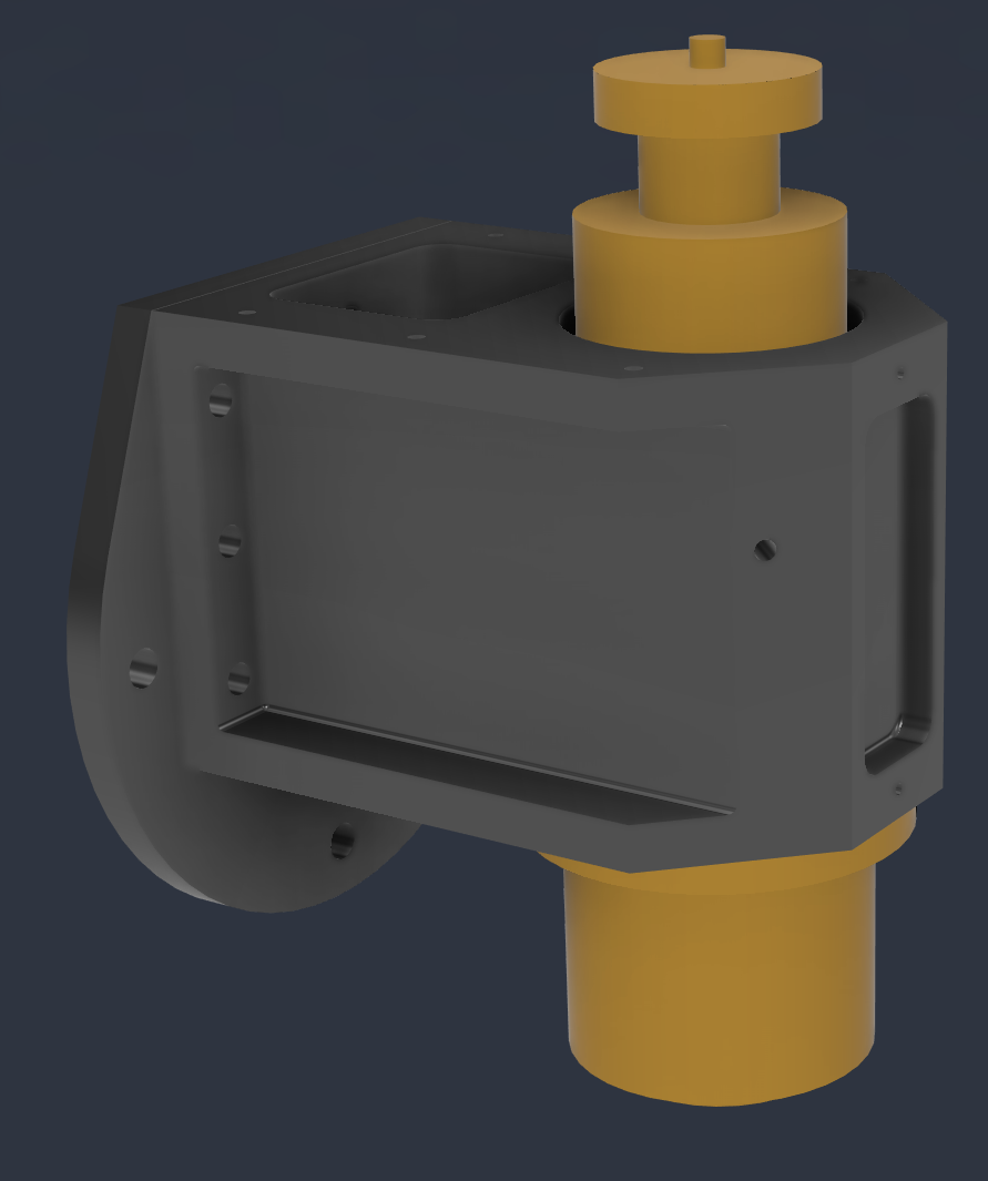
The reason why I did it in two parts is to be able to reuse the head itself when I move on to a larger machine frame some time in the future.
As the 120 mm hole in the head the for liquid cooled spindle needed to be made with very high precision I opted to have the parts made for me. This also enabled me to have the critical surfaces ground flat at the same time.
Here are the machined parts as they where delivered to me. Visible on the left side is also the pneumatic air cylinder I managed to find eBay.
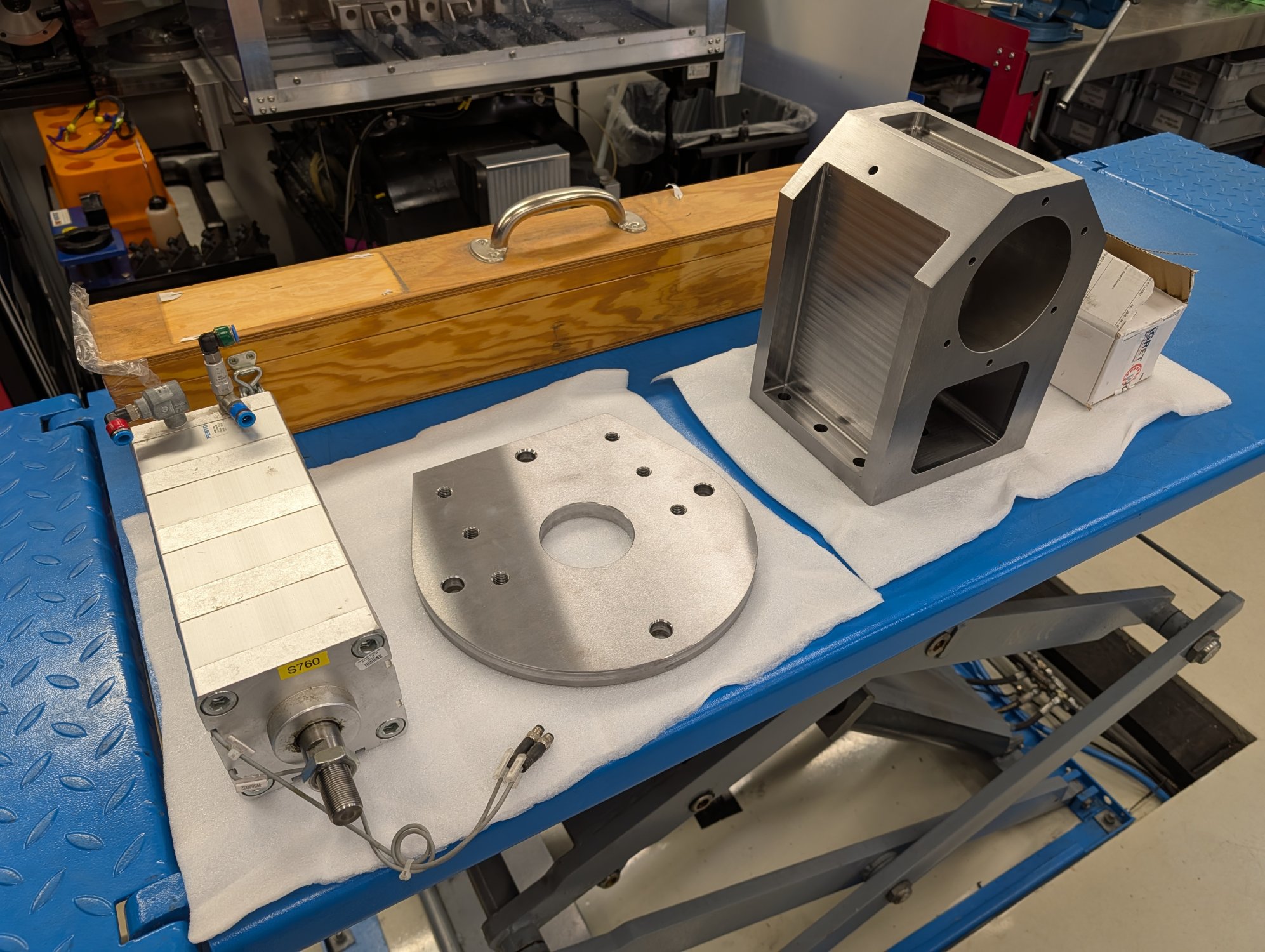
I try to avoid hydraulics as much as possible and so I was very happy to find a used stacked four stage 100 mm Festo pneumatic air cylinder for a very good price. It should provide enough force to release the drawbar in the new spindle at 8 bar of air pressure.
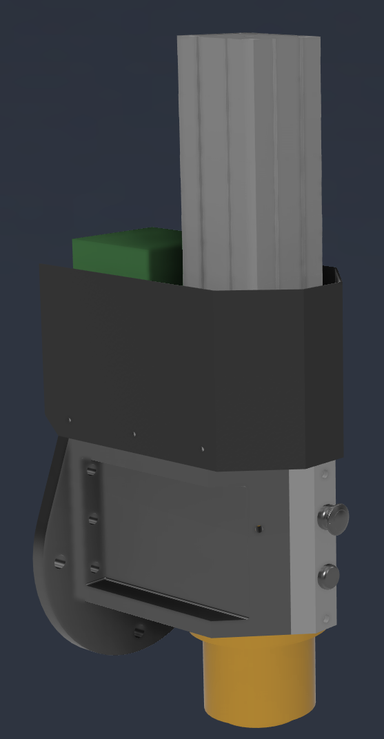
Here is how I have planned the milling head to looks with everything installed (with and without the top cover).
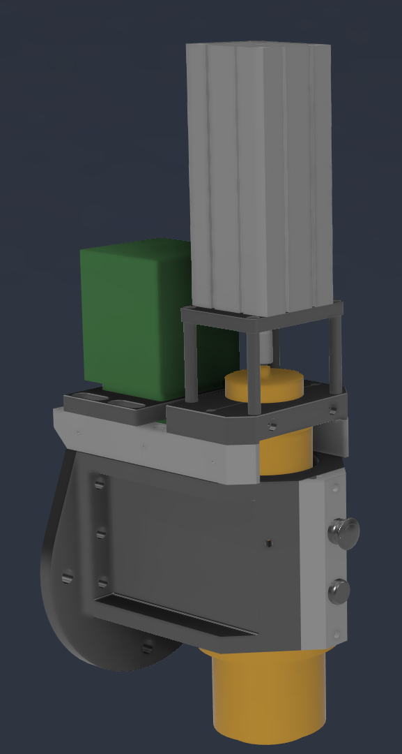
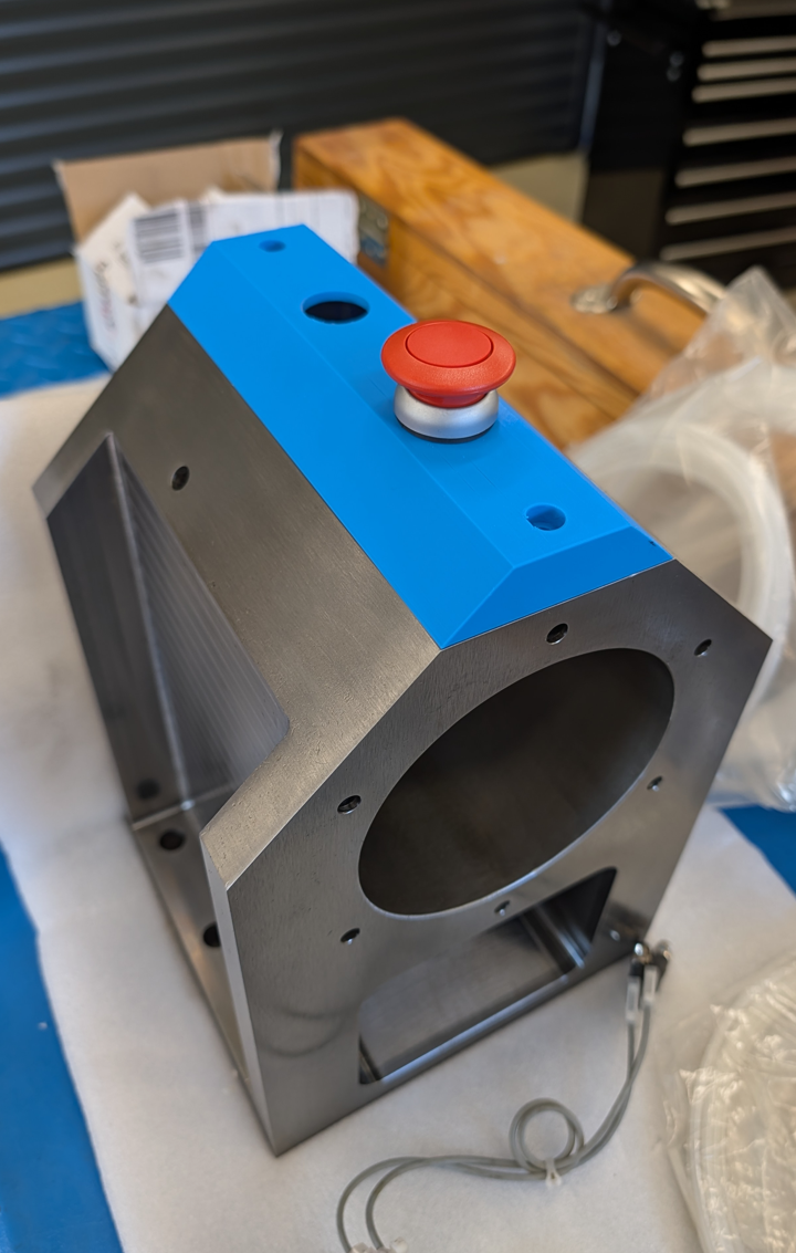
I 3D printed a test piece of the front button panel just to test the fitment and I think it came out okay.
I've created 19 different CAM programs to make all the remaining parts from aluminum which kept me busy for a while.
In order to reduce the load on the spindle bearings I'm going attach the mount for the pneumatic air cylinder with springs so that the majority of the clamping force goes in the to the drawbar instead of the bearings. Hence the slightly more complicated setup compared to my old setup.
The reason why I did it in two parts is to be able to reuse the head itself when I move on to a larger machine frame some time in the future.
As the 120 mm hole in the head the for liquid cooled spindle needed to be made with very high precision I opted to have the parts made for me. This also enabled me to have the critical surfaces ground flat at the same time.
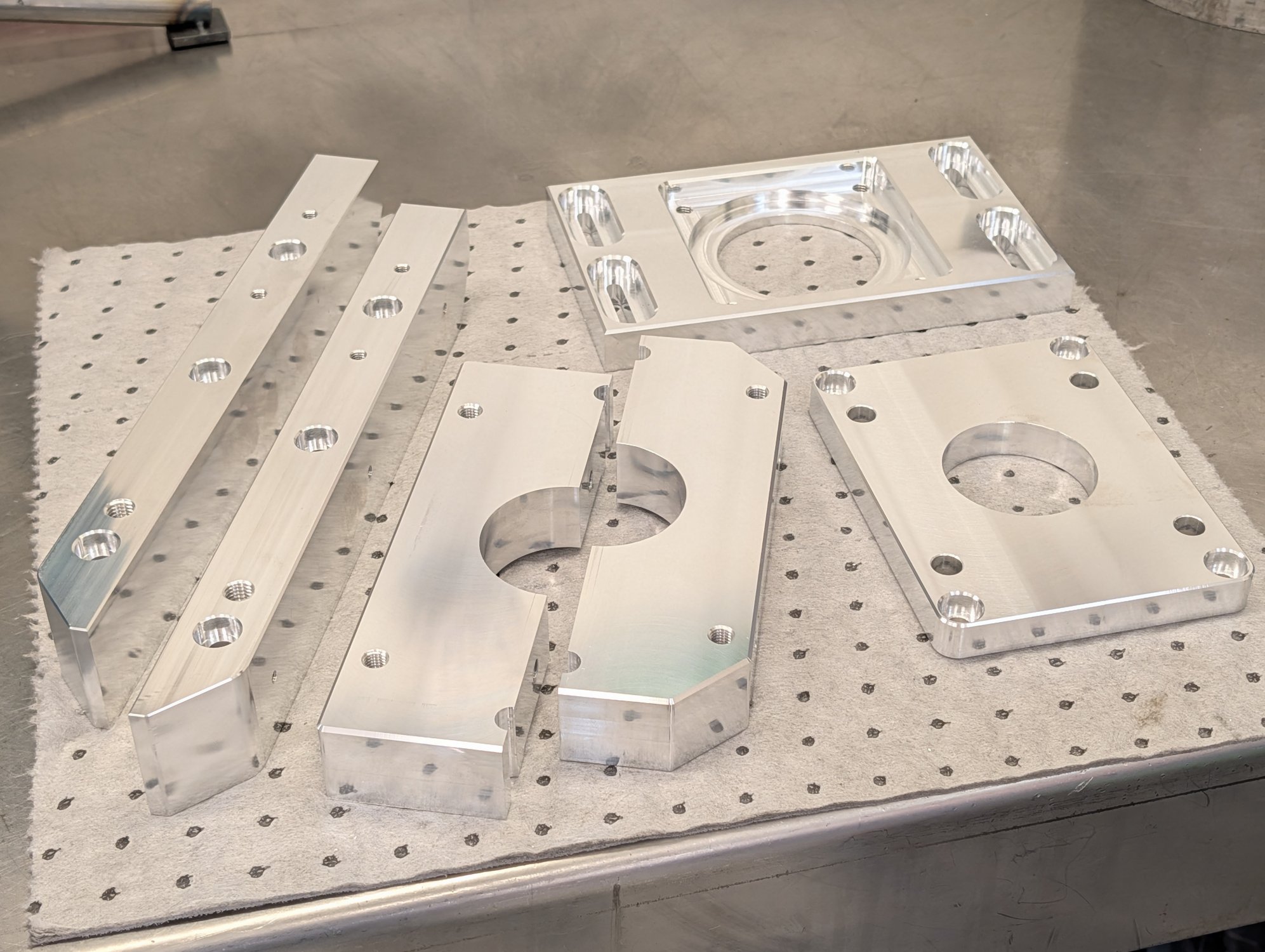
Here are the machined parts as they where delivered to me. Visible on the left side is also the pneumatic air cylinder I managed to find eBay.
I try to avoid hydraulics as much as possible and so I was very happy to find a used stacked four stage 100 mm Festo pneumatic air cylinder for a very good price. It should provide enough force to release the drawbar in the new spindle at 8 bar of air pressure.
Here is how I have planned the milling head to looks with everything installed (with and without the top cover).
I 3D printed a test piece of the front button panel just to test the fitment and I think it came out okay.
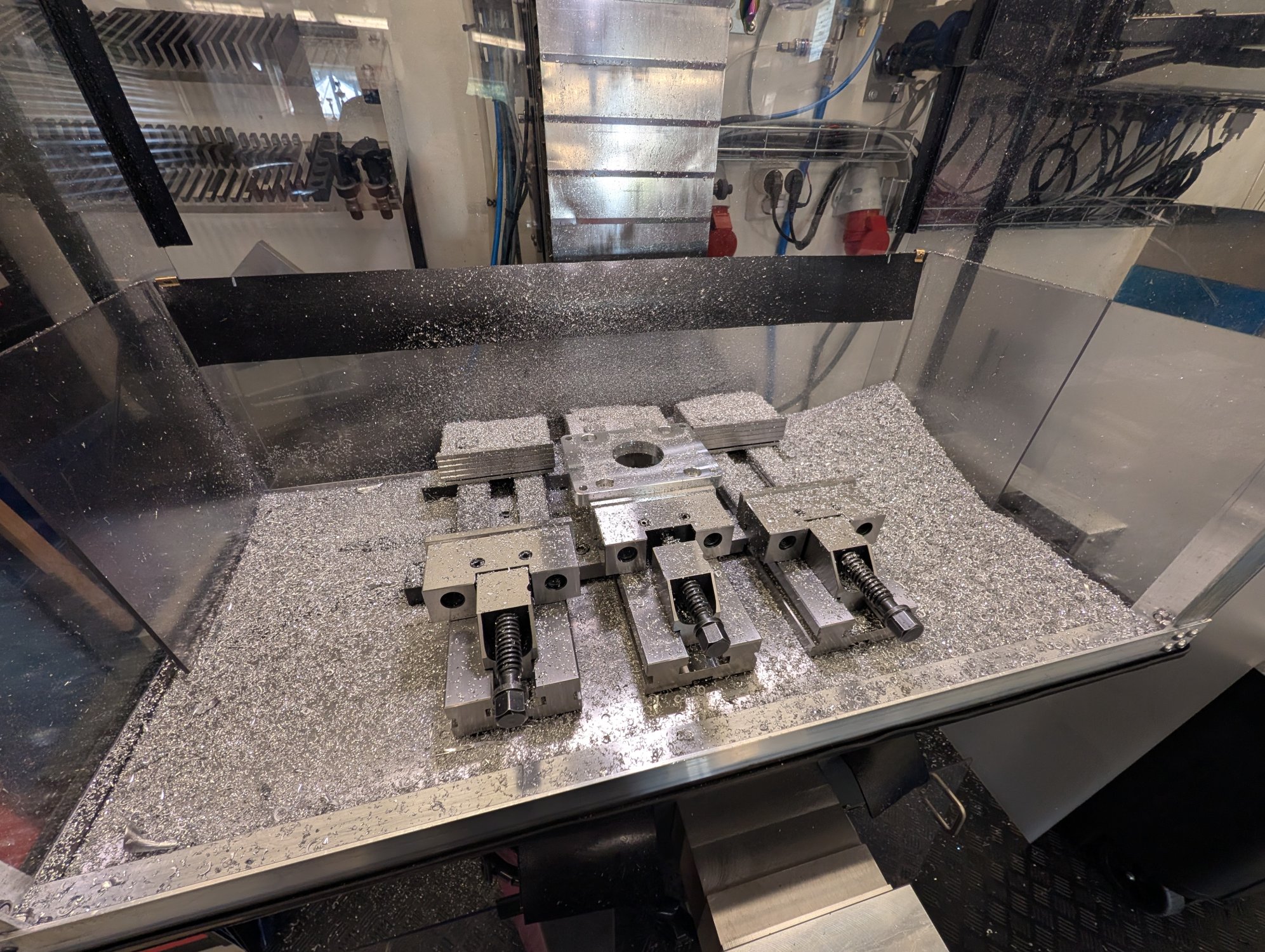
I've created 19 different CAM programs to make all the remaining parts from aluminum which kept me busy for a while.
In order to reduce the load on the spindle bearings I'm going attach the mount for the pneumatic air cylinder with springs so that the majority of the clamping force goes in the to the drawbar instead of the bearings. Hence the slightly more complicated setup compared to my old setup.
Attachments:
Last edit: 18 Sep 2026 19:01 by Unlogic.
Please Log in or Create an account to join the conversation.
- Unlogic
- Offline
- Elite Member
-
Less
More
- Posts: 251
- Thank you received: 123
18 Sep 2026 19:06 #349722
by Unlogic
Replied by Unlogic on topic Optimum Optimill MH50V CNC conversion
I have milled all of the parts now so it's time to start the assembly.
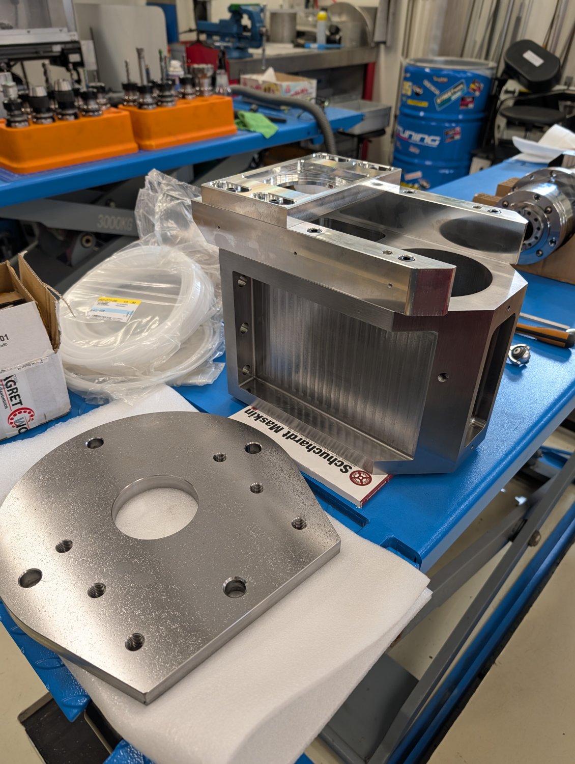
Here is a quick test fitment of some of the parts that will go on the new head.
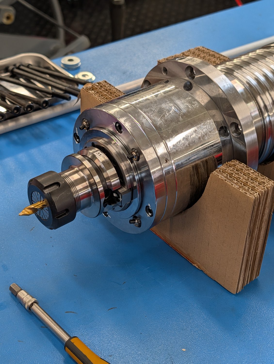
Here is a temporary setup to test if the stacked pneumatic cylinder was strong enough to release the drawbar.
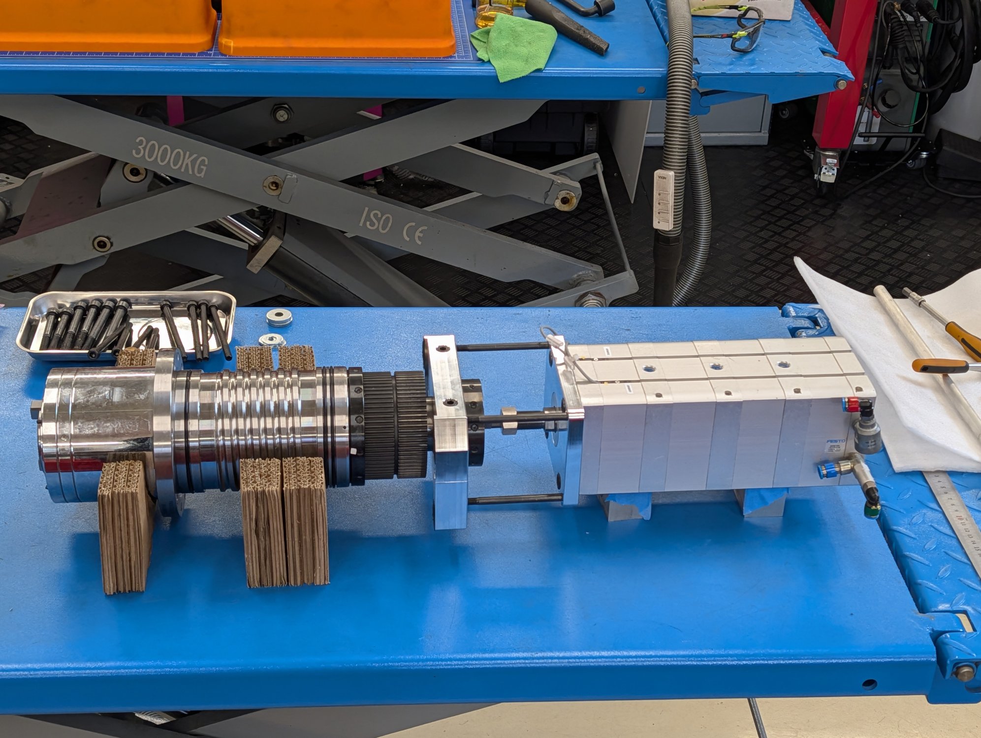
The test was a success and confirmed that the pneumatic cylinder could release the drawbar without any issues at 8 bar of air pressure.
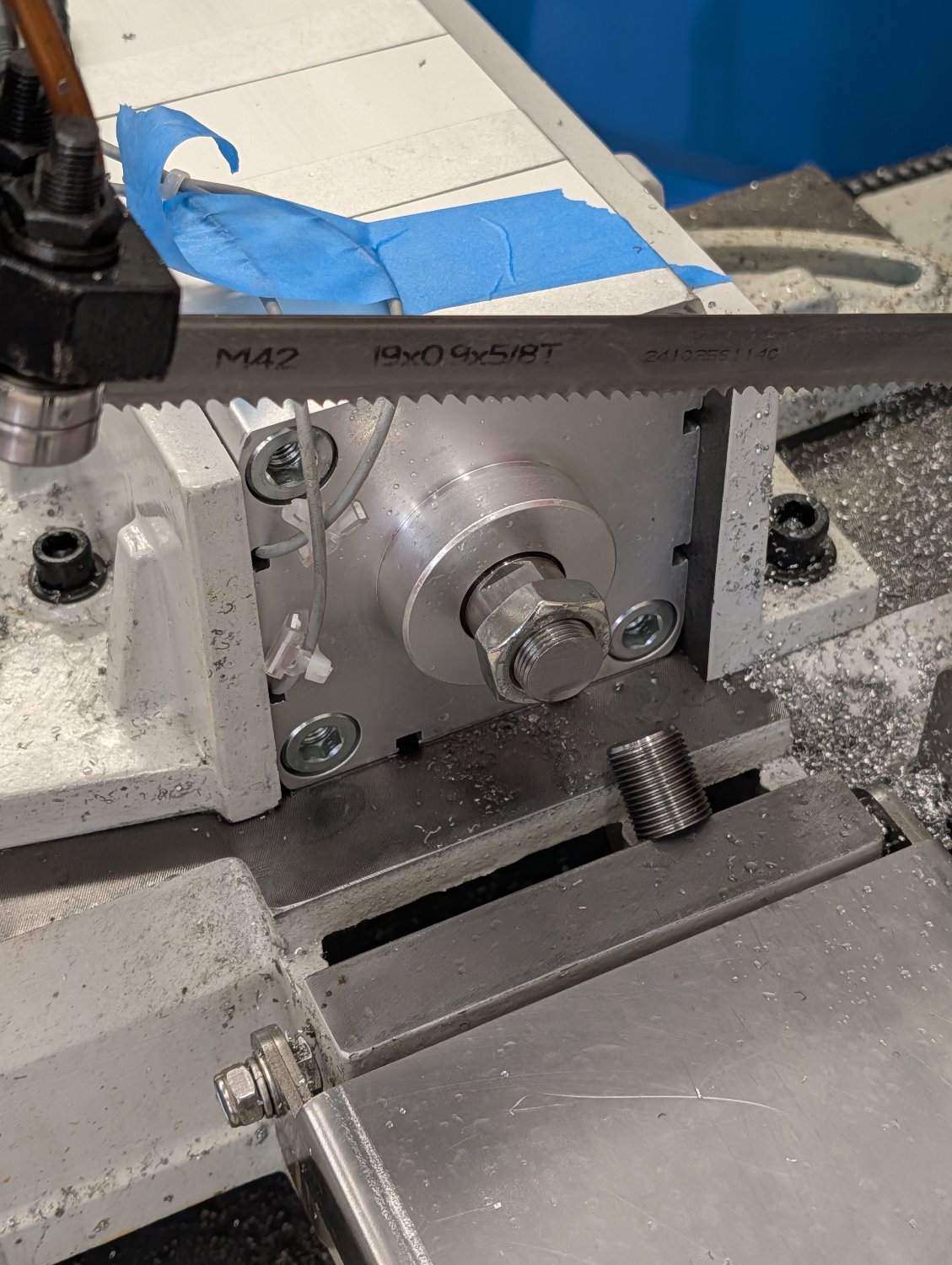
Once I had confirmed that the cylinder was working as intended I promptly put it in the bandsaw and shortened it a bit
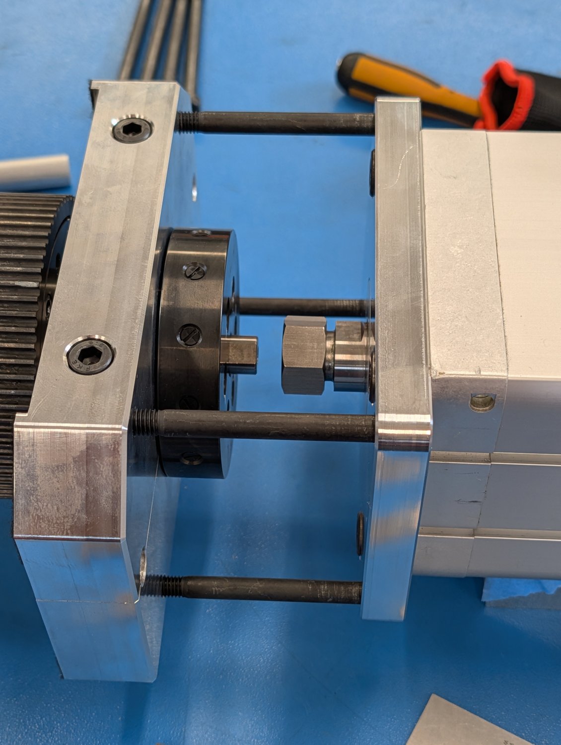
The next step is to make some aluminum sleeves for the four long bolts that hold the pneumatic cylinder to the lower fixture.
Here is a quick test fitment of some of the parts that will go on the new head.
Here is a temporary setup to test if the stacked pneumatic cylinder was strong enough to release the drawbar.
The test was a success and confirmed that the pneumatic cylinder could release the drawbar without any issues at 8 bar of air pressure.
Once I had confirmed that the cylinder was working as intended I promptly put it in the bandsaw and shortened it a bit
The next step is to make some aluminum sleeves for the four long bolts that hold the pneumatic cylinder to the lower fixture.
Attachments:
Please Log in or Create an account to join the conversation.
- Unlogic
- Offline
- Elite Member
-
Less
More
- Posts: 251
- Thank you received: 123
18 Sep 2026 19:08 #349723
by Unlogic
Replied by Unlogic on topic Optimum Optimill MH50V CNC conversion
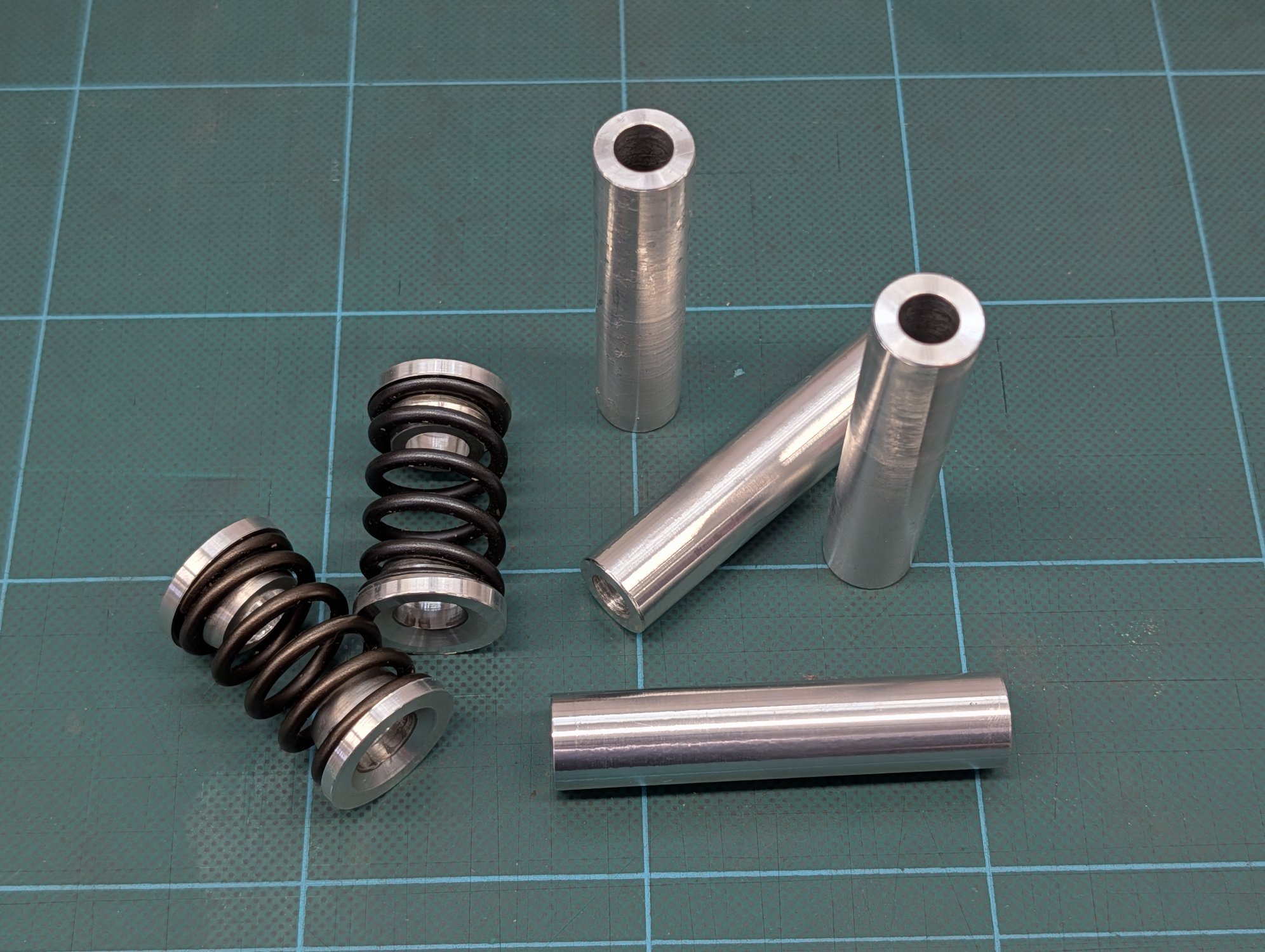
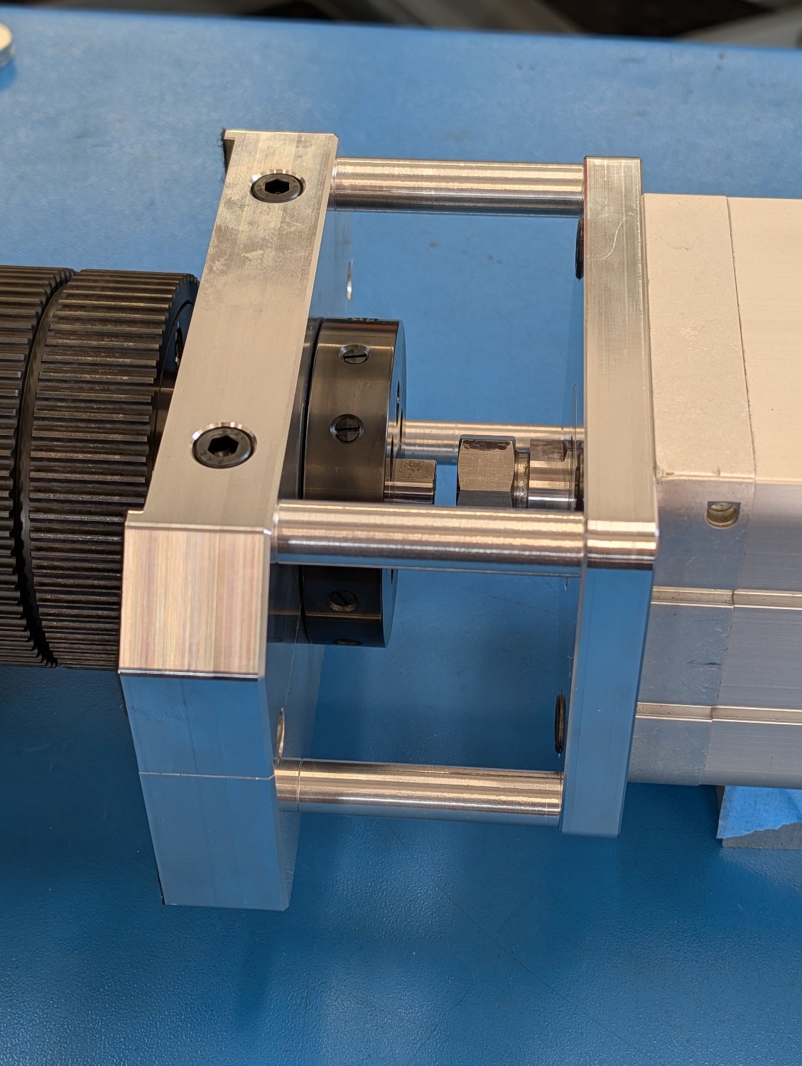
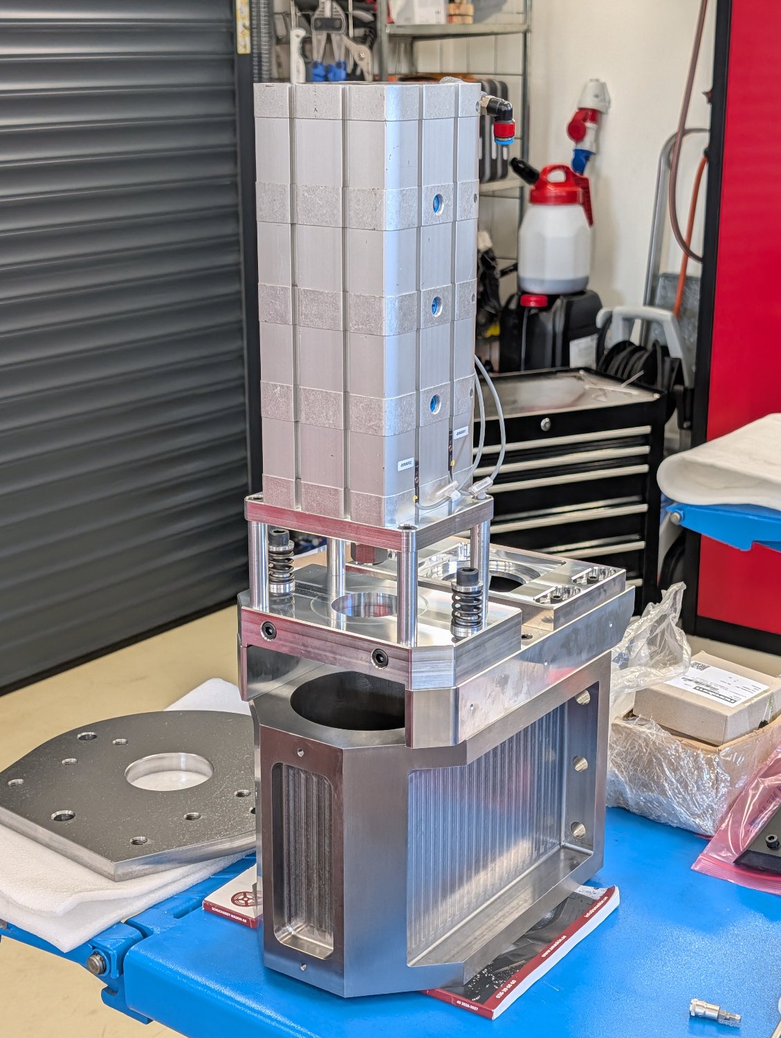
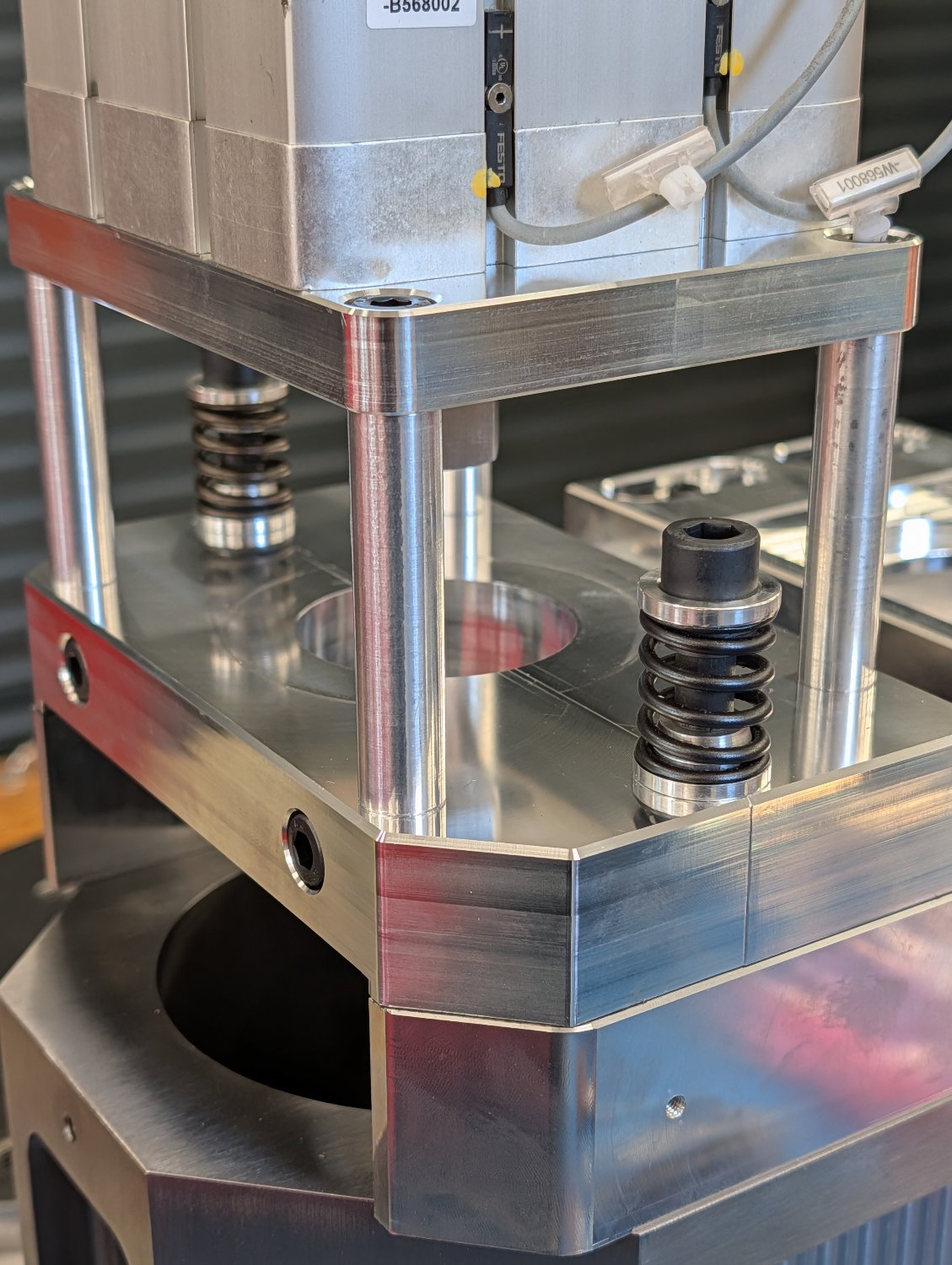
Here are the finished sleeves and the springs that hold down the pneumatic cylinder when it's idle. Used a set of old valve springs and retainers that were turned down a bit.
Attachments:
Please Log in or Create an account to join the conversation.
- Unlogic
- Offline
- Elite Member
-
Less
More
- Posts: 251
- Thank you received: 123
18 Sep 2026 19:14 #349724
by Unlogic
Replied by Unlogic on topic Optimum Optimill MH50V CNC conversion
With all the new parts done I began taking the machine apart starting with the head.
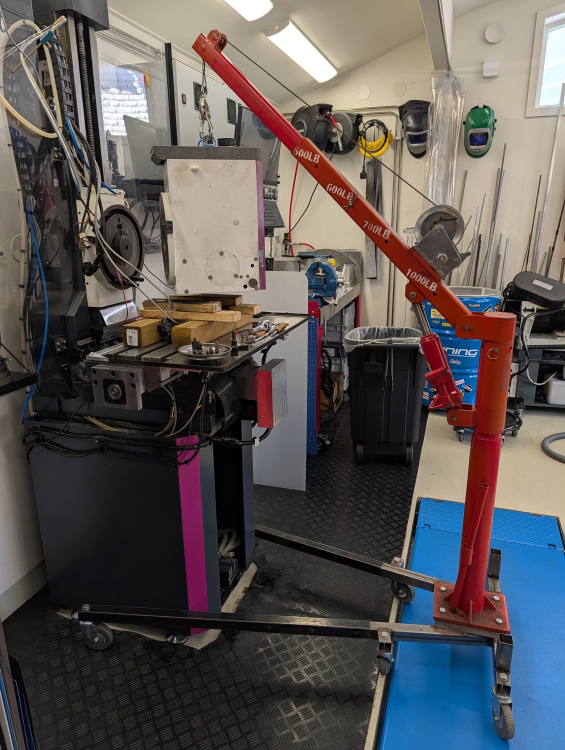
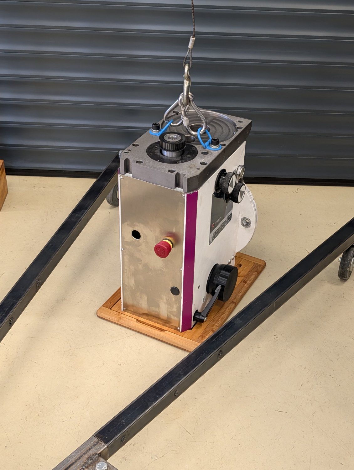
After that I did a test fit of the adapter plate for the new head which thankfully was a very tight fit.
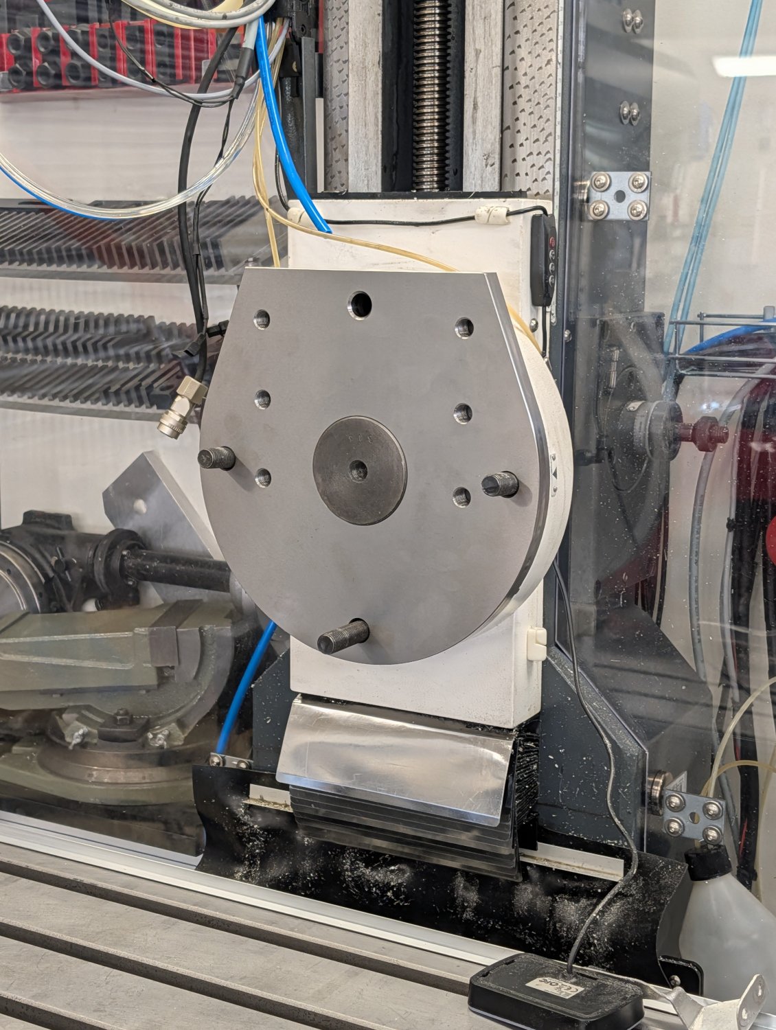
With the fitment confirmed I proceeded with removing the z-axis carriage from the machine.
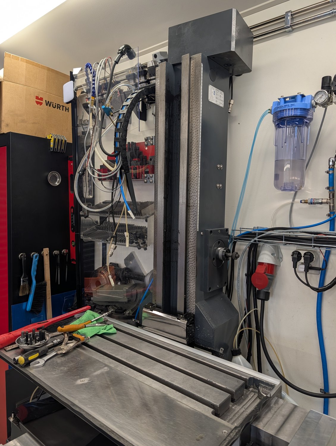
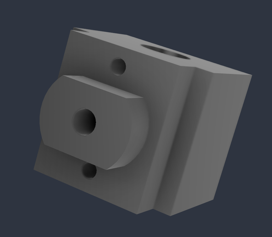
While I had everything apart I took the chance to make a CAD model of the mount for the z-axis ball nut so that I can make one for a ball screw later on.
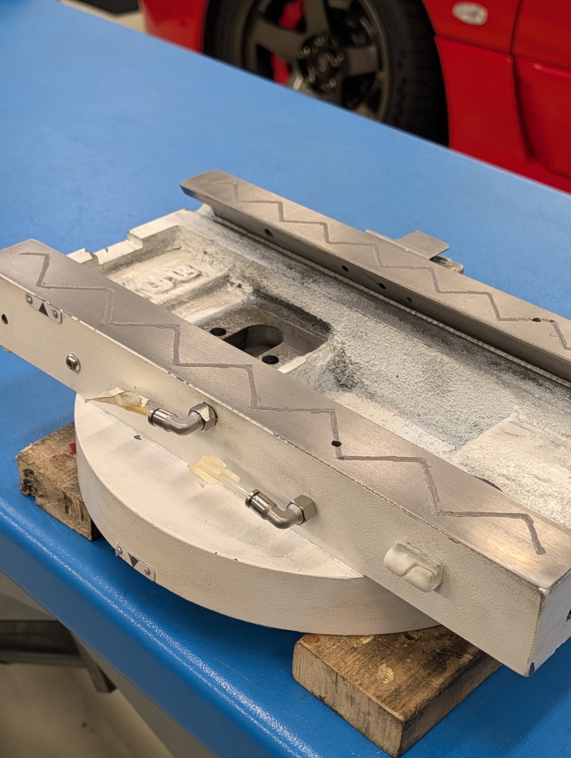
Next I proceeded with adding oil grooves to the z-axis carriage.
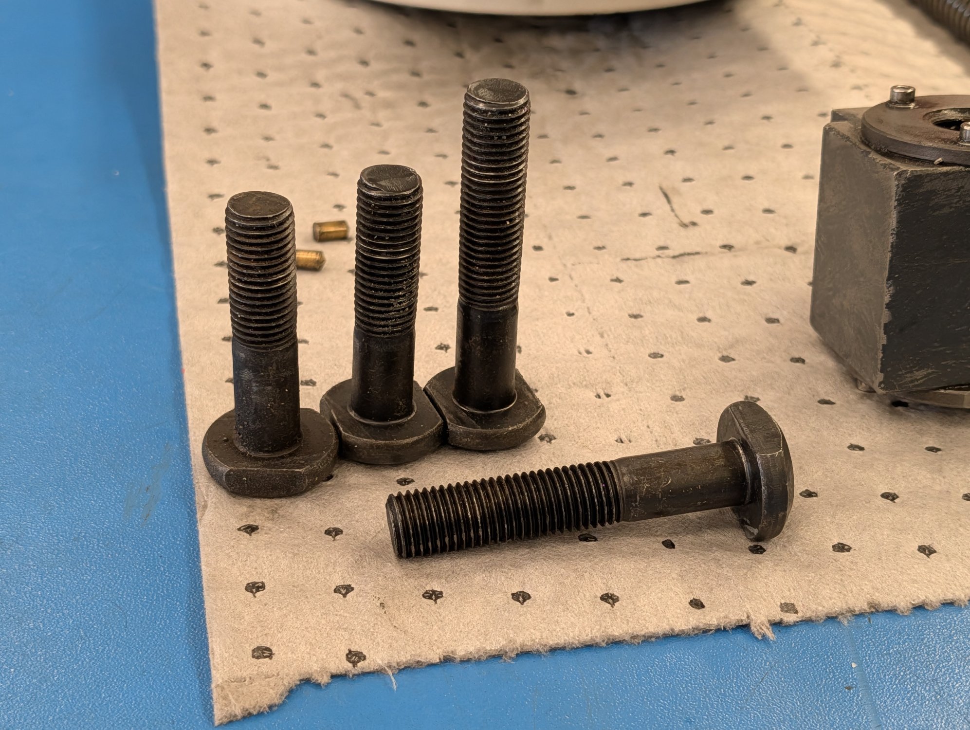
The stock head of this machine is attached using one center bolt and 3 outer bolts. The new head that I designed uses one more outer bolt for better rigidity. However the outer bolts have an oddly shaped head but luckily I manage to find a matching bolt.
After that I did a test fit of the adapter plate for the new head which thankfully was a very tight fit.
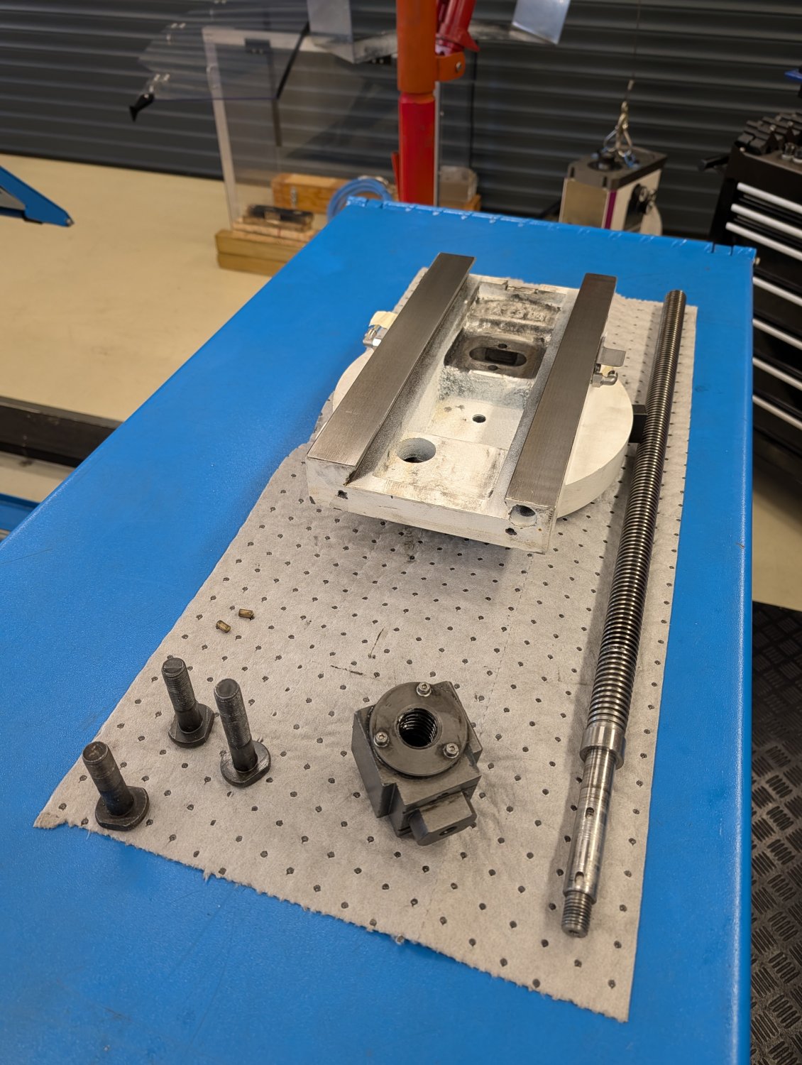
With the fitment confirmed I proceeded with removing the z-axis carriage from the machine.
While I had everything apart I took the chance to make a CAD model of the mount for the z-axis ball nut so that I can make one for a ball screw later on.
Next I proceeded with adding oil grooves to the z-axis carriage.
The stock head of this machine is attached using one center bolt and 3 outer bolts. The new head that I designed uses one more outer bolt for better rigidity. However the outer bolts have an oddly shaped head but luckily I manage to find a matching bolt.
Attachments:
Please Log in or Create an account to join the conversation.
- Unlogic
- Offline
- Elite Member
-
Less
More
- Posts: 251
- Thank you received: 123
18 Sep 2026 19:20 #349725
by Unlogic
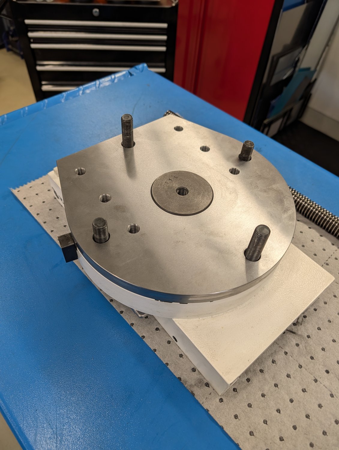
With the bolts sorted I proceeded with quick test fitment of the major parts.
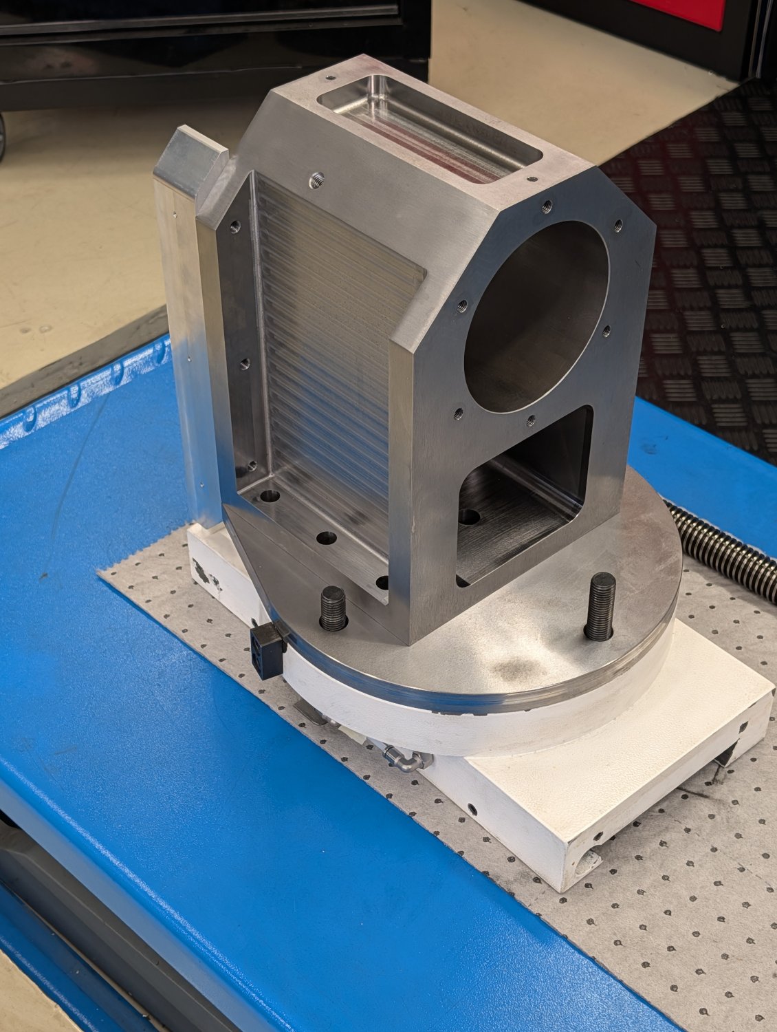
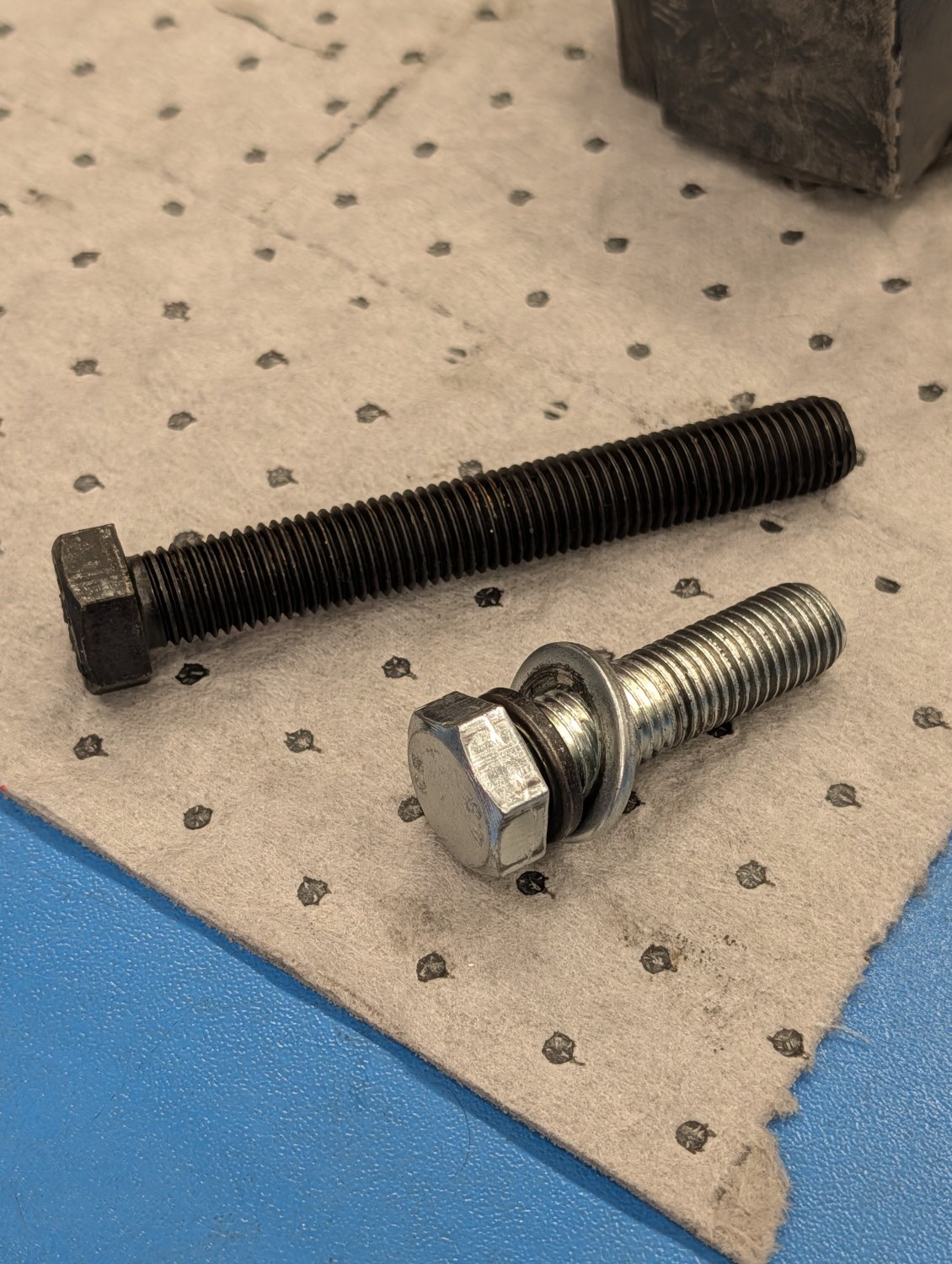
While I was doing this I noticed that the stock center bolt was only 4.8 grade which is very weak so I replaced it with a 12.9 grade bolt instead.
Before taking the machine apart I had taken the time to lookup which bearing type that is used for the z-axis lead screw on this machine as they have been making noises for quite some time.
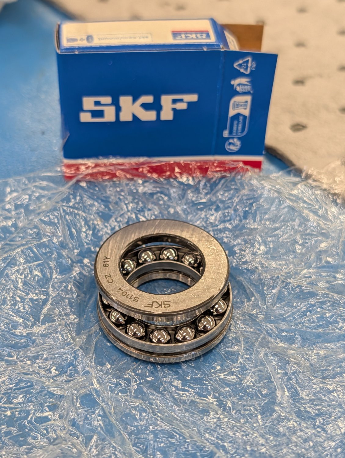
According to the manual for this machine the z-axis lead screw is supposed to use 51104 single direction thrust ball bearings so I ordered a set of those from SKF.
However when I removed the lead screw from the machine I was greeted by this, WS81104 roller bearings...
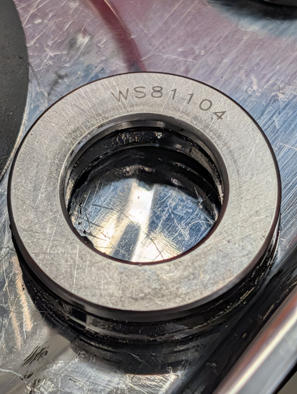
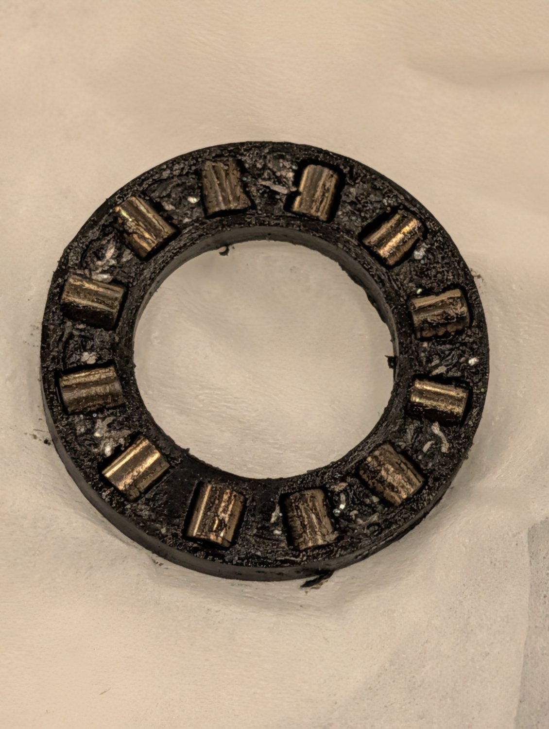
Roller bearings are much better at carrying this type of loads and I would have preferred to install a new set. But since all I had available was the 51104 single direction thrust ball bearings I installed them for now...
As you can see from the photo above the old roller bearings where full of metal chips which is not surprising given that they are of an open design.
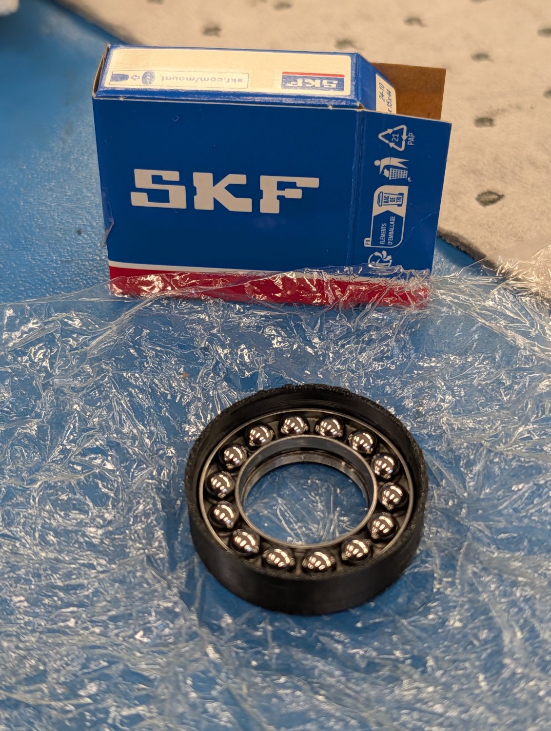
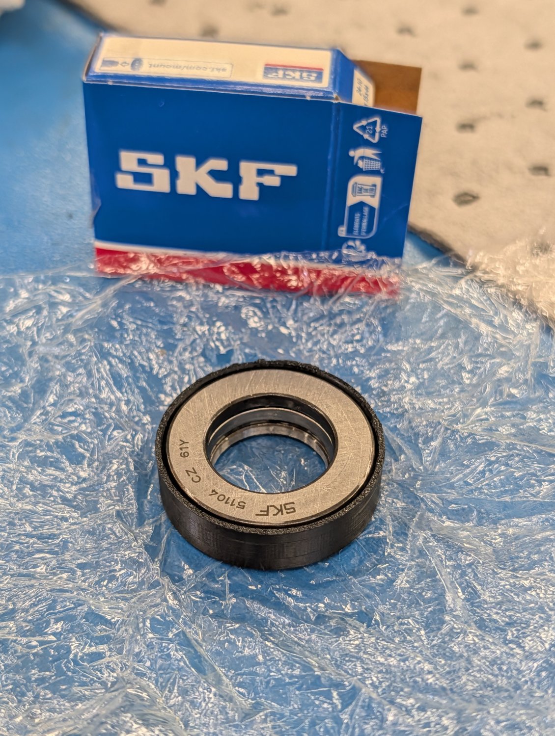
To try and avoid this issue with the new bearing I 3D printed a set of collars from ASA plastic for the new bearings.
Replied by Unlogic on topic Optimum Optimill MH50V CNC conversion
With the bolts sorted I proceeded with quick test fitment of the major parts.
While I was doing this I noticed that the stock center bolt was only 4.8 grade which is very weak so I replaced it with a 12.9 grade bolt instead.
Before taking the machine apart I had taken the time to lookup which bearing type that is used for the z-axis lead screw on this machine as they have been making noises for quite some time.
According to the manual for this machine the z-axis lead screw is supposed to use 51104 single direction thrust ball bearings so I ordered a set of those from SKF.
However when I removed the lead screw from the machine I was greeted by this, WS81104 roller bearings...
Roller bearings are much better at carrying this type of loads and I would have preferred to install a new set. But since all I had available was the 51104 single direction thrust ball bearings I installed them for now...
As you can see from the photo above the old roller bearings where full of metal chips which is not surprising given that they are of an open design.
To try and avoid this issue with the new bearing I 3D printed a set of collars from ASA plastic for the new bearings.
Attachments:
Please Log in or Create an account to join the conversation.
- Unlogic
- Offline
- Elite Member
-
Less
More
- Posts: 251
- Thank you received: 123
18 Sep 2026 19:27 #349726
by Unlogic
Replied by Unlogic on topic Optimum Optimill MH50V CNC conversion
After getting the bearings sorted I reinstalled the z-axis carriage and the lead screw along with the lines for the central lubrication so that I could adjust the gibs and do some measurements.
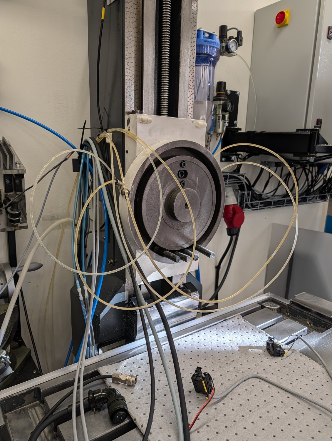
This machine has always had a bit of a head nod which I've had to compensate for by shimming the head. I was hoping that it was a defect with the old head but it turned out to come from the z-axis carriage so I'll have to use shims for the new head too.
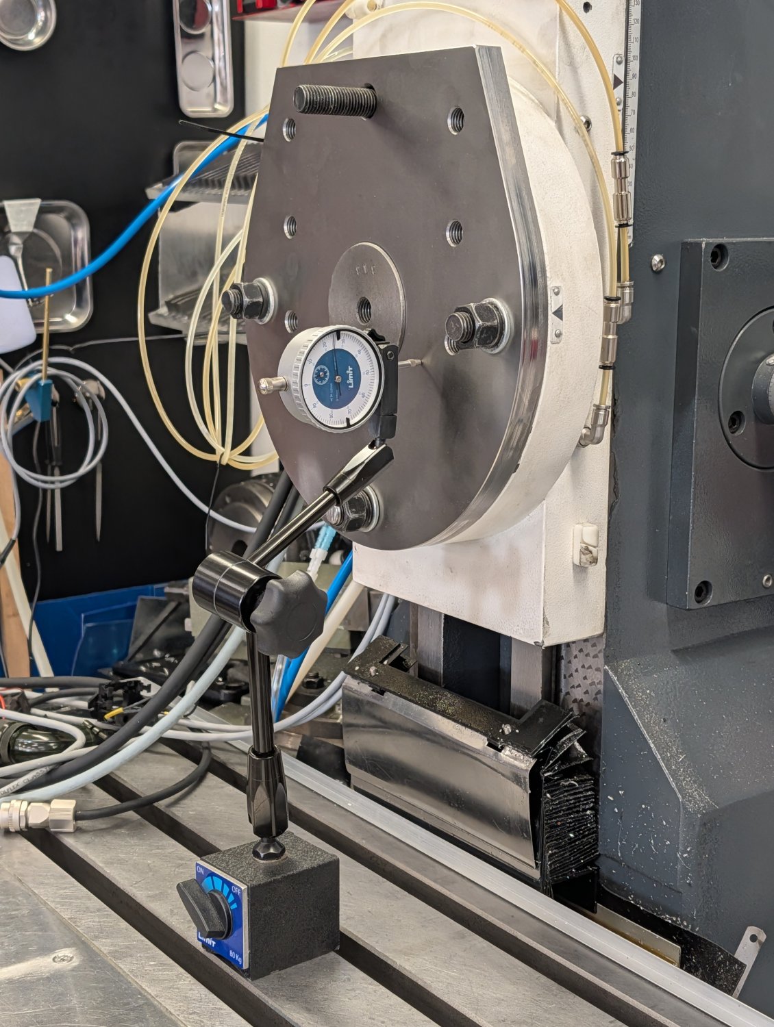
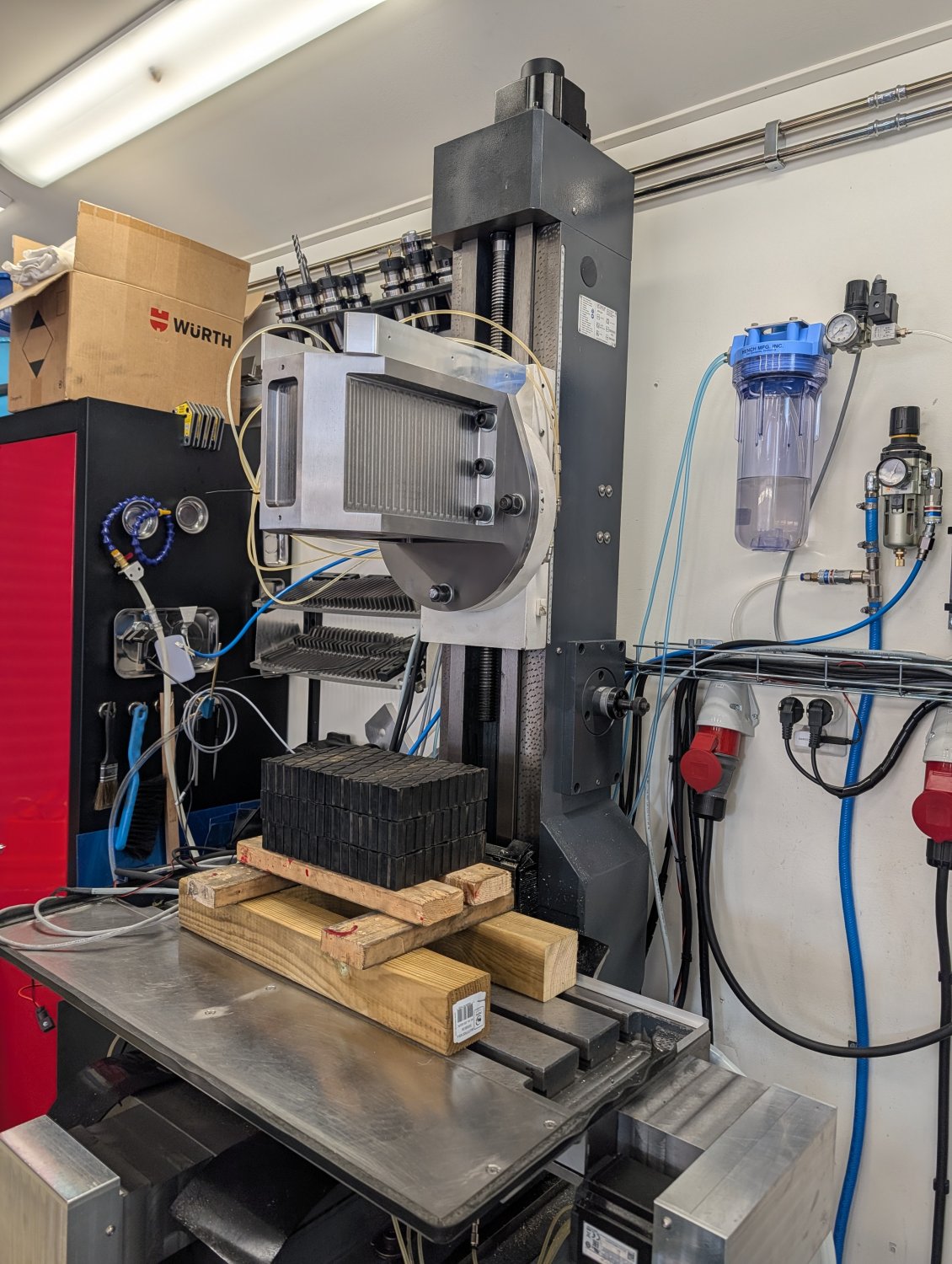
With the measurements taken I installed the new head.
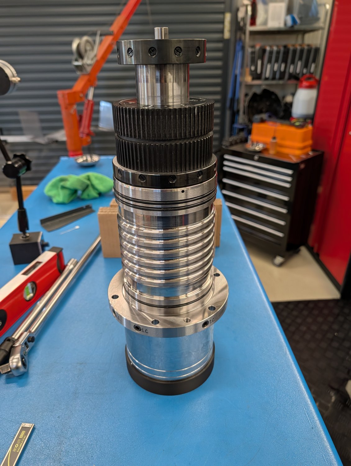
With the new spindle being rather heavy, fragile and quite expensive I 3D printed a small stand for it so that I could have it upright without putting any force on the bearings.
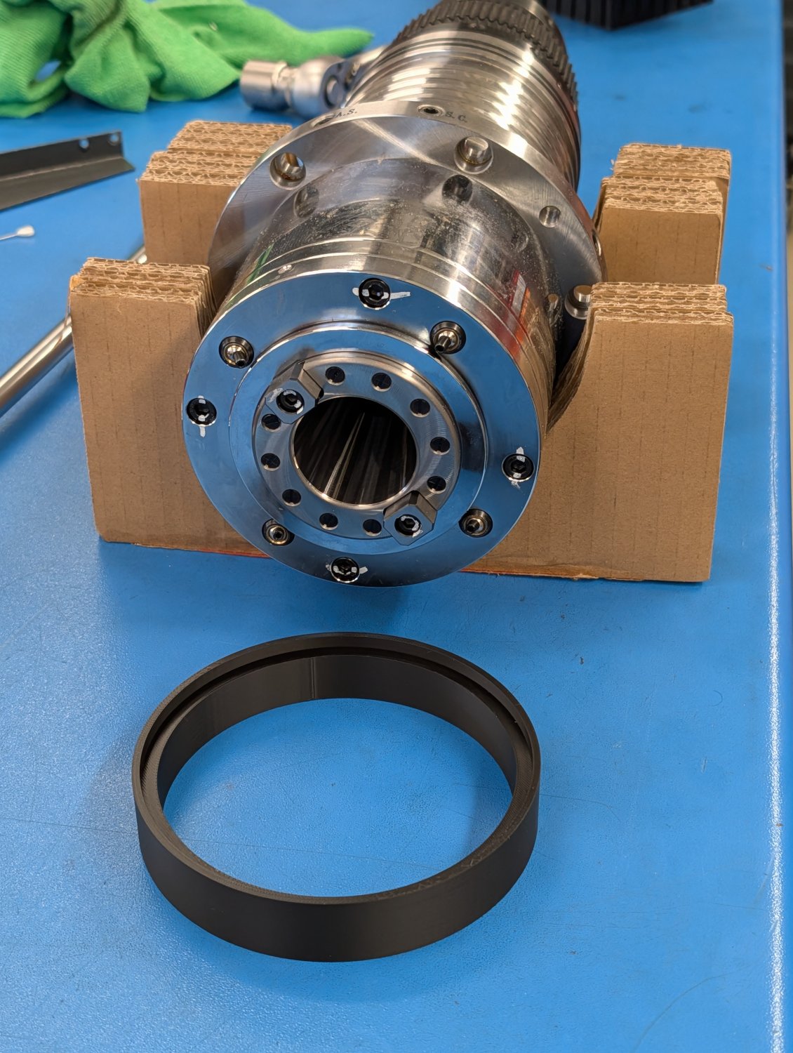
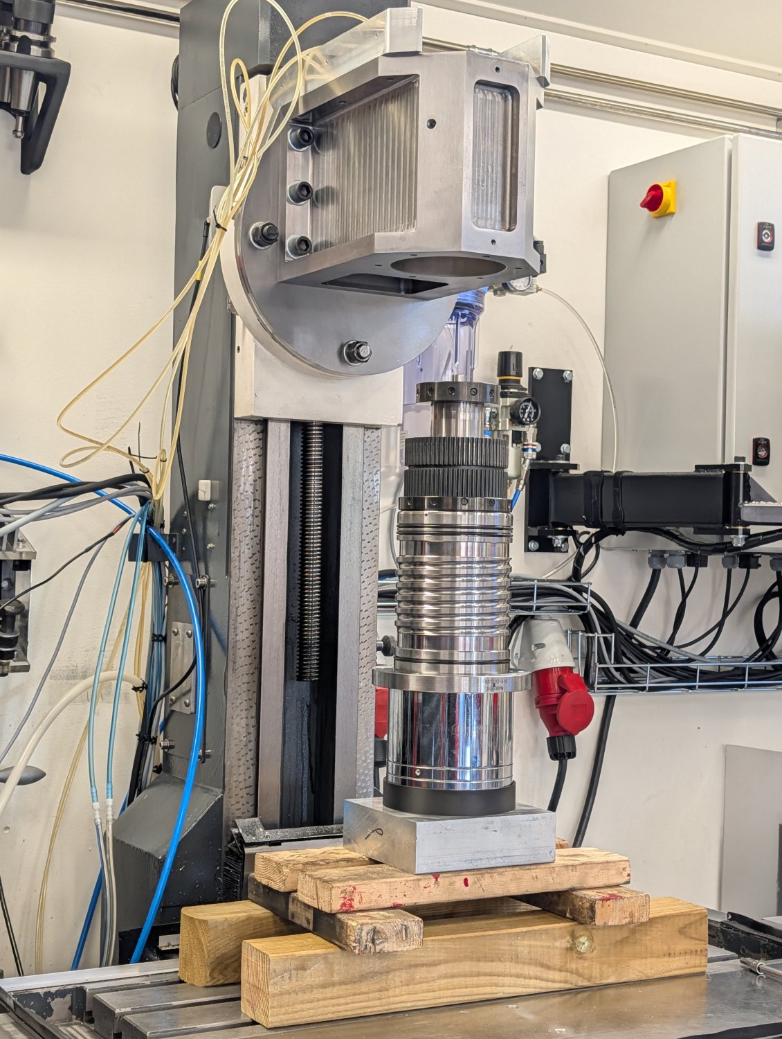
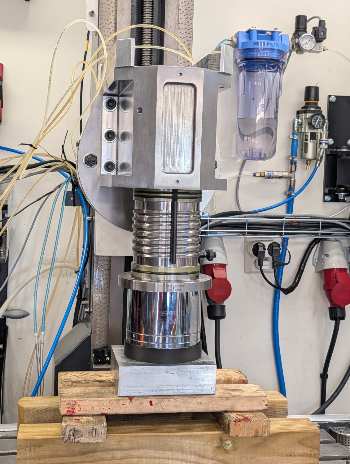
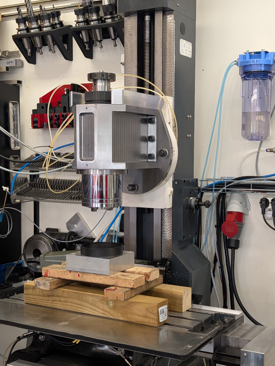
Installing the spindle was a bit nerve wrecking as the hole for it in the new head only has a clearance of one hundred of a millimeter.
So I took my time and slowly got it in place.
This machine has always had a bit of a head nod which I've had to compensate for by shimming the head. I was hoping that it was a defect with the old head but it turned out to come from the z-axis carriage so I'll have to use shims for the new head too.
With the measurements taken I installed the new head.
With the new spindle being rather heavy, fragile and quite expensive I 3D printed a small stand for it so that I could have it upright without putting any force on the bearings.
Installing the spindle was a bit nerve wrecking as the hole for it in the new head only has a clearance of one hundred of a millimeter.
So I took my time and slowly got it in place.
Attachments:
The following user(s) said Thank You: tommylight
Please Log in or Create an account to join the conversation.
- Unlogic
- Offline
- Elite Member
-
Less
More
- Posts: 251
- Thank you received: 123
18 Sep 2026 19:30 #349727
by Unlogic
Replied by Unlogic on topic Optimum Optimill MH50V CNC conversion
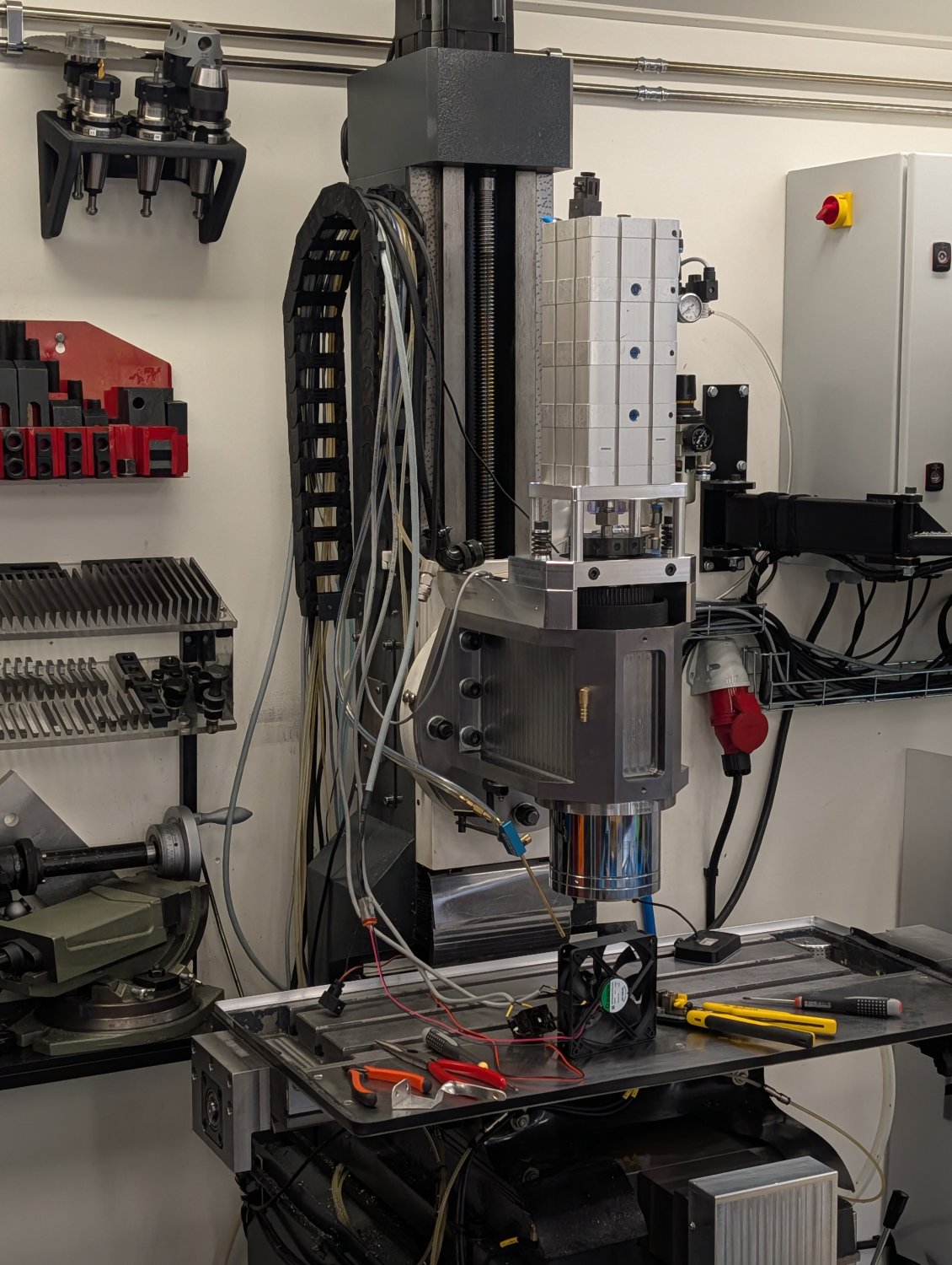
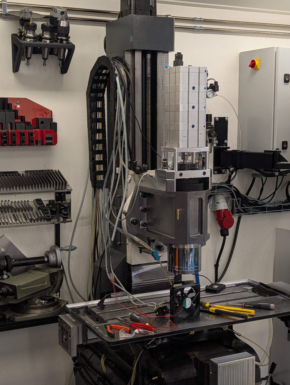
With the spindle installed I was keen on testing the pneumatic cylinder for the drawbar to make sure the whole assembly worked as planned.
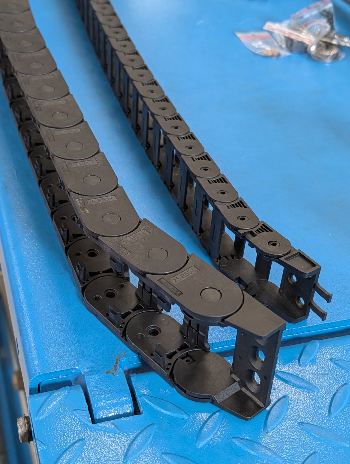
The next thing to tackle was the drag chain. The old one was completely full long ago and did not have space for the spindle cooling lines or the flood cooling line so I bought a larger one made from nylon which seems very sturdy.
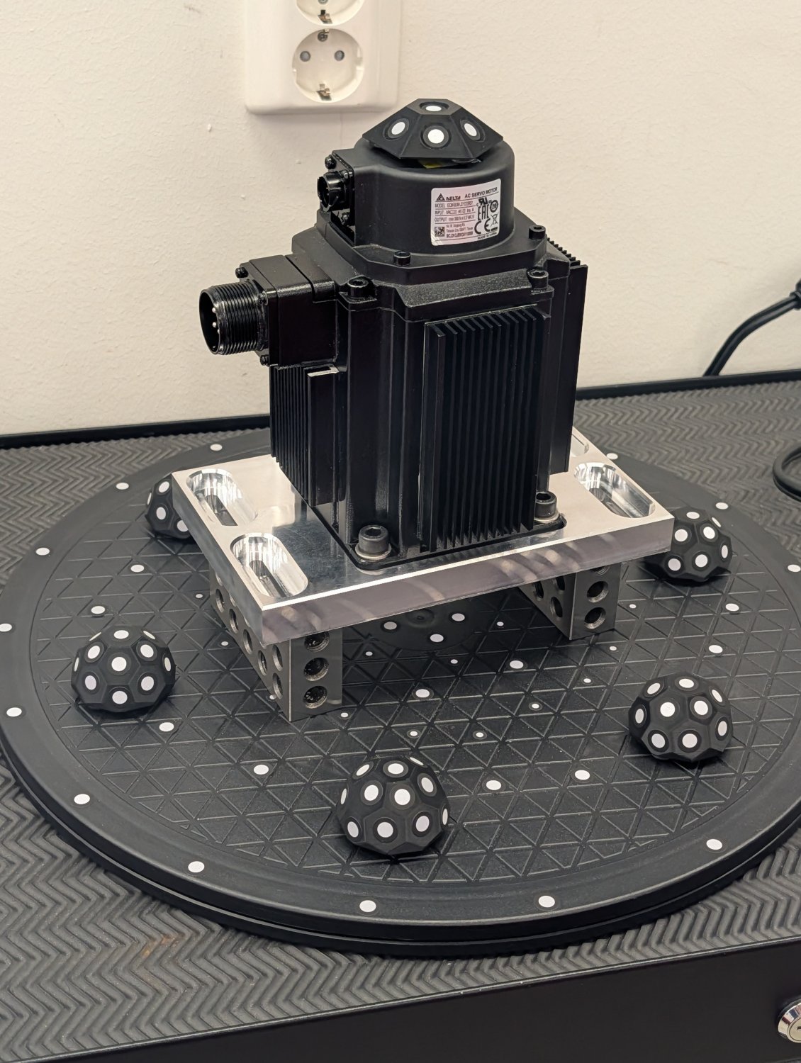
The Delta 2kw 6000 rpm servo I'm using for the spindle has been running at only for 3500 rpm previously due to my old spindle. Since it's going to be running at it's maximum rated speed of 6000 rpm now I decided to improve the cooling of it a bit to make sure it doesn't overheat.
I started by 3D scanning the servo and it's mounting plate.
And around that model I designed the fan shroud.
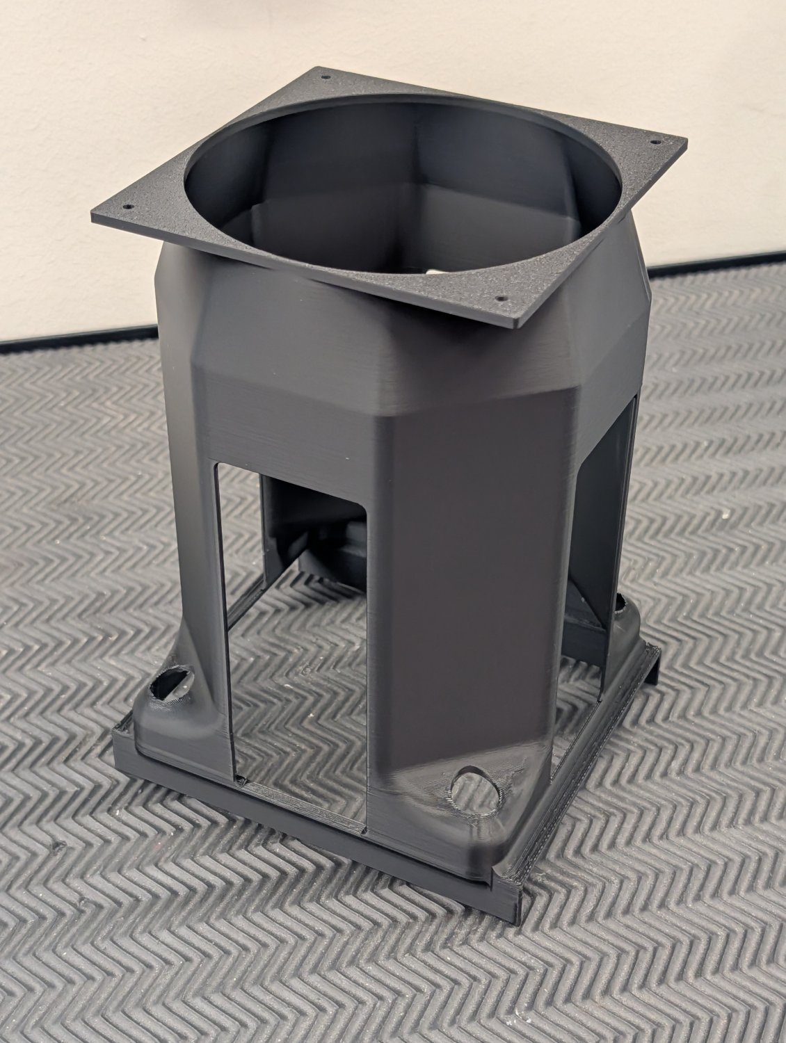

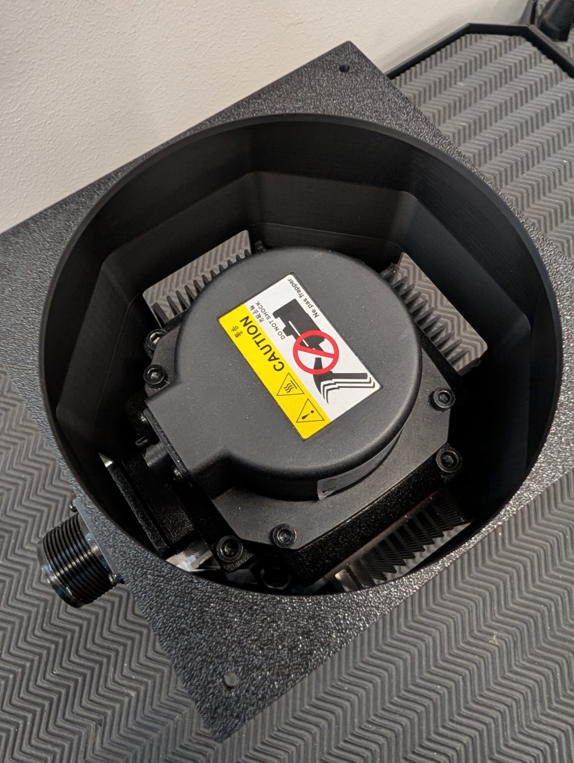
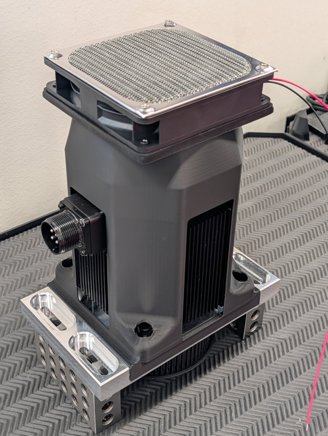
The next thing to tackle was the drag chain. The old one was completely full long ago and did not have space for the spindle cooling lines or the flood cooling line so I bought a larger one made from nylon which seems very sturdy.
The Delta 2kw 6000 rpm servo I'm using for the spindle has been running at only for 3500 rpm previously due to my old spindle. Since it's going to be running at it's maximum rated speed of 6000 rpm now I decided to improve the cooling of it a bit to make sure it doesn't overheat.
I started by 3D scanning the servo and it's mounting plate.
And around that model I designed the fan shroud.
Attachments:
The following user(s) said Thank You: tommylight
Please Log in or Create an account to join the conversation.
- Unlogic
- Offline
- Elite Member
-
Less
More
- Posts: 251
- Thank you received: 123
18 Sep 2026 19:32 - 18 Sep 2026 19:33 #349728
by Unlogic
Replied by Unlogic on topic Optimum Optimill MH50V CNC conversion
However when it was time to install the servo on the new head I realized that I had forgotten about the connector for the encoder so I had to open up the shroud a bit more on one side.
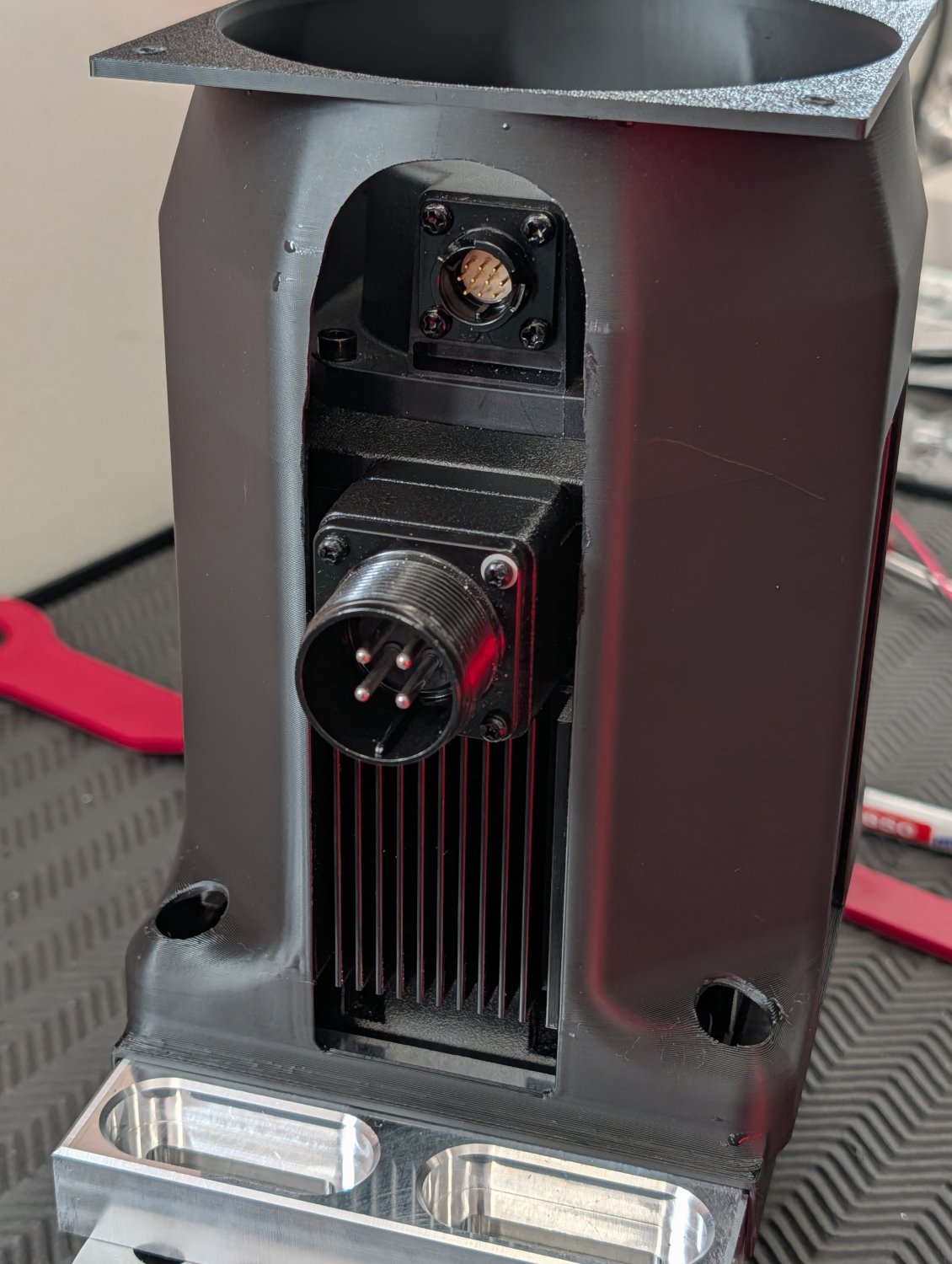
With that fixed I installed the servo on the machine.
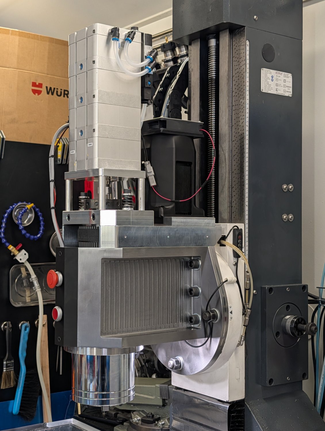
With the major components in place it was time for a first quick test
Next up is the liquid cooling for the spindle and then running in the new spindle bearings.
With that fixed I installed the servo on the machine.
With the major components in place it was time for a first quick test
Next up is the liquid cooling for the spindle and then running in the new spindle bearings.
Attachments:
Last edit: 18 Sep 2026 19:33 by Unlogic.
The following user(s) said Thank You: tommylight
Please Log in or Create an account to join the conversation.
- tommylight
-

- Away
- Moderator
-

Less
More
- Posts: 21898
- Thank you received: 7465
18 Sep 2026 19:33 #349729
by tommylight
Replied by tommylight on topic Optimum Optimill MH50V CNC conversion
AWESOME !!!
Please Log in or Create an account to join the conversation.
- Unlogic
- Offline
- Elite Member
-
Less
More
- Posts: 251
- Thank you received: 123
18 Sep 2026 19:35 #349730
by Unlogic
Replied by Unlogic on topic Optimum Optimill MH50V CNC conversion
Thanks Tommy, it's been a long journey getting here.
Hopefully the new spindle will allow me to mill parts significantly faster than before.
Hopefully the new spindle will allow me to mill parts significantly faster than before.
Please Log in or Create an account to join the conversation.
Moderators: piasdom
Time to create page: 4.500 seconds