- Hardware & Machines
- Computers and Hardware
- LinuxCNC-RIO - RealtimeIO for LinuxCNC based on FPGA (ICE40 / ECP5)
LinuxCNC-RIO - RealtimeIO for LinuxCNC based on FPGA (ICE40 / ECP5)
- mBender
- Offline
- Premium Member
-

Less
More
- Posts: 133
- Thank you received: 15
04 Nov 2024 14:04 #313755
by mBender
Replied by mBender on topic LinuxCNC-RIO - RealtimeIO for LinuxCNC based on FPGA (ICE40 / ECP5)
Attachments:
Please Log in or Create an account to join the conversation.
- digiex_chris
- Offline
- Senior Member
-

Less
More
- Posts: 40
- Thank you received: 11
04 Nov 2024 18:49 #313770
by digiex_chris
What error messages? I had to tune FERROR and MIN_FERROR a bit for my setup to solve some following errors.
Replied by digiex_chris on topic LinuxCNC-RIO - RealtimeIO for LinuxCNC based on FPGA (ICE40 / ECP5)
Just a thought, try setting the feed rate very very low, and maybe with a low scale factor. I noticed on my board (based on rio-iceshield but with slightly different parts and design), after about 2khz, the output signal no longer falls near zero and I get a strange offset sawtooth on the oscilloscope. Around 1.6khz I get nearly a sine wave, but with a flat bottom. Under 1khz I get a nice square wave. So I think I have some capacitance issues or the line driver isn't fast enough. Still digging into it. the ULN2803A I used looks like it's fast enough based on the datasheet but who knows!Awesome. I will test it with my oscilloscope. I wonder if I need something like a pull down resistor after/before the level shifter.
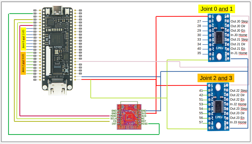
I noticed that the one of my outputs is not always switching. It's tied to the "machine on" but when I toggle the machine on an off, sometimes it's not reacting. I also get some error messages in the Terminal.
This is my current wiring.
What error messages? I had to tune FERROR and MIN_FERROR a bit for my setup to solve some following errors.
Please Log in or Create an account to join the conversation.
- digiex_chris
- Offline
- Senior Member
-

Less
More
- Posts: 40
- Thank you received: 11
04 Nov 2024 19:32 #313774
by digiex_chris
Quick question about the iceshield config:
Should the pi be emitting 18mHz, rather than 5mhz via pin 7 instead, since the oscillator is configured as 18mhz on pin 35 on the up5k? I wonder if this is the source of my following error at higher speeds?
Replied by digiex_chris on topic LinuxCNC-RIO - RealtimeIO for LinuxCNC based on FPGA (ICE40 / ECP5)
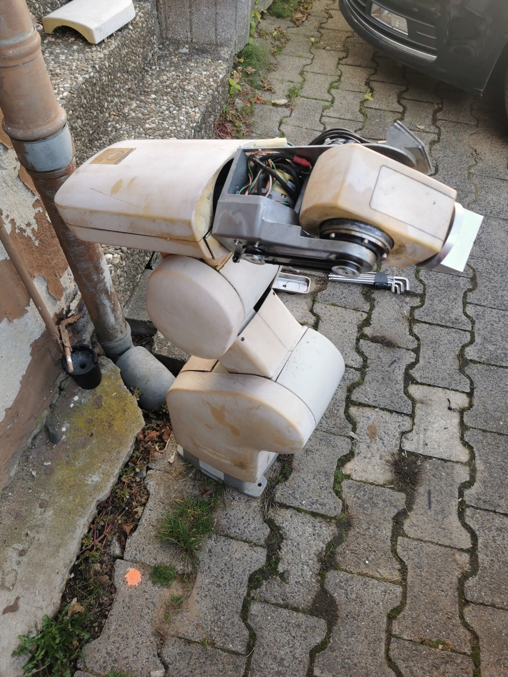
I approve of this excuse!if i have overlooked any open questions, please ask again, i was a bit busy at the weekend and lost the thread
here is my excuse:mitsubishi rv-e2
without controller and one harmonic drive is broken
Quick question about the iceshield config:
Should the pi be emitting 18mHz, rather than 5mhz via pin 7 instead, since the oscillator is configured as 18mhz on pin 35 on the up5k? I wonder if this is the source of my following error at higher speeds?
{
    "name": "IceShield",
    "description": "RIO-IceShield board for Raspberry PI4",
    "url": "https://github.com/multigcs/rio-iceshield",
    "pinimage": "board.png",
    "toolchain": "icestorm",
    "family": "ice40",
    "type": "up5k",
    "package": "sg48",
    "startup": "gpio mode 7 clock\ngpio clock 7 5000000",
    "flashcmd": "./spiflash.sh rio.bin",
    "clock": {
        "osc": "18000000",
        "speed": "29812000",
        "pin": "35"
    },
Please Log in or Create an account to join the conversation.
- mBender
- Offline
- Premium Member
-

Less
More
- Posts: 133
- Thank you received: 15
05 Nov 2024 03:30 #313792
by mBender
Replied by mBender on topic LinuxCNC-RIO - RealtimeIO for LinuxCNC based on FPGA (ICE40 / ECP5)
Good idea, I tried setting the feedrate low, but no difference.
Then I measured with my oscilloscope. The Tang outputs all work as intended. Direction, Enable and Step. Focusing on Step the signal looked really good no matter what feedrate. However, the issue is the logic converter. I am using the Texas Instruments TX0108E. www.ti.com/lit/ds/symlink/txs0108e.pdf?ts=1730734048833 But the step output signal is only 0-2.5V and not the intended 0-5V. Sometimes the output goes up to 5V, but not very often. The enable and direction pin are a bit more reliable but even they are not always 0 or 5V and are sometimes in between. I thought I made something wrong or the level shifter are damaged, but found this video. The issues he has are very similar to mine and even all the comments under the video don't give an solution.
Anyone an idea how to get the TX0108E working correctly ??
I ordered last time some of those as well, the order is supposed to be here this week. I have 1x 3.3V to 5V and 2x 3.3V to 12V in the order. I wonder if i can use the 3.3V to 12V with just 5V for the stepper driver www.aliexpress.us/item/3256803586254541.html
Please Log in or Create an account to join the conversation.
- tommylight
-

- Away
- Moderator
-

Less
More
- Posts: 21243
- Thank you received: 7252
05 Nov 2024 12:19 #313809
by tommylight
Replied by tommylight on topic LinuxCNC-RIO - RealtimeIO for LinuxCNC based on FPGA (ICE40 / ECP5)
Just a stab in the dark, but does the TX0108E have capacitors wired to power lines and close to the chip?
A 10 microFarad electrolytic and a 0.1 micro ceramic should do.
A 10 microFarad electrolytic and a 0.1 micro ceramic should do.
Please Log in or Create an account to join the conversation.
- digiex_chris
- Offline
- Senior Member
-

Less
More
- Posts: 40
- Thank you received: 11
05 Nov 2024 15:26 - 05 Nov 2024 15:31 #313820
by digiex_chris
Replied by digiex_chris on topic LinuxCNC-RIO - RealtimeIO for LinuxCNC based on FPGA (ICE40 / ECP5)
well, last night I got first movements to work on my iceshield derivative, and got the scale correct. Trying to get my head around the PID settings, I'm a bit lost since I'm normally a stepper guy working with more direct controllers that work similar to parallel port setups, 1 step = 1 step moved, no hunting position. this seems to be treating the fpga as it would treat a servo with encoder feedback. The position doesn't quite reach the commanded position, and it hunts a little, which I find odd for open-loop steppers with no encoder feedback.
Can anyone enlighten me on how to tune this? Is P too high? I have a feeling it maybe should be set to 1.0 instead of the default 250 so there is no gain.
Can anyone enlighten me on how to tune this? Is P too high? I have a feeling it maybe should be set to 1.0 instead of the default 250 so there is no gain.
Last edit: 05 Nov 2024 15:31 by digiex_chris.
Please Log in or Create an account to join the conversation.
- digiex_chris
- Offline
- Senior Member
-

Less
More
- Posts: 40
- Thank you received: 11
05 Nov 2024 16:02 - 05 Nov 2024 16:03 #313822
by digiex_chris
I wonder if you're running into voltage drop on the TX0108E if you're switching the high side? I also wonder if the Tang Nano can't push enough current on the 5v rail for your application, maybe provide an external 5v source to VB? Perhaps monitor VB with the scope as well, see how stable that is?
Replied by digiex_chris on topic LinuxCNC-RIO - RealtimeIO for LinuxCNC based on FPGA (ICE40 / ECP5)
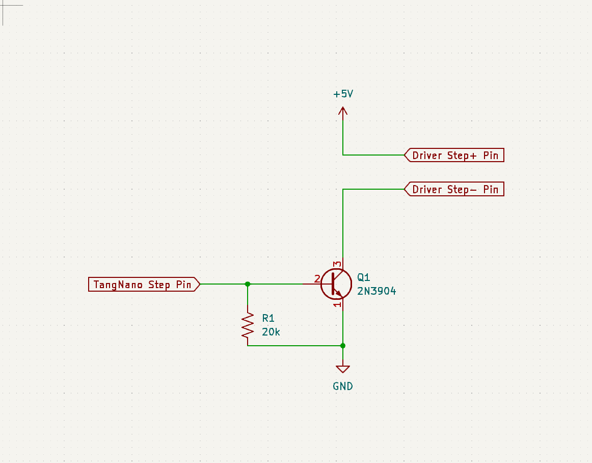
I'm not as familiar with the TX0108E , but another option is to switch the low side instead of the high side. Such as a simple transistor between the - of the driver and GND, if that's an option for your stepper driver. (See image).Just a stab in the dark, but does the TX0108E have capacitors wired to power lines and close to the chip?
A 10 microFarad electrolytic and a 0.1 micro ceramic should do.
I wonder if you're running into voltage drop on the TX0108E if you're switching the high side? I also wonder if the Tang Nano can't push enough current on the 5v rail for your application, maybe provide an external 5v source to VB? Perhaps monitor VB with the scope as well, see how stable that is?
Attachments:
Last edit: 05 Nov 2024 16:03 by digiex_chris.
Please Log in or Create an account to join the conversation.
- mBender
- Offline
- Premium Member
-

Less
More
- Posts: 133
- Thank you received: 15
05 Nov 2024 16:17 #313823
by mBender
The power supply from the Tang is stable. I had that suspicion too and tested it with my oscilloscope. 5V is clean and no power drop.
What I have found out is that the bidirectional level shifter have some weird logic to figure out which side is driving and it seems they create often problems. I even tried to put the output side with a pull up / pull down. No difference.
I think something like a 74ACT245 where you can external control the direction might be better for this application.
Replied by mBender on topic LinuxCNC-RIO - RealtimeIO for LinuxCNC based on FPGA (ICE40 / ECP5)
I thought about the Transistor solution as well. I have actually some transistors laying around, but the fact that the new level shifter should arrive any minute has me stopped that. At least for the moment.
Just a stab in the dark, but does the TX0108E have capacitors wired to power lines and close to the chip?
A 10 microFarad electrolytic and a 0.1 micro ceramic should do.
I'm not as familiar with the TX0108E , but another option is to switch the low side instead of the high side. Such as a simple transistor between the - of the driver and GND, if that's an option for your stepper driver. (See image).
I wonder if you're running into voltage drop on the TX0108E if you're switching the high side? I also wonder if the Tang Nano can't push enough current on the 5v rail for your application, maybe provide an external 5v source to VB? Perhaps monitor VB with the scope as well, see how stable that is?
The power supply from the Tang is stable. I had that suspicion too and tested it with my oscilloscope. 5V is clean and no power drop.
What I have found out is that the bidirectional level shifter have some weird logic to figure out which side is driving and it seems they create often problems. I even tried to put the output side with a pull up / pull down. No difference.
I think something like a 74ACT245 where you can external control the direction might be better for this application.
Please Log in or Create an account to join the conversation.
- meister
- Offline
- Platinum Member
-

Less
More
- Posts: 698
- Thank you received: 428
05 Nov 2024 16:26 #313825
by meister
The deviations are actually only rounding errors, which should be no different with mesa hardware.
Remora does it the same way, only with a little trick, there the PID controller is hidden in the driver and linuxcnc does not show the calculated values but those that were sent.
In the beginning I also had the PID controller in the driver (linuxcnc-component), because it was only a copy of the remora driver, but that is actually just optics.
so far, the position has always been accurate to the step...
tuning is also not necessary if you use stepper
Replied by meister on topic LinuxCNC-RIO - RealtimeIO for LinuxCNC based on FPGA (ICE40 / ECP5)
the pid-loop is necessary with external hardware, as only velocity information can be sent in this way.well, last night I got first movements to work on my iceshield derivative, and got the scale correct. Trying to get my head around the PID settings, I'm a bit lost since I'm normally a stepper guy working with more direct controllers that work similar to parallel port setups, 1 step = 1 step moved, no hunting position. this seems to be treating the fpga as it would treat a servo with encoder feedback. The position doesn't quite reach the commanded position, and it hunts a little, which I find odd for open-loop steppers with no encoder feedback.
Can anyone enlighten me on how to tune this? Is P too high? I have a feeling it maybe should be set to 1.0 instead of the default 250 so there is no gain.
The deviations are actually only rounding errors, which should be no different with mesa hardware.
Remora does it the same way, only with a little trick, there the PID controller is hidden in the driver and linuxcnc does not show the calculated values but those that were sent.
In the beginning I also had the PID controller in the driver (linuxcnc-component), because it was only a copy of the remora driver, but that is actually just optics.
so far, the position has always been accurate to the step...
tuning is also not necessary if you use stepper
The following user(s) said Thank You: digiex_chris
Please Log in or Create an account to join the conversation.
- meister
- Offline
- Platinum Member
-

Less
More
- Posts: 698
- Thank you received: 428
05 Nov 2024 16:32 #313826
by meister
On the Tangbob board I use the TXS0108EPW with pull up/down resistors on the input side.
However, to switch optocouplers in the output stages, for example, you still need a driver like the ones installed on the BOB boards (uln2308), the level shifters are not designed for this
Replied by meister on topic LinuxCNC-RIO - RealtimeIO for LinuxCNC based on FPGA (ICE40 / ECP5)
Just a stab in the dark, but does the TX0108E have capacitors wired to power lines and close to the chip?
A 10 microFarad electrolytic and a 0.1 micro ceramic should do.
I'm not as familiar with the TX0108E , but another option is to switch the low side instead of the high side. Such as a simple transistor between the - of the driver and GND, if that's an option for your stepper driver. (See image).
I wonder if you're running into voltage drop on the TX0108E if you're switching the high side? I also wonder if the Tang Nano can't push enough current on the 5v rail for your application, maybe provide an external 5v source to VB? Perhaps monitor VB with the scope as well, see how stable that is?
I thought about the Transistor solution as well. I have actually some transistors laying around, but the fact that the new level shifter should arrive any minute has me stopped that. At least for the moment.
The power supply from the Tang is stable. I had that suspicion too and tested it with my oscilloscope. 5V is clean and no power drop.
What I have found out is that the bidirectional level shifter have some weird logic to figure out which side is driving and it seems they create often problems. I even tried to put the output side with a pull up / pull down. No difference.
I think something like a 74ACT245 where you can external control the direction might be better for this application.
On the Tangbob board I use the TXS0108EPW with pull up/down resistors on the input side.
However, to switch optocouplers in the output stages, for example, you still need a driver like the ones installed on the BOB boards (uln2308), the level shifters are not designed for this
Please Log in or Create an account to join the conversation.
- Hardware & Machines
- Computers and Hardware
- LinuxCNC-RIO - RealtimeIO for LinuxCNC based on FPGA (ICE40 / ECP5)
Time to create page: 0.356 seconds


