- Hardware & Machines
- Computers and Hardware
- LinuxCNC-RIO - RealtimeIO for LinuxCNC based on FPGA (ICE40 / ECP5)
LinuxCNC-RIO - RealtimeIO for LinuxCNC based on FPGA (ICE40 / ECP5)
- mBender
- Offline
- Premium Member
-

Less
More
- Posts: 133
- Thank you received: 15
07 Nov 2024 18:27 #314028
by mBender
Replied by mBender on topic LinuxCNC-RIO - RealtimeIO for LinuxCNC based on FPGA (ICE40 / ECP5)
Below is the current set up as of last night. Bench testing worked as expected. It goes from there to a Parallel port break out board. This allwos me to use my machine with LinuxCNC and laserGRBL with just changing a plug. I tried to find out the current rating of the 3.3V and 5V power supply of the Tang Nano 9k. According to the
schematics,
it seems like that there is a
TMI7003C
DC/DC Step down, which gets it's 5V directly from the USB C port. If I read it correct, it can supply a max current of 1.5A total. That'a including the power for the FPGA,...It seems like the each Output of the Tang can drive up to 24mA. Which obviusley need to be deducted from the 1.5A plus the other current demands of the FPGA board. Still I believe there is plenty of current to drive secondary operations.The 1.8V needed for Bank 3 is not availbale at FPGA board. I was wondering if I could just use 1 or 2 1.8V outputs, set them pernantley to high and use them as supply voltage for any leverl shifter at Bank3. Opinions?
Attachments:
Please Log in or Create an account to join the conversation.
- digiex_chris
- Offline
- Senior Member
-

Less
More
- Posts: 40
- Thank you received: 11
07 Nov 2024 21:17 #314043
by digiex_chris
I also ended up with a XHC WHB04B-6 wireless MPG that currently satisfies 90% of my control needs, so I don't have a lot of willpower to make a UI that needs a lot of GPIO.
I know that doesn't solve your problem, but just thought I'd mention it for ideas.
Also, a common LM317 is easy to make it output 1.8v from from the 5v input, as another option. 2 capacitors and 2 resistors. It's hard to even burn them out, they shut themselves down with overcurrent.
Replied by digiex_chris on topic LinuxCNC-RIO - RealtimeIO for LinuxCNC based on FPGA (ICE40 / ECP5)
My personal plan if I needed more gpio was to ignore the 1.8v pins and using the 3.3v pins either use a shift register, see if I could add i2c GPIO expansion support such as the mcp23017, or reserve the FPGA purely for estop, home pins, and steppers and use something else for things like MPG controls and such. github.com/wezhunter/ESP32_LinuxCNC_MotionController_RealTime perhaps, since I have a pile of esp32S2's around.Below is the current set up as of last night. Bench testing worked as expected. It goes from there to a Parallel port break out board. This allwos me to use my machine with LinuxCNC and laserGRBL with just changing a plug. I tried to find out the current rating of the 3.3V and 5V power supply of the Tang Nano 9k. According to the schematics, it seems like that there is a TMI7003C DC/DC Step down, which gets it's 5V directly from the USB C port. If I read it correct, it can supply a max current of 1.5A total. That'a including the power for the FPGA,...It seems like the each Output of the Tang can drive up to 24mA. Which obviusley need to be deducted from the 1.5A plus the other current demands of the FPGA board. Still I believe there is plenty of current to drive secondary operations.The 1.8V needed for Bank 3 is not availbale at FPGA board. I was wondering if I could just use 1 or 2 1.8V outputs, set them pernantley to high and use them as supply voltage for any leverl shifter at Bank3. Opinions?
I also ended up with a XHC WHB04B-6 wireless MPG that currently satisfies 90% of my control needs, so I don't have a lot of willpower to make a UI that needs a lot of GPIO.
I know that doesn't solve your problem, but just thought I'd mention it for ideas.
Also, a common LM317 is easy to make it output 1.8v from from the 5v input, as another option. 2 capacitors and 2 resistors. It's hard to even burn them out, they shut themselves down with overcurrent.
Please Log in or Create an account to join the conversation.
- meister
- Offline
- Platinum Member
-

Less
More
- Posts: 689
- Thank you received: 419
08 Nov 2024 10:25 #314071
by meister
Replied by meister on topic LinuxCNC-RIO - RealtimeIO for LinuxCNC based on FPGA (ICE40 / ECP5)
You need only to lower the voltage a little bit for the Level-Shifter with a Diode or two Resistors,
the FPGA can handle up to 3.3V input and the Level-Shifter need to detect 1.8V as high.
the FPGA can handle up to 3.3V input and the Level-Shifter need to detect 1.8V as high.
Please Log in or Create an account to join the conversation.
- mBender
- Offline
- Premium Member
-

Less
More
- Posts: 133
- Thank you received: 15
10 Nov 2024 00:23 #314159
by mBender
Replied by mBender on topic LinuxCNC-RIO - RealtimeIO for LinuxCNC based on FPGA (ICE40 / ECP5)
I am trying to get Classicladder to work. When I start the machine, I get the following error. I can confirm that Classic Ladder on the same PC in my old LinuxCnc configuration (parallel port instead of FPGA) works. I even tried to copy all the classicladder lines from the parallel port .hal file, but still get the same error.
Shared memory conflict or RT component not loaded!
ERROR CLASSICLADDER- Ladder memory allocation error
Shared memory conflict or RT component not loaded!
ERROR CLASSICLADDER- Ladder memory allocation error
Please Log in or Create an account to join the conversation.
- mBender
- Offline
- Premium Member
-

Less
More
- Posts: 133
- Thank you received: 15
10 Nov 2024 02:30 #314169
by mBender
Replied by mBender on topic LinuxCNC-RIO - RealtimeIO for LinuxCNC based on FPGA (ICE40 / ECP5)
I got a step ahead. If start Linuxcnc with the error, open the classicladder editor and load the program again, then close linuxcnc and start it again, classicladder starts with no error for one time! If I close linuxcnc and start it again, it doesn't work and I have to do the same procedure again.
Either way Classic ladder starting or not, the Modbus is still not working, it seems like for whatever reason it does not read the USB to RS485 adapter.
I confirmed, that when I start the old configuration, it starts and starts reading the modbus. Hal Configurations for modbus are in both cases identical.
Please Log in or Create an account to join the conversation.
- mBender
- Offline
- Premium Member
-

Less
More
- Posts: 133
- Thank you received: 15
10 Nov 2024 03:13 - 10 Nov 2024 13:59 #314171
by mBender
Replied by mBender on topic LinuxCNC-RIO - RealtimeIO for LinuxCNC based on FPGA (ICE40 / ECP5)
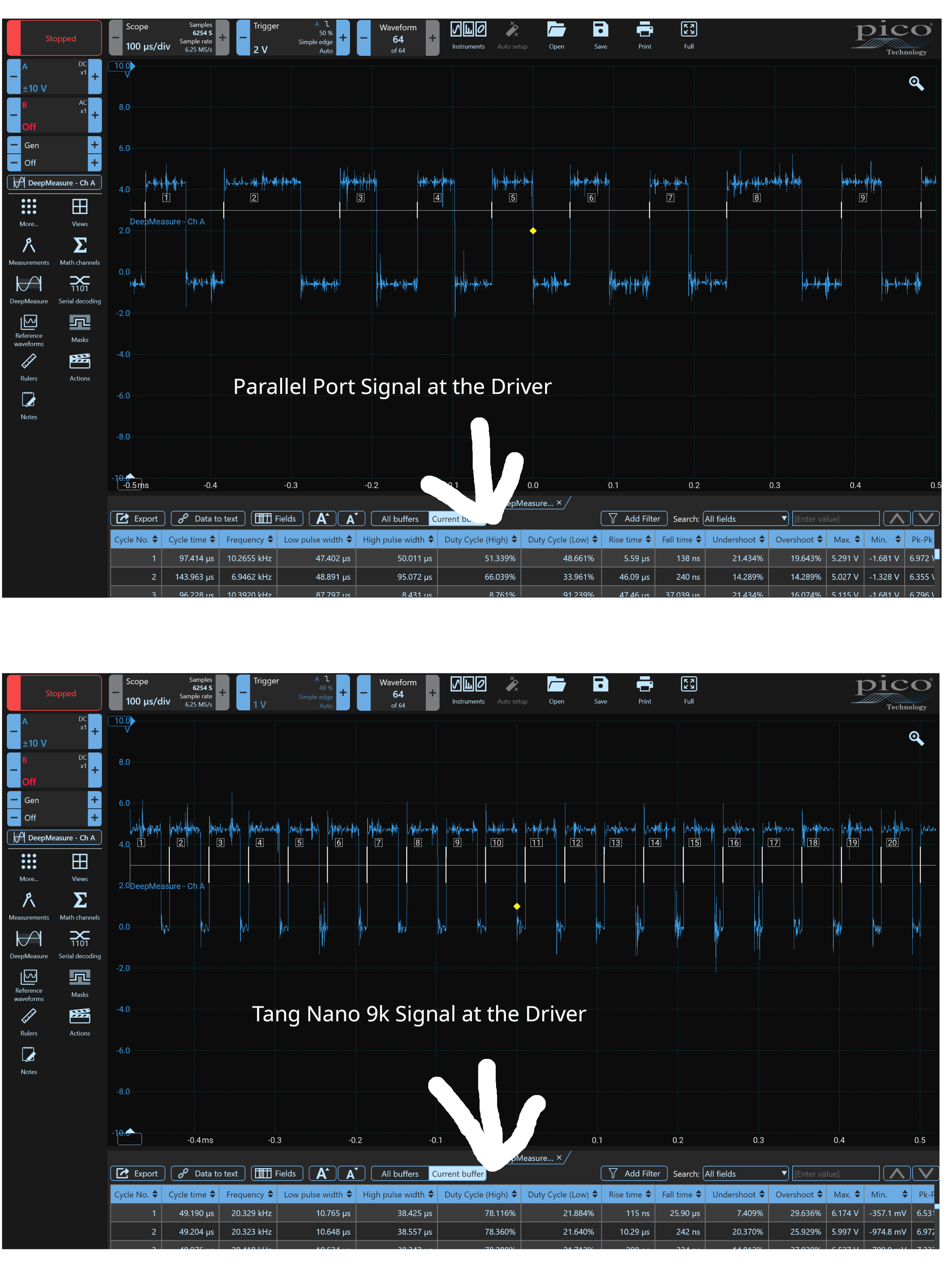
And another interesting thing. The Tang is performing way better as my parallel port! I can go high speed with much more microstepping. The motors sound better, but somehow I hit a wall when I wanted to go higher speeds. I am not sure what the reason for this is. If I run with the Tang, I can go up to 2000mm/min (400rpm on my motors) with my Y axis. No matter if I have 10 or 16 microsteps. If I go over the that speed the motor go for like 50mm than they start sounding weird until one of the 2 motors stalls. I first thought that was a mechanical issue and detached the gantry, but still same behavior. I checked with my osciloscope the output of the Tang, the level shifter, the BOB and finally I measured directly at the drives. All seems good. My drives need 2ns low period before the detect the next raising edge. All I measured was within the tolerance of the drives...
I almost gave up since it seems like independent from the microsteps. Then I tried my parallel port set up again and pushed as much as I could. I had to go down to 10 microsteps again and was able to achieve without the stalling around 2700mm/min. Could not go higher due to cycle time limitations, then I got a joint following error in linuxcnc.
I measured again at the drives and saw that the duty cycle high and low of the parallel port signal are almost equal at 50%. The tang produces 80% 20%. I believe this could be a reason why I can't go higher. Is it possible? and if so, change be changed?
In the picture of the parallel port you can see the jitter. Where the Tang performance is much better!
Attachments:
Last edit: 10 Nov 2024 13:59 by mBender.
Please Log in or Create an account to join the conversation.
- meister
- Offline
- Platinum Member
-

Less
More
- Posts: 689
- Thank you received: 419
11 Nov 2024 07:42 #314229
by meister
Replied by meister on topic LinuxCNC-RIO - RealtimeIO for LinuxCNC based on FPGA (ICE40 / ECP5)
the stepgen from rio also has a duty cycle of 50%,
try measuring the signal at the FPGA pin
try measuring the signal at the FPGA pin
Please Log in or Create an account to join the conversation.
- digiex_chris
- Offline
- Senior Member
-

Less
More
- Posts: 40
- Thank you received: 11
11 Nov 2024 22:04 #314286
by digiex_chris
Replied by digiex_chris on topic LinuxCNC-RIO - RealtimeIO for LinuxCNC based on FPGA (ICE40 / ECP5)
I wonder if at that speed you're getting near the max speed of the level shifter? How does the tang look at the same speed as the paraport?
Please Log in or Create an account to join the conversation.
- mBender
- Offline
- Premium Member
-

Less
More
- Posts: 133
- Thank you received: 15
12 Nov 2024 03:42 #314299
by mBender
Replied by mBender on topic LinuxCNC-RIO - RealtimeIO for LinuxCNC based on FPGA (ICE40 / ECP5)
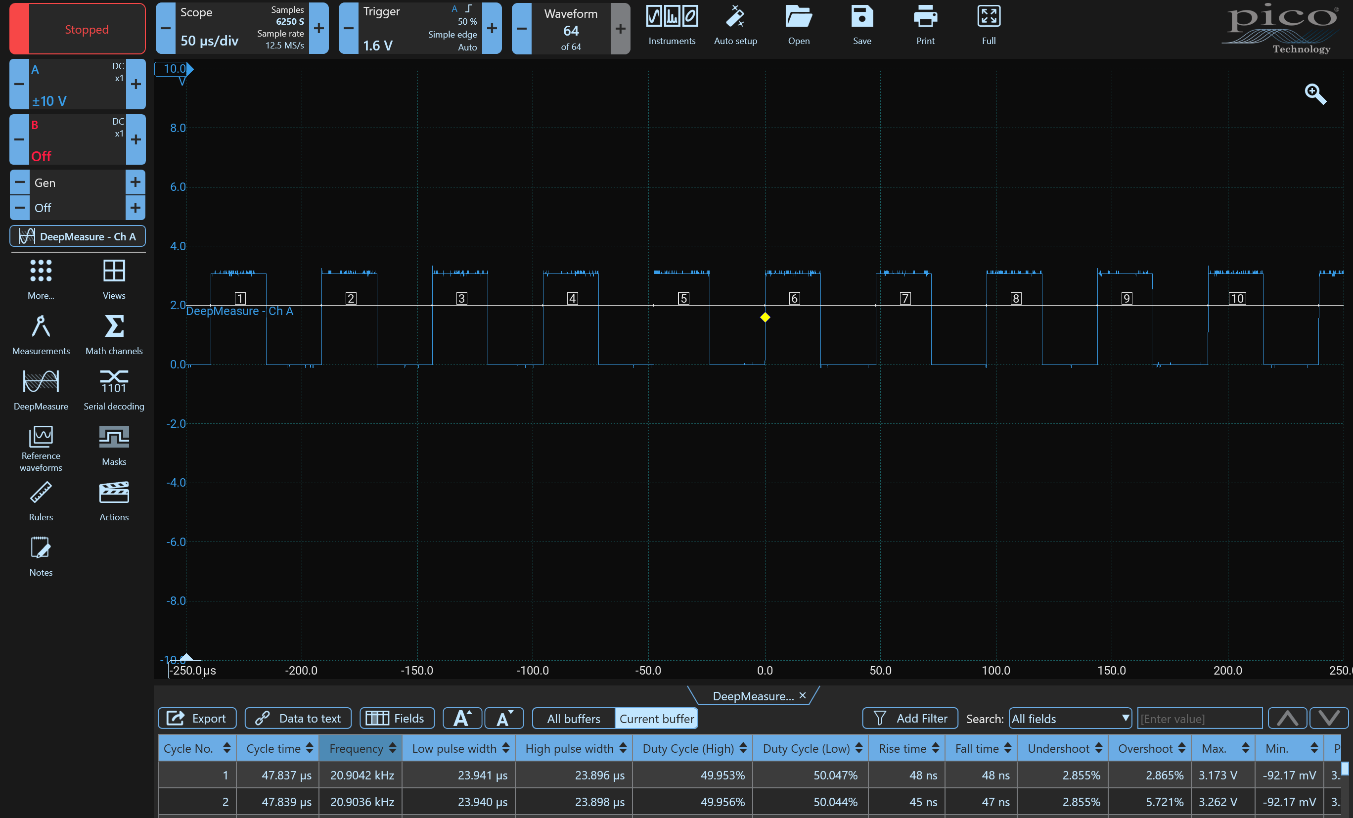
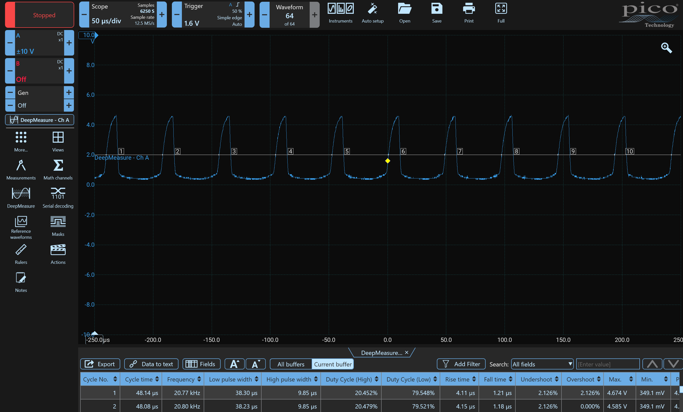
Hmm, I must have made a mistake when measuring the signals. The Tang gives out a perfect 50% duty cycle. I was sure that the level shifter made the same. however they did not. The level shifters make something weird out of it. The level shifter have EL817 coupler on them. The
datasheet
shows cut off frequency fc =80khz. If I read that right I should not even be around 25% of what they should be able to do. They do have an LED, I wonder if a pulldown resistor would help???
I think @meister said, that I could connected the breakout board directly to the outputs of the Tang. I might try that.
I think @meister said, that I could connected the breakout board directly to the outputs of the Tang. I might try that.
Attachments:
Please Log in or Create an account to join the conversation.
- mBender
- Offline
- Premium Member
-

Less
More
- Posts: 133
- Thank you received: 15
12 Nov 2024 03:47 #314300
by mBender
Replied by mBender on topic LinuxCNC-RIO - RealtimeIO for LinuxCNC based on FPGA (ICE40 / ECP5)
This is all kind of weird. I tested at the weekend the motors with different microsteps. If the levelshifter are the limits, with less microsteps I should have been able to run the motors faster, or? I am pretty sure that this wasn't the case. The motors stalled around 2100mm/min. I set up the machine that it would to max 1950mm/min. Tonight when I tested it again the motors stalled even at 1950mm/min.
Also I noticed that when I am not moving the axis, a stepsignal was created. The motor did not move but you could hear and see that the Tang was sending step signals. I increased the mircosteps from 10 to 16 in compare to the last time I tried the machine. Has that something to do with the set up of Linuxcnc?
I have to say that the wiring is currently breadboard style. I guess that won't help with 20khz plus signals.
Please Log in or Create an account to join the conversation.
- Hardware & Machines
- Computers and Hardware
- LinuxCNC-RIO - RealtimeIO for LinuxCNC based on FPGA (ICE40 / ECP5)
Time to create page: 0.188 seconds


