- Hardware & Machines
- Computers and Hardware
- LinuxCNC-RIO - RealtimeIO for LinuxCNC based on FPGA (ICE40 / ECP5)
LinuxCNC-RIO - RealtimeIO for LinuxCNC based on FPGA (ICE40 / ECP5)
- meister
- Offline
- Platinum Member
-

Less
More
- Posts: 745
- Thank you received: 465
02 Jan 2025 08:25 #317863
by meister
Replied by meister on topic LinuxCNC-RIO - RealtimeIO for LinuxCNC based on FPGA (ICE40 / ECP5)
the normal linuxcnc channel
discord.com/channels/970073318357078036/970073318810075149
discord.com/channels/970073318357078036/970073318810075149
Please Log in or Create an account to join the conversation.
- epineh
- Offline
- Senior Member
-

Less
More
- Posts: 76
- Thank you received: 27
02 Jan 2025 10:06 #317866
by epineh
Replied by epineh on topic LinuxCNC-RIO - RealtimeIO for LinuxCNC based on FPGA (ICE40 / ECP5)
OK so to answer my own previous question basically I'm stupid, I hadn't set ownership to my user account, so Linuxcnc couldn't write to the var file, and most likely create it in the first place, which is why it was missing.
I had thought I'd done it but obviously I hadn't or maybe did a typo at the time. I followed the Docker install instructions as per the wiki instructions if anybody else is having the same issue.
Big thanks to Meister for creating this and thanks to everybody else supporting.
Russell.
I had thought I'd done it but obviously I hadn't or maybe did a typo at the time. I followed the Docker install instructions as per the wiki instructions if anybody else is having the same issue.
Big thanks to Meister for creating this and thanks to everybody else supporting.
Russell.
The following user(s) said Thank You: meister
Please Log in or Create an account to join the conversation.
- kzali
- Offline
- Junior Member
-

Less
More
- Posts: 35
- Thank you received: 12
23 Jan 2025 22:49 #319737
by kzali
Replied by kzali on topic LinuxCNC-RIO - RealtimeIO for LinuxCNC based on FPGA (ICE40 / ECP5)
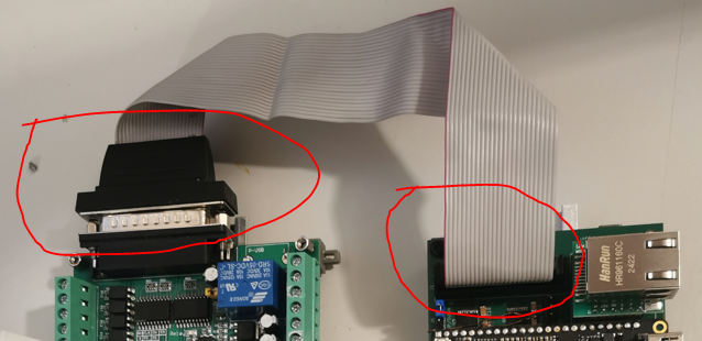
This maybe a silly question bit is there a wiring diagram for the ribbon connector of the DB25's
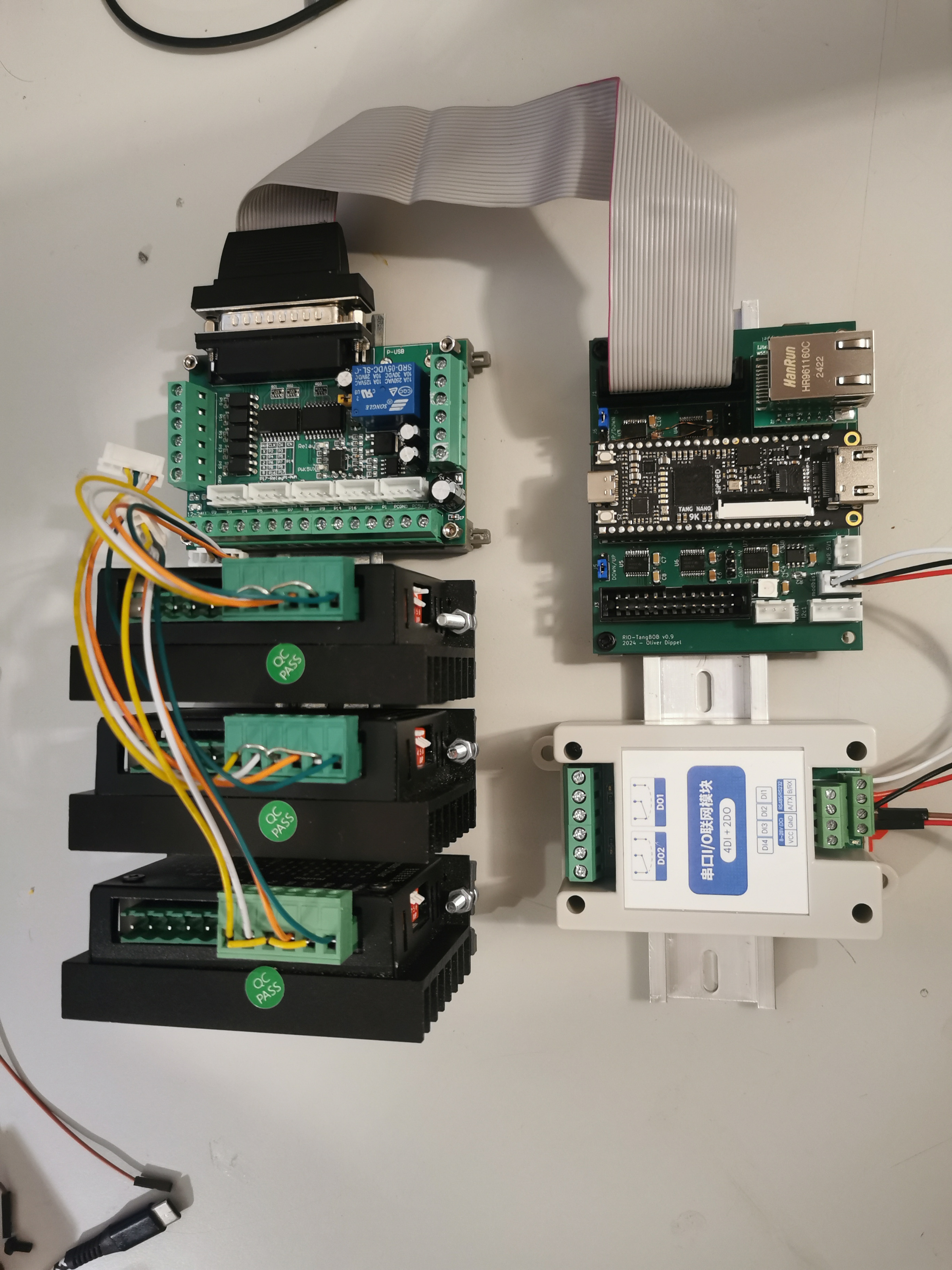
Can't recommend this set-up enough. For those who aren't particularly interested in engineering hardware and want a Snap-On Ready Kit, it just won't get any better than that. That'll do 50meg, prolly capable of more. Oliver did it all for grab github.com/multigcs/rio-tangbob
Flash the bitstream over, plug-in a shielded 100mb cat6, and be done!!
Attachments:
Please Log in or Create an account to join the conversation.
- Cant do this anymore bye all
-

- Offline
- Platinum Member
-
Less
More
- Posts: 1200
- Thank you received: 425
24 Jan 2025 04:19 #319745
by Cant do this anymore bye all
Replied by Cant do this anymore bye all on topic LinuxCNC-RIO - RealtimeIO for LinuxCNC based on FPGA (ICE40 / ECP5)
It's a one to one connection. Pin 1 to Pin 1 etc. The wire with the red tracer is pin 1.
The following user(s) said Thank You: meister
Please Log in or Create an account to join the conversation.
- kzali
- Offline
- Junior Member
-
Less
More
- Posts: 35
- Thank you received: 12
24 Jan 2025 06:40 #319750
by kzali

Replied by kzali on topic LinuxCNC-RIO - RealtimeIO for LinuxCNC based on FPGA (ICE40 / ECP5)
I have a 26 Way IDC Line Socket from jaycar here in Sydney image is below but it has no pin numbers marked. Searched like mad but no luck. Your help will be much appreciated. The D25 IDC has numberings marked!It's a one to one connection. Pin 1 to Pin 1 etc. The wire with the red tracer is pin 1.
Attachments:
Please Log in or Create an account to join the conversation.
- Cant do this anymore bye all
-
- Offline
- Platinum Member
-
Less
More
- Posts: 1200
- Thank you received: 425
24 Jan 2025 08:33 #319751
by Cant do this anymore bye all
Replied by Cant do this anymore bye all on topic LinuxCNC-RIO - RealtimeIO for LinuxCNC based on FPGA (ICE40 / ECP5)
Plug it into the male header on the board.
Where it aligns with Pin 1 on the board, that will be Pin 1.
Where it aligns with Pin 1 on the board, that will be Pin 1.
The following user(s) said Thank You: kzali
Please Log in or Create an account to join the conversation.
- cakeslob
- Offline
- Platinum Member
-
Less
More
- Posts: 926
- Thank you received: 278
24 Jan 2025 14:46 #319757
by cakeslob

Replied by cakeslob on topic LinuxCNC-RIO - RealtimeIO for LinuxCNC based on FPGA (ICE40 / ECP5)
The following user(s) said Thank You: kzali, Cant do this anymore bye all
Please Log in or Create an account to join the conversation.
- Tim Bee
- Offline
- Junior Member
-
Less
More
- Posts: 24
- Thank you received: 7
25 Jan 2025 08:49 #319807
by Tim Bee
Replied by Tim Bee on topic LinuxCNC-RIO - RealtimeIO for LinuxCNC based on FPGA (ICE40 / ECP5)
Dear meister:
When I tested RIO, I was a little confused。
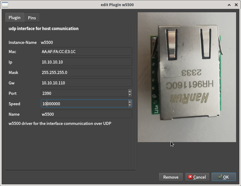
1. I set spi clk is 10Mhz, but 6.4Mhz actually

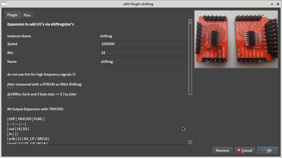
2. and I set shiftreg clk 1Mhz, but 323Khz actually
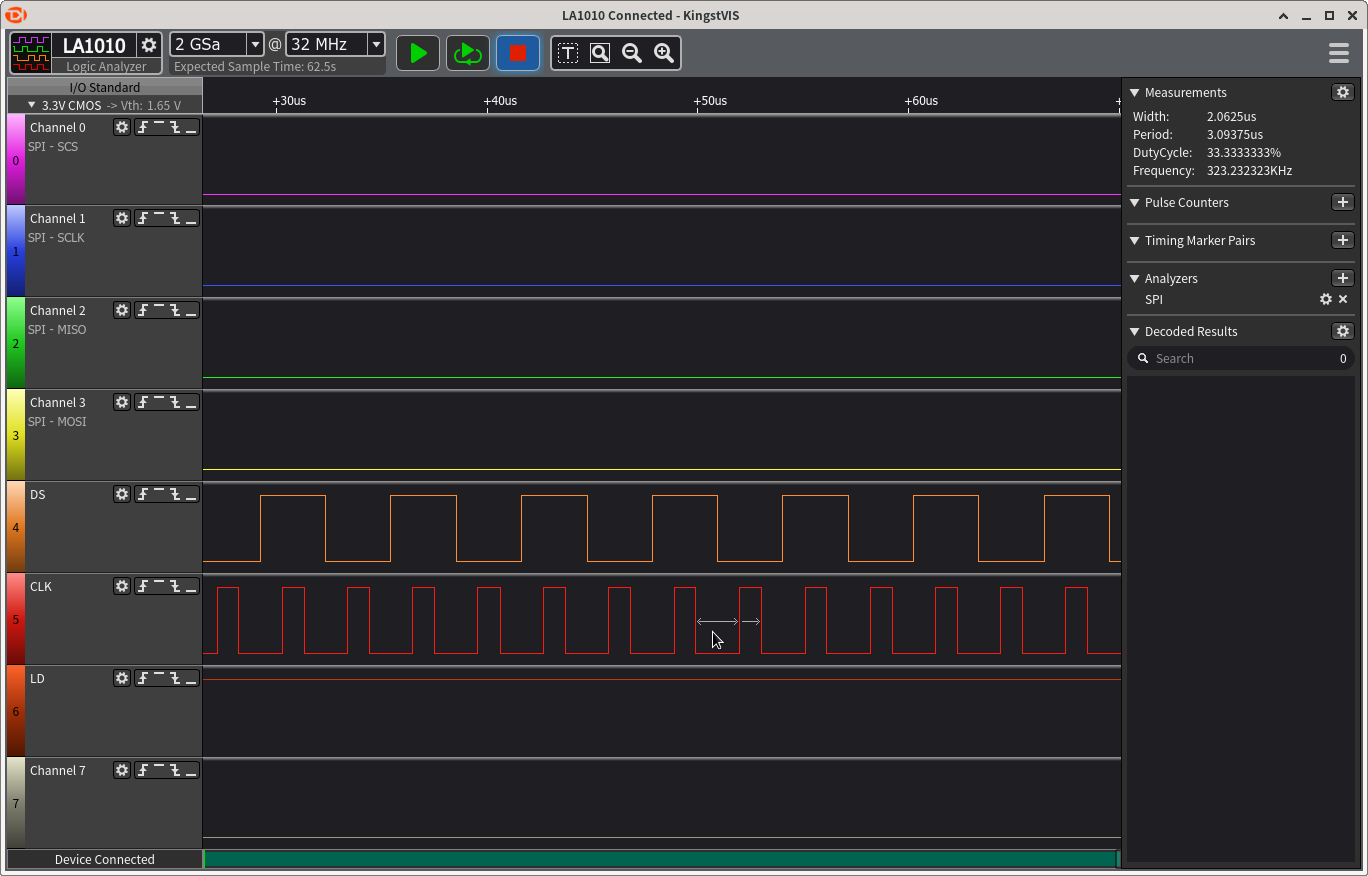
FPGA is ice40up5k
Is that correct?Thank you.
Tim
When I tested RIO, I was a little confused。
1. I set spi clk is 10Mhz, but 6.4Mhz actually
2. and I set shiftreg clk 1Mhz, but 323Khz actually
FPGA is ice40up5k
Is that correct?Thank you.
Tim
Attachments:
The following user(s) said Thank You: meister
Please Log in or Create an account to join the conversation.
- meister
- Offline
- Platinum Member
-
Less
More
- Posts: 745
- Thank you received: 465
25 Jan 2025 15:50 #319823
by meister
Replied by meister on topic LinuxCNC-RIO - RealtimeIO for LinuxCNC based on FPGA (ICE40 / ECP5)
Hi Tim,
your measurements are correct,
the code is wrong
I have fixed the shiftreg plugin,
but the 6.4Mhz of the w5500 are correct,
more is not possible with the ice40up5k on 30Mhz clock.
Thanks !
your measurements are correct,
the code is wrong
I have fixed the shiftreg plugin,
but the 6.4Mhz of the w5500 are correct,
more is not possible with the ice40up5k on 30Mhz clock.
Thanks !
The following user(s) said Thank You: Tim Bee
Please Log in or Create an account to join the conversation.
- Tim Bee
- Offline
- Junior Member
-
Less
More
- Posts: 24
- Thank you received: 7
26 Jan 2025 14:50 #319890
by Tim Bee
Replied by Tim Bee on topic LinuxCNC-RIO - RealtimeIO for LinuxCNC based on FPGA (ICE40 / ECP5)
HI meister:
Thanks for your reply.
I will test that later.thank you very much

and I have a promblem about w5500 spi clk:
I tested the joint.n.f-error seem biger than mesa card,
my PID is: P=1000 I=0 D=0,when i jog x axis,the joint.0.f-error is about 0.05mm
if i set P=0,I=0,D=0,when i jog x axis Exceed about 800mm,the "joint 0 following error" pop up(I set FERROR=3)
The difference between the feedback value and the command value is getting bigger and bigger
I know when i used a low speed run the axis,the f-error is good for me, I'm just a little curious, it's related to the spi clock?

Thanks
Tim
Thanks for your reply.
I will test that later.thank you very much
and I have a promblem about w5500 spi clk:
I tested the joint.n.f-error seem biger than mesa card,
my PID is: P=1000 I=0 D=0,when i jog x axis,the joint.0.f-error is about 0.05mm
if i set P=0,I=0,D=0,when i jog x axis Exceed about 800mm,the "joint 0 following error" pop up(I set FERROR=3)
The difference between the feedback value and the command value is getting bigger and bigger
I know when i used a low speed run the axis,the f-error is good for me, I'm just a little curious, it's related to the spi clock?
Thanks
Tim
Please Log in or Create an account to join the conversation.
- Hardware & Machines
- Computers and Hardware
- LinuxCNC-RIO - RealtimeIO for LinuxCNC based on FPGA (ICE40 / ECP5)
Time to create page: 0.599 seconds