
- Posts: 1635
- Thank you received: 595
Schaublin 125-CNC retrofit.
- RotarySMP
- Offline
- Platinum Member
-

Less
More
5 years 1 month ago - 5 years 1 month ago #221073
by RotarySMP
Replied by RotarySMP on topic Schaublin 125-CNC retrofit.
Here is the latest...
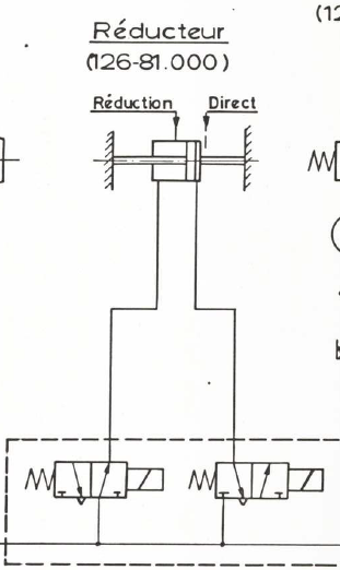
I am not sure whether I can use a Festo CPV 10 type C valve instead of a type H.


If the two valves within it are not mechanically connected, and can be electrically commanded to opposite positions, then I could use a Type C valve I already have to control the back gear. Otherwise do any of you have a stash of CPV 10 valves on your "that might come in handy" shelf? Specifically a type J, H and L blank plate?
... Oh, I just read that sub text to the type H and it seems a type M also does that job. I have three of them. I wonder if they used two separate valves on the back gear, to enable a neutral position?
Mark
I am not sure whether I can use a Festo CPV 10 type C valve instead of a type H.
If the two valves within it are not mechanically connected, and can be electrically commanded to opposite positions, then I could use a Type C valve I already have to control the back gear. Otherwise do any of you have a stash of CPV 10 valves on your "that might come in handy" shelf? Specifically a type J, H and L blank plate?
... Oh, I just read that sub text to the type H and it seems a type M also does that job. I have three of them. I wonder if they used two separate valves on the back gear, to enable a neutral position?
Mark
Last edit: 5 years 1 month ago by RotarySMP.
The following user(s) said Thank You: tommylight, anfänger, DoWerna
Please Log in or Create an account to join the conversation.
- spumco
- Offline
- Platinum Member
-
Less
More
- Posts: 2180
- Thank you received: 905
5 years 1 month ago #221128
by spumco
Looking over your video with the pneumatic diagram, it looks like they used single coil 3/2 valves for everything (and not double-coil single spool 5-ways). I bet that's just to simplify the mechanical installation (given the size of those solenoid valves) and not to enable a 'neutral' feature.
You could check if there is an intended neutral position by reviewing the relay logic on whatever is controlling the gearbox valves. If it's an OR relay logic then you know they didn't intend an intermediate position and used separate valves because they're the same everywhere else.
I'm frequently wrong about a great many things, but I don't think there's an intended neutral position:
-Ralph
Replied by spumco on topic Schaublin 125-CNC retrofit.
[Thanks for the vids, BTW. Very entertaining and educational.]I wonder if they used two separate valves on the back gear, to enable a neutral position?
Looking over your video with the pneumatic diagram, it looks like they used single coil 3/2 valves for everything (and not double-coil single spool 5-ways). I bet that's just to simplify the mechanical installation (given the size of those solenoid valves) and not to enable a 'neutral' feature.
You could check if there is an intended neutral position by reviewing the relay logic on whatever is controlling the gearbox valves. If it's an OR relay logic then you know they didn't intend an intermediate position and used separate valves because they're the same everywhere else.
I'm frequently wrong about a great many things, but I don't think there's an intended neutral position:
- There doesn't appear to be a position sensor
- (assumption) There's no spring return to neutral in the gearbox, so the only way to get to a center neutral is to pressure up both sides at once and hope there's no pressure differential that would cause the cylinder to drift
- Schaublin used two separate valves to move the gearbox, when they could have used a single valve combined with a spring-return cylinder connected to the gearbox. I know there are systems where the design engineer doesn't like, doesn't trust, or whatever a spring-return system and goes with positive movement in both directions via air. Less chance of a state change during loss of air pressure.
-Ralph
The following user(s) said Thank You: RotarySMP
Please Log in or Create an account to join the conversation.
- RotarySMP
- Offline
- Platinum Member
-
Less
More
- Posts: 1635
- Thank you received: 595
5 years 1 month ago - 5 years 1 month ago #221138
by RotarySMP
Replied by RotarySMP on topic Schaublin 125-CNC retrofit.
Thanks Ralph, that is an excellent analysis.
Since Schaublin used 4/2's for collet closer and tailstock, you have to wonder why they did the back gear with 2x 3/2's rather than another 4/2. It cant have been cost!I dont have any access to the control logic, as that is hard coded into the old controller, but just took another look through the manual, and see no reference to a neutral position. I think I was confusing braked/unbraked.
It looks like the modern way to do the reversing of a single actuator is with a 5/2 rather than 2x 3/2's. It also turns out I have plenty of type J valves. The hook looks much shorter on most of them (different font on the older ones?) , so I thought they were I's, but a viewer pointed out from the part number that they are J's. So I also have the one I need for the tailstock. and can use one of them for the back gear as well, instead of controlling both valves of a 2x 3/2 C or H. This way I can control the back gear from a single Mesa Pin rather than two.
Mark
Edit...
I just took another look at the back gear valves, and this system would default to back gear (low speed) on initialisation. Looks like a safety feature. That would then be a Type M instead of J.
Mark
Last edit: 5 years 1 month ago by RotarySMP.
Please Log in or Create an account to join the conversation.
- spumco
- Offline
- Platinum Member
-
Less
More
- Posts: 2180
- Thank you received: 905
5 years 1 month ago - 5 years 1 month ago #221167
by spumco
Replied by spumco on topic Schaublin 125-CNC retrofit.
The reason I got to thinking about your pneumatic conversion is that I'm literally in the middle of setting up the air system on my mill rebuild while watching your video.
Question - and this is from a novice, not someone experienced - is there a significant flow value difference between the original valves and the Festo Legos? And does it make a difference?
I ask because I am more or less doing mine from scratch and could have grabbed some ebay modular valves like yours, but I just went with 'normal' valves on a manifold. It looked like the snap-together modular types were quite a bit lower flow than the usual suspects.
Edit - ok, I see that you can get the modular ones in larger sizes/series from every manufacturer.
Edit 2 - I don't recognize the symbol on the collet closer valve on your OEM diagram. Looks like a double-solenoid, but the little symbol to the left of the left solenoid...is that a latching symbol? And there only appears to be one solenoid coil on that valve in your video...? Just trying to learn a bit more about air systems and why things are designed the way they are.
Thanks,
Ralph
Last edit: 5 years 1 month ago by spumco.
Please Log in or Create an account to join the conversation.
- RotarySMP
- Offline
- Platinum Member
-
Less
More
- Posts: 1635
- Thank you received: 595
5 years 1 month ago - 5 years 1 month ago #221177
by RotarySMP
Replied by RotarySMP on topic Schaublin 125-CNC retrofit.
Hi Ralph,
When I received the valve terminal, I was surprised how small it was, and was also wondering whether there would be sufficient flow, but if you look at what Schaublin did, the rigid tubes out of the flow divider are tiny. Like 1/4" , ~6mm OD tubing, so I doubt that is going to be more restrictive on the Festo.
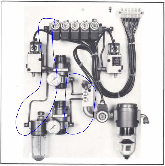
The collet closer is the larger piston in my system, but it is also not a system I will be running fully automated, as that would require a bar puller and bar feeding system. So it doesn't matter if it takes 1/4 sec or 4 sec to close a collet in my use case.
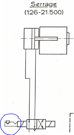
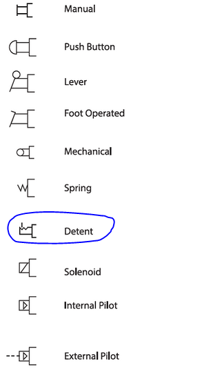
Do you mean this? I think the Schaublin symbols are pre ISO standard. I interpret that as meaning it is bi-stabile and the valve spool remains in whatever location it is left in, until next commanded. But could be wrong there.
Mark
Edit... I found this...
When I received the valve terminal, I was surprised how small it was, and was also wondering whether there would be sufficient flow, but if you look at what Schaublin did, the rigid tubes out of the flow divider are tiny. Like 1/4" , ~6mm OD tubing, so I doubt that is going to be more restrictive on the Festo.
The collet closer is the larger piston in my system, but it is also not a system I will be running fully automated, as that would require a bar puller and bar feeding system. So it doesn't matter if it takes 1/4 sec or 4 sec to close a collet in my use case.
Do you mean this? I think the Schaublin symbols are pre ISO standard. I interpret that as meaning it is bi-stabile and the valve spool remains in whatever location it is left in, until next commanded. But could be wrong there.
Mark
Edit... I found this...
Last edit: 5 years 1 month ago by RotarySMP.
The following user(s) said Thank You: tommylight
Please Log in or Create an account to join the conversation.
- spumco
- Offline
- Platinum Member
-
Less
More
- Posts: 2180
- Thank you received: 905
5 years 1 month ago #221236
by spumco
Replied by spumco on topic Schaublin 125-CNC retrofit.
Thanks, Mark. Yes, that detent symbol was exactly what I was wondering about - makes perfect sense for a collet closer.
-R
-R
Please Log in or Create an account to join the conversation.
Time to create page: 1.393 seconds