Planning - Bridgeport Interact 1 linuxCNC Retrofit
- andypugh
-

- Offline
- Moderator
-

Less
More
- Posts: 19863
- Thank you received: 4636
09 Feb 2016 16:40 #69860
by andypugh
It's actually quite easy, you just need to use one of the motion.spindle-speed-out-*-abs pins:
linuxcnc.org/docs/2.7/html/man/man9/motion.9.html
Replied by andypugh on topic Planning - Bridgeport Interact 1 linuxCNC Retrofit
Now I'm off to read Hal and tutorials on how to implement these changes. I'm thinking that to limit the GPIO to only 0-10V will be difficult for me to get my head around. I'm just now -barely- starting to understand how HAL works.
It's actually quite easy, you just need to use one of the motion.spindle-speed-out-*-abs pins:
linuxcnc.org/docs/2.7/html/man/man9/motion.9.html
Please Log in or Create an account to join the conversation.
- cncnoob1979
-
 Topic Author
- Offline
- Platinum Member
-

Less
More
- Posts: 403
- Thank you received: 75
10 Feb 2016 02:22 - 10 Feb 2016 02:27 #69901
by cncnoob1979
Replied by cncnoob1979 on topic Planning - Bridgeport Interact 1 linuxCNC Retrofit
Since I had everything set for the MODBUS hy_VFD I decided to give it another go.
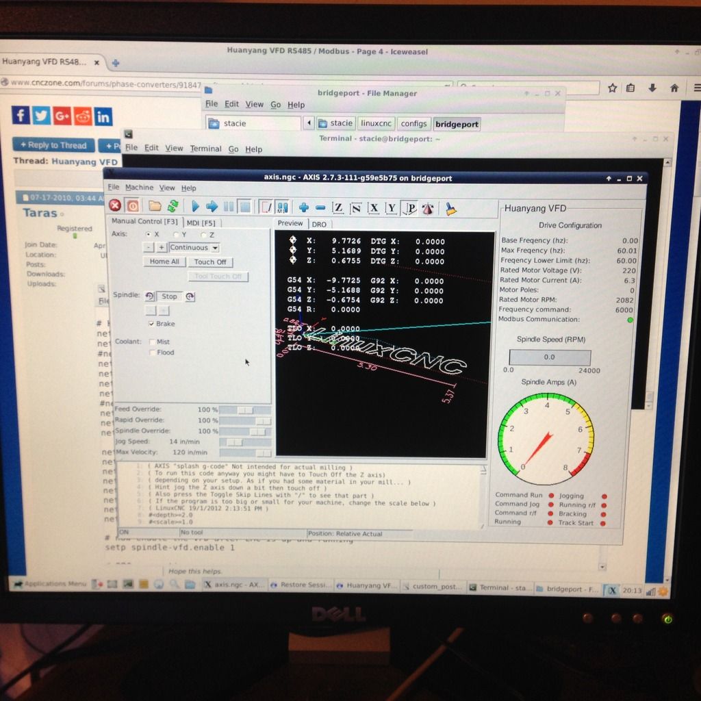
I have it working basically as an off/on reverse switch. I may change it down the road. The recent changes pushed to the git for hy_vfd [sept 2015ish] changed pin names and made this somewhat more difficult.
Had to comment out each item that made me crash and comeback to edit the pins.
Good thing I'm hardheaded as my wife would say. After completing it, I was thinking that it was rather easy.
You don't know, what you don't know.
Anyone looking for details on the setup just ask me I'll do my best to explain what I had to go through.
Last edit: 10 Feb 2016 02:27 by cncnoob1979.
Please Log in or Create an account to join the conversation.
- cncnoob1979
-
Topic Author
- Offline
- Platinum Member
-
Less
More
- Posts: 403
- Thank you received: 75
14 Feb 2016 17:25 - 14 Feb 2016 17:59 #70123
by cncnoob1979
Replied by cncnoob1979 on topic Planning - Bridgeport Interact 1 linuxCNC Retrofit
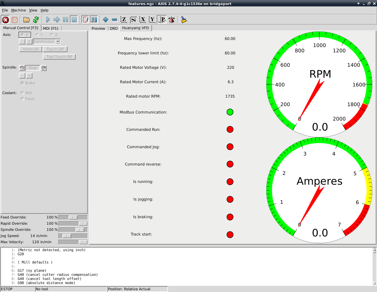
I embedded the VFD into a tab, edited a few things that user "vre" had created. I like it the way it is setup now, im thinking about making the dials into horizontal bars instead.
Now I have a question. Not being a programmer and still very new, I would like to know if it is possible for:
1)Pause any movement/program
2)Linuxcnc to prompt a user with commanded spindle speed [either from g-code or MDI command]
3)Acknowledgement "OK" or Cancel
4)IF OK, then continue with program
5)IF Cancel, stop program
This would allow me to set the spindle speed manually, I am using a variable speed head.
I have read about how to implement variables using user M-Code, but I'm not sure if this would be what I would need?
motion.spindle-inhibit? Perhaps?
Does anyone know where to point me to? I'm not sure what to search to find the information im looking for. Ive tried Google but so far nothing has came up that I think would apply.
How to prompt a user for input to set a variable
Spindle Control with gear change
I have looked at a somethings posted by Andy with the spindle motion out pin, it would seem that I could place something in-between spindle command and every time the spindle is commanded, send that to a user as a prompt.
Given that multiple people have to manually change spindle speeds to accommodate milling/lathe I feel as if this is already implemented and I'm over looking it somewhere. I wouldn't think everyone has an encoder on their spindle")
Sorry if im not using proper terminology, Im getting there!
Now I have a question. Not being a programmer and still very new, I would like to know if it is possible for:
1)Pause any movement/program
2)Linuxcnc to prompt a user with commanded spindle speed [either from g-code or MDI command]
3)Acknowledgement "OK" or Cancel
4)IF OK, then continue with program
5)IF Cancel, stop program
This would allow me to set the spindle speed manually, I am using a variable speed head.
I have read about how to implement variables using user M-Code, but I'm not sure if this would be what I would need?
motion.spindle-inhibit? Perhaps?
Does anyone know where to point me to? I'm not sure what to search to find the information im looking for. Ive tried Google but so far nothing has came up that I think would apply.
How to prompt a user for input to set a variable
Spindle Control with gear change
I have looked at a somethings posted by Andy with the spindle motion out pin, it would seem that I could place something in-between spindle command and every time the spindle is commanded, send that to a user as a prompt.
Given that multiple people have to manually change spindle speeds to accommodate milling/lathe I feel as if this is already implemented and I'm over looking it somewhere. I wouldn't think everyone has an encoder on their spindle
Sorry if im not using proper terminology, Im getting there!
Last edit: 14 Feb 2016 17:59 by cncnoob1979.
Please Log in or Create an account to join the conversation.
- csbrady
- Offline
- Senior Member
-

Less
More
- Posts: 72
- Thank you received: 10
14 Feb 2016 22:14 #70132
by csbrady
Replied by csbrady on topic Planning - Bridgeport Interact 1 linuxCNC Retrofit
cncnoob,
Forgive me, but I don't see why you would want to do it this way. You can set the speed via the VFD and there is no need to use the manual speed control. The VFD gives you plenty of range and can easily be controlled directly from the controller. You already have the modbus interface working so it should not be difficult to manage the speed. This way you just set the speed in the gcode and your done.
I never touch the manual speed control on my machine. It's much more convenient to manage it from the controller.
Please Log in or Create an account to join the conversation.
- cncnoob1979
-
Topic Author
- Offline
- Platinum Member
-
Less
More
- Posts: 403
- Thank you received: 75
15 Feb 2016 00:31 - 15 Feb 2016 01:00 #70139
by cncnoob1979
Replied by cncnoob1979 on topic Planning - Bridgeport Interact 1 linuxCNC Retrofit
csbrady,
Hey! Thanks for the response, I know you have to be scratching you head on my approach. The reason I want to do it this way is because:
Not using the VFD speed control reasons:
1) Using the system as it was designed. I also have a working speed setup with the pneumatic speed rotary controlled via 7i77, and manual switches.
2) I do not have to worry about torque curves or limitations associated with our variable system.
3) I do not have to worry about cooling of the motor/over stressing the motor via exceeding 60hz (over or under)
4) With variable speed, I am not at 1:1 ratio, therefore without a spindle encoder, I do not know what my true spindle speed is.
5) Without the true spindle speed it would be difficult to provide the proper feeds/speeds
Using the VFD with modbus speed control Positives:
1) Control with G-Code
2) easier to implement.
3) Just plain ass cool  lol
lol
Honestly I would prefer it to be setup where I need to manually move the RPMs to meet my speed/feeds setup, However I may find it is extremely difficult to implement or impossible. So I may just go with speed control via MODBUS. However with the speed implementation I would have to set a scale factor and I would need to figure out the ratios to do so. It can be done of course but, I do like to go about things the hard-way it would seem!
Unless I'm thinking about this all wrong - which Ive been known to do, then perhaps you could explain it to me so I understand? Where do you have your RPMs manually set at? How do you know what spindle speed you are at?
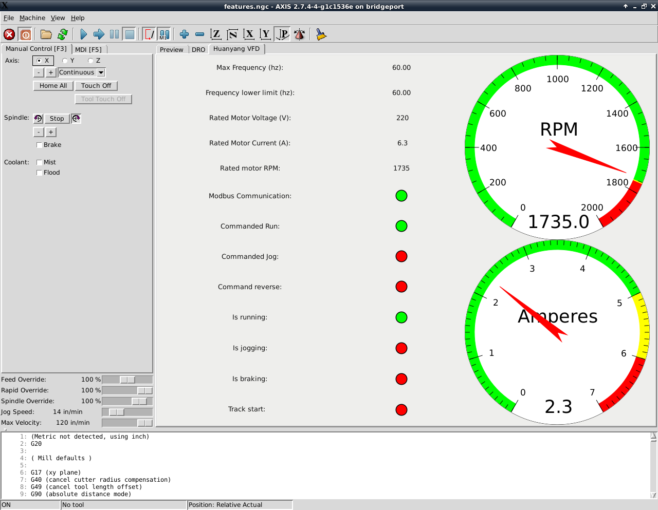
My motor is the same as yours, 1735 designed rpm's. Are you pushing yours over 60hz, if so what limit have you set for it?
EDIT: csbrady, Im guessing you set your spindle RPM's for 1735. Which would make that a 1:1 ratio. Man cant believe I didn't think of that till just now!
Well then... So what is your lower Hz limit and your uppper Hz limit?
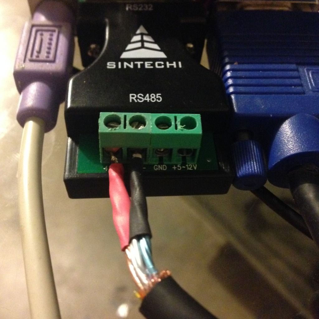
Also, using an old HDMI cable for MODBUS - awesomeness!
Hey! Thanks for the response, I know you have to be scratching you head on my approach. The reason I want to do it this way is because:
Not using the VFD speed control reasons:
1) Using the system as it was designed. I also have a working speed setup with the pneumatic speed rotary controlled via 7i77, and manual switches.
2) I do not have to worry about torque curves or limitations associated with our variable system.
3) I do not have to worry about cooling of the motor/over stressing the motor via exceeding 60hz (over or under)
4) With variable speed, I am not at 1:1 ratio, therefore without a spindle encoder, I do not know what my true spindle speed is.
5) Without the true spindle speed it would be difficult to provide the proper feeds/speeds
Using the VFD with modbus speed control Positives:
1) Control with G-Code
2) easier to implement.
3) Just plain ass cool
lolHonestly I would prefer it to be setup where I need to manually move the RPMs to meet my speed/feeds setup, However I may find it is extremely difficult to implement or impossible. So I may just go with speed control via MODBUS. However with the speed implementation I would have to set a scale factor and I would need to figure out the ratios to do so. It can be done of course but, I do like to go about things the hard-way it would seem!
Unless I'm thinking about this all wrong - which Ive been known to do, then perhaps you could explain it to me so I understand? Where do you have your RPMs manually set at? How do you know what spindle speed you are at?
My motor is the same as yours, 1735 designed rpm's. Are you pushing yours over 60hz, if so what limit have you set for it?
EDIT: csbrady, Im guessing you set your spindle RPM's for 1735. Which would make that a 1:1 ratio. Man cant believe I didn't think of that till just now!
Well then... So what is your lower Hz limit and your uppper Hz limit?
Also, using an old HDMI cable for MODBUS - awesomeness!


Last edit: 15 Feb 2016 01:00 by cncnoob1979.
Please Log in or Create an account to join the conversation.
- csbrady
- Offline
- Senior Member
-
Less
More
- Posts: 72
- Thank you received: 10
15 Feb 2016 04:20 - 15 Feb 2016 04:22 #70140
by csbrady
Replied by csbrady on topic Planning - Bridgeport Interact 1 linuxCNC Retrofit
cncnoob, I had many of the same concerns as you. I have been using a VFD on my machine for about 5 years now.
I ran it for a short time as you are proposing with manually setting the speed. I just looked at the gcode to see the suggested speed and manually set the speed accordingly. I either started the spindle manually to set the speed or set the feed rate to zero and adjusted the speed after the program started. It was satisfactory but not great.
I then connected the VFD to the old Heidenhain controller so that it could control the RPM. That was a nice step up. I set the manual speed to 3000 RPM and then scaled the the control voltage accordingly, 10v=3000 rpm and 5v = 1500. If I wanted to adjust the speed a little I used the manual over-ride on the control.
Now the VFD is more completely integrated with the controller and I have an encoder on the spindle. Another nice step up.
As for your concerns:
Torque curves - There is less available torque at lower RPMs but in 5 years this has never been an issue. I understand the theory, but the reality for me at least has not been a problem.
Cooling/Motor Stresses - I have had some concerns about this but again it seems to generally be a non-issue. I never run the motor at more than about 65 Hz. Going much above 60 Hz is probably not a good idea. For lower speeds, less than 30 Hz, certainly could cause some cooling issues, but only if you are running for long periods of time. Running production all day at low RPMs would be a problem. But with hobbyist use the duty cycle will be quite low. I find that 90% or more of my machining is done at 2000 - 2500 RPM, a real comfortable Hz range for the motor. I spent a day doing fly cutting at low RPM and monitored the motor temperature and it barely got warm. The RPM was low with less cooling, but the load was also quite low.
Spindle Speed - The truth is that without an encoder you don't know what the spindle speed is. The mechanical indication is not very accurate. It's easy to scale the frequency to get accurate speed. If the drive ratio is set at 2000 RPM at 60 Hz then 30 Hz would be exactly 1000 RPM. You are likely to have more inaccuracy with the mechanical drive than with the frequency scaling.
For my setup I set the drive ratio for 2500 RPM at 60 Hz and never change it. I decided to set my maximum speed to 2500 rather than the limit of 3000 to not stress the spindle. My CAM SW limits the commanded speed to 2500 RPM. It took a little trial and error the set the FF1 value for the spindle PID controller to get the commanded speed to match the actual, but it was not difficult.
I have contemplated creating a gear change scenario of sorts. With two sets of parameters it would be easy to have two mechanical ratios one optimized for low RPM and one for high. One could limit the VFD frequency range to 30 - 60 Hz (keeps the motor happy) and have two mechanical set-points, 2500 and 1250 RPM. This would provide a range of 625 to 2500 RPM. I may never get to this since what I have is working quite well. If I end up doing a lot of work at low RPM I'll probably create a low RPM profile. Changing the profile would involve re-starting linuxcnc with a different INI file. If you want to do a lot of real low RPM work you could even do a third profile with a range of 300 to 625 RPM. Creating the profiles is easy. Restarting to switch profiles is not very elegant, but would be fine since it would be very infrequent.
Last edit: 15 Feb 2016 04:22 by csbrady.
Please Log in or Create an account to join the conversation.
- cncnoob1979
-
Topic Author
- Offline
- Platinum Member
-
Less
More
- Posts: 403
- Thank you received: 75
15 Feb 2016 05:07 - 15 Feb 2016 05:09 #70142
by cncnoob1979
Replied by cncnoob1979 on topic Planning - Bridgeport Interact 1 linuxCNC Retrofit
csbrady,
Thank you for the in-depth feedback. I really do appreciate it! I have decided to use the VFD to control my setup, mainly to your response. I will also mess around with the vairi drive a bit for lower speed ranges.
I made a quick calculator that should work for all of the 2J Vari speed heads. If you look at it, you just type in the frequency htz rage in the box, all the numbers will populate with the new spindle speed. Its a down and dirty spreadsheet that I calculated the ratio's and used the resultant rpm. The sheet is protected but without a password, prevents typos This is for if you ever need to manipulate the vari drive. Which you wont need, but perhaps someone else like me would.
Its the best I can hope for at the moment without a spindle encoder to get it accurate.
Just remove the txt extension from the file to view.
How did you go about mounting a spindle encoder? Did you use a mag pickup or did you go with an encoder?
Thank you for the in-depth feedback. I really do appreciate it! I have decided to use the VFD to control my setup, mainly to your response. I will also mess around with the vairi drive a bit for lower speed ranges.
I made a quick calculator that should work for all of the 2J Vari speed heads. If you look at it, you just type in the frequency htz rage in the box, all the numbers will populate with the new spindle speed. Its a down and dirty spreadsheet that I calculated the ratio's and used the resultant rpm. The sheet is protected but without a password, prevents typos
This is for if you ever need to manipulate the vari drive. Which you wont need, but perhaps someone else like me would.Its the best I can hope for at the moment without a spindle encoder to get it accurate.
Just remove the txt extension from the file to view.
How did you go about mounting a spindle encoder? Did you use a mag pickup or did you go with an encoder?
Last edit: 15 Feb 2016 05:09 by cncnoob1979.
Please Log in or Create an account to join the conversation.
- csbrady
- Offline
- Senior Member
-
Less
More
- Posts: 72
- Thank you received: 10
15 Feb 2016 05:14 #70143
by csbrady
Replied by csbrady on topic Planning - Bridgeport Interact 1 linuxCNC Retrofit
cncnoob, I am glad that I was able to help. Adding an encoder to the spindle is quite easy. See my post with pictures here:
forum.linuxcnc.org/forum/12-milling/2966...eport-interact-refit
I just copied what was done here:
igor.chudov.com/projects/Bridgeport-Seri.../32-Spindle-Encoder/
The encoder is cheap and it's not difficult to install.
Chris
forum.linuxcnc.org/forum/12-milling/2966...eport-interact-refit
I just copied what was done here:
igor.chudov.com/projects/Bridgeport-Seri.../32-Spindle-Encoder/
The encoder is cheap and it's not difficult to install.
Chris
Please Log in or Create an account to join the conversation.
- cncnoob1979
-
Topic Author
- Offline
- Platinum Member
-
Less
More
- Posts: 403
- Thank you received: 75
21 Feb 2016 19:41 - 21 Feb 2016 20:06 #70454
by cncnoob1979
Replied by cncnoob1979 on topic Planning - Bridgeport Interact 1 linuxCNC Retrofit
Here is a video of me starting a mockup of a control panel. I want to use a touch sensor to drive my controls. It would be more work and more wiring but could be a very nice setup.
What do you guys think? Would this be worth pursuing?
I can see that with a touch surface oily fingers wouldn't be much of a concern. I would use this for everything except an eStop.
What are some drawbacks that I might not have thought of? But you have to admit it's pretty cool feature if it comes out the way I hope.
I'm using a Arduino uno and I would need some more parts ect to implement - but it's very doable
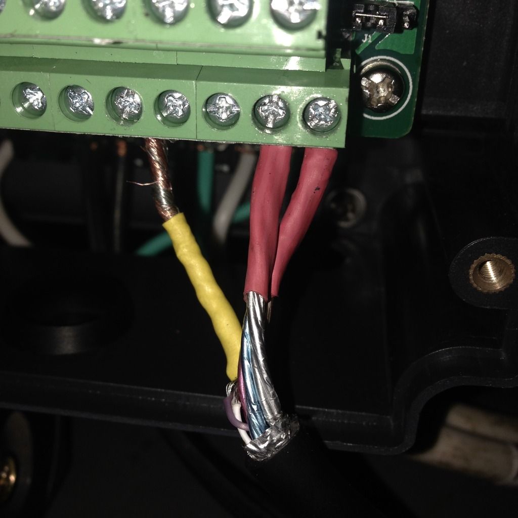
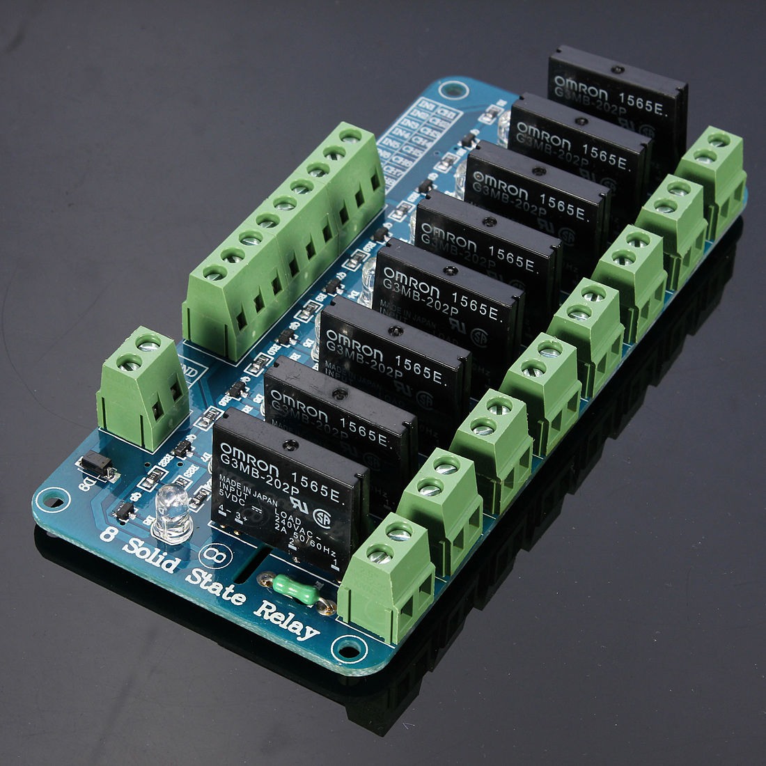
Here are the solid state relays I was speaking of.
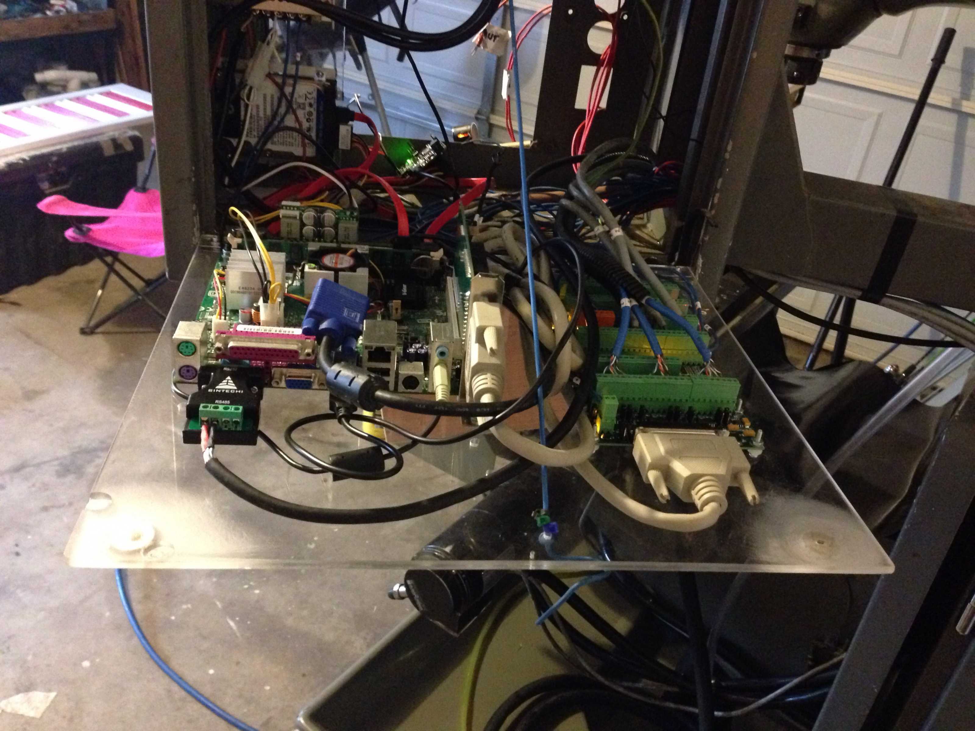
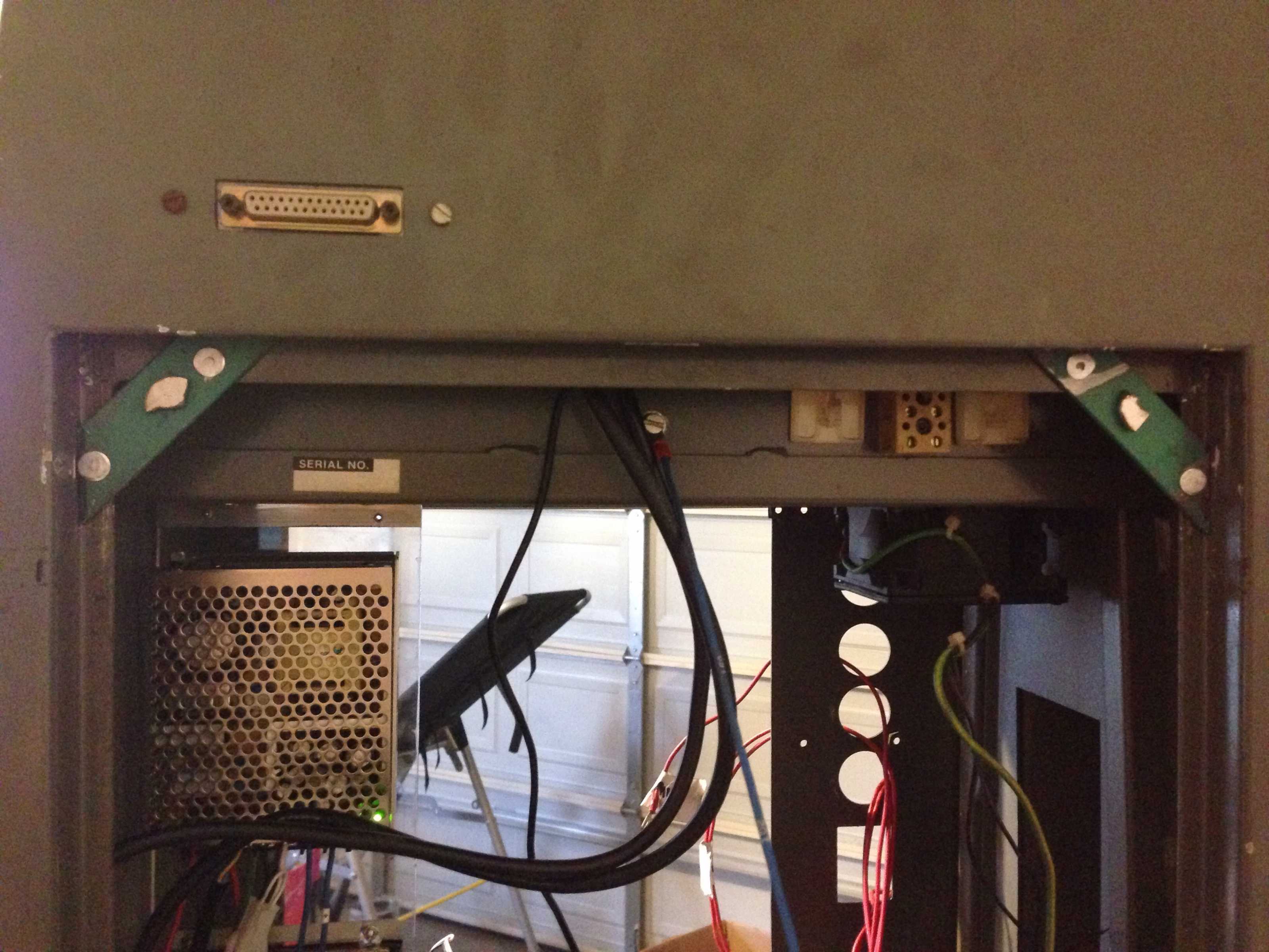
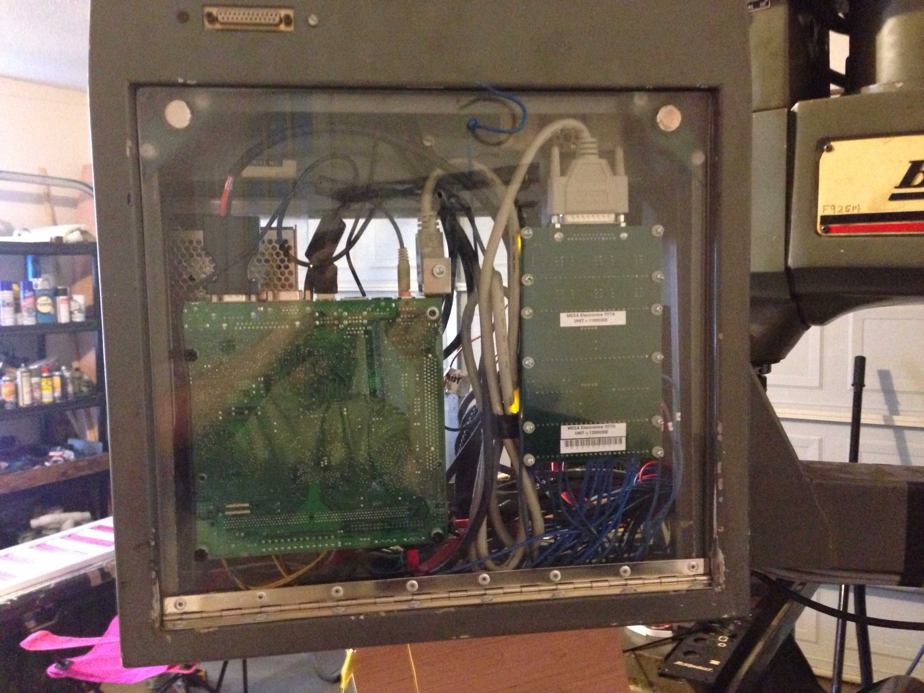
I finally got around to closing the rear enclosure. I'm using strong magnets to hold the upper with as shown in the pictures. I'll get it more refined before long. Still getting a bit done at a time.
But, it is progress!
What do you guys think? Would this be worth pursuing?
I can see that with a touch surface oily fingers wouldn't be much of a concern. I would use this for everything except an eStop.
What are some drawbacks that I might not have thought of? But you have to admit it's pretty cool feature if it comes out the way I hope.
I'm using a Arduino uno and I would need some more parts ect to implement - but it's very doable
Here are the solid state relays I was speaking of.
I finally got around to closing the rear enclosure. I'm using strong magnets to hold the upper with as shown in the pictures. I'll get it more refined before long. Still getting a bit done at a time.
But, it is progress!
Last edit: 21 Feb 2016 20:06 by cncnoob1979.
Please Log in or Create an account to join the conversation.
- csbrady
- Offline
- Senior Member
-
Less
More
- Posts: 72
- Thank you received: 10
22 Feb 2016 03:37 #70464
by csbrady
Replied by csbrady on topic Planning - Bridgeport Interact 1 linuxCNC Retrofit
cncnoob,
My bias would be to use physical switches. When I did my refit I decided that I would use physical switches for all controls that are used to manage machine operation and the touch screen only for setup stuff. I would be a little nervous about using anything but a simple switch for anything that initiates or manages physical motion. I also like having a big buttons that are easy to find with your hand even if you are looking elsewhere, like watching what the machine is doing. I would not use touch switches unless I was very confident that they could never be triggered spuriously.
My bias would be to use physical switches. When I did my refit I decided that I would use physical switches for all controls that are used to manage machine operation and the touch screen only for setup stuff. I would be a little nervous about using anything but a simple switch for anything that initiates or manages physical motion. I also like having a big buttons that are easy to find with your hand even if you are looking elsewhere, like watching what the machine is doing. I would not use touch switches unless I was very confident that they could never be triggered spuriously.
Please Log in or Create an account to join the conversation.
Time to create page: 1.164 seconds