Planning - Bridgeport Interact 1 linuxCNC Retrofit
- cncnoob1979
-
 Topic Author
- Offline
- Platinum Member
-

Less
More
- Posts: 403
- Thank you received: 75
05 Mar 2016 00:36 #71067
by cncnoob1979
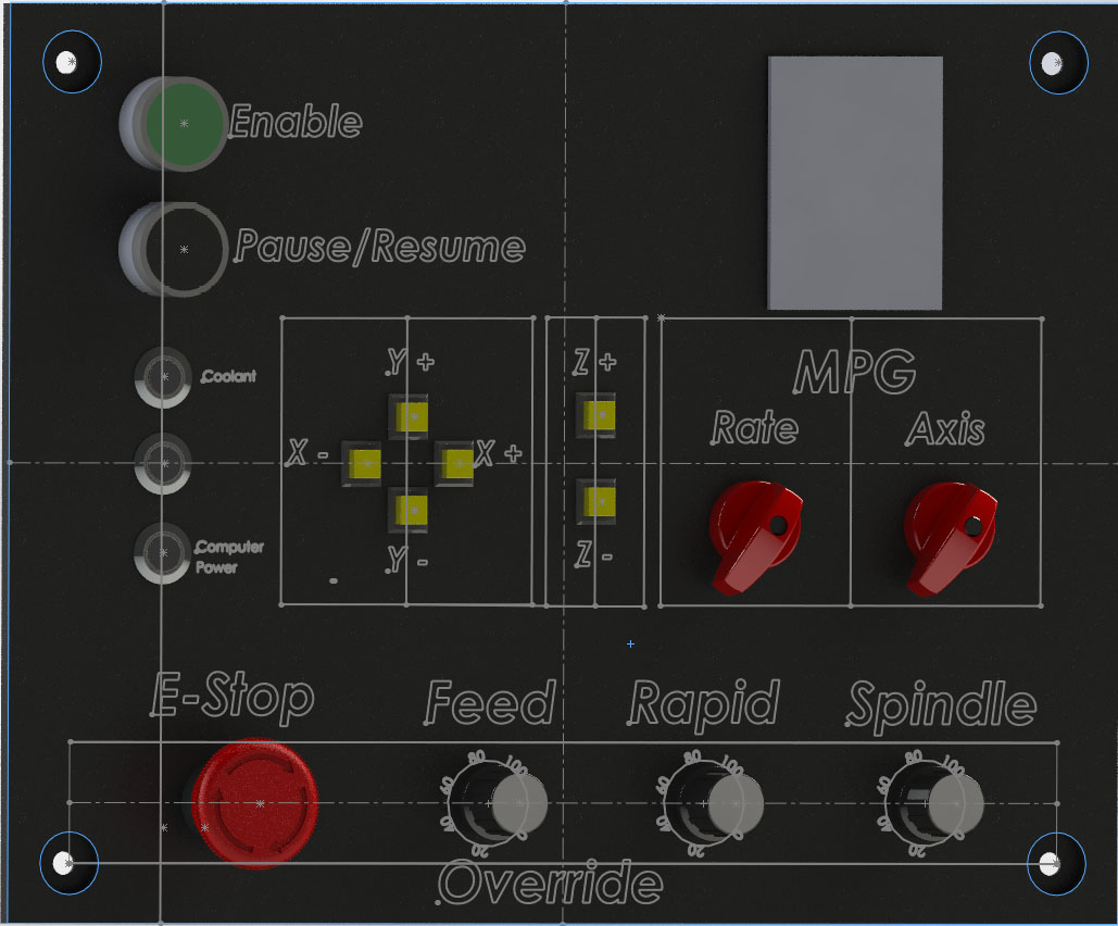
Here is my final render of how I want my panel to look.
csbrady,
I believe I will use my "enable" button for the servo enable. The other will be for start/pause. Do you think this will be sufficient?
Replied by cncnoob1979 on topic Planning - Bridgeport Interact 1 linuxCNC Retrofit
Here is my final render of how I want my panel to look.
csbrady,
I believe I will use my "enable" button for the servo enable. The other will be for start/pause. Do you think this will be sufficient?
Please Log in or Create an account to join the conversation.
- csbrady
- Offline
- Senior Member
-

Less
More
- Posts: 72
- Thank you received: 10
05 Mar 2016 15:16 #71085
by csbrady
Replied by csbrady on topic Planning - Bridgeport Interact 1 linuxCNC Retrofit
I get it now. I thought of the Enable button as a start button. It's a little unusual to have a single start/pause button but it should work well. I have start/step and pause/resume button. So far I have not found the step function useful.
Please Log in or Create an account to join the conversation.
- cncnoob1979
-
Topic Author
- Offline
- Platinum Member
-
Less
More
- Posts: 403
- Thank you received: 75
05 Mar 2016 20:58 - 05 Mar 2016 20:59 #71099
by cncnoob1979
Replied by cncnoob1979 on topic Planning - Bridgeport Interact 1 linuxCNC Retrofit
csbrady,
What size potientiometer did you use? Did you go with 5v 12v or 24v source voltage?
I'm thinking a higher voltage would allow me to scale easier with better noise immunity.
What's your thoughts?
Also with the start / pause button I thought I would use a changed state function. I believe I can do it this way. But I'm not sure how to yet")
Basically on a momentary switch NO:
If high - start
If high state again - pause
// repeat
Or
Which ever state on a latching switch is start and on a change state from high/low pause? Therefore my switch state is irrelevant.
Does that sound feasible?
It maybe easier to just add separate buttons!!
I'm still planning to purchase, I have not bought anything yet. So changes at this time would be easier.
What size potientiometer did you use? Did you go with 5v 12v or 24v source voltage?
I'm thinking a higher voltage would allow me to scale easier with better noise immunity.
What's your thoughts?
Also with the start / pause button I thought I would use a changed state function. I believe I can do it this way. But I'm not sure how to yet
Basically on a momentary switch NO:
If high - start
If high state again - pause
// repeat
Or
Which ever state on a latching switch is start and on a change state from high/low pause? Therefore my switch state is irrelevant.
Does that sound feasible?
It maybe easier to just add separate buttons!!
I'm still planning to purchase, I have not bought anything yet. So changes at this time would be easier.
Last edit: 05 Mar 2016 20:59 by cncnoob1979.
Please Log in or Create an account to join the conversation.
- csbrady
- Offline
- Senior Member
-
Less
More
- Posts: 72
- Thank you received: 10
06 Mar 2016 02:53 #71106
by csbrady
Replied by csbrady on topic Planning - Bridgeport Interact 1 linuxCNC Retrofit
cncnoob,
I used 5K pots with 24v. DigiKey #987-1329-ND. I also got the knobs from DigiKey #226-1022-ND. You will need to do some scaling to get the ranges to work correctly. I had to do some trial and error to get it right. You also will need to scale up the floating point value before converting it to an integer override value or you only get 24 steps. You will save a lot of time if you look at what I did in my hal file.
For the your pause/resume switch you will need to first debounce the input and then use and logic functions to get the desired behavior . Again look at my hal file to get started.
One switch would certainly work, but if you put in two you can copy my hal and might find it more convenient.
Please Log in or Create an account to join the conversation.
- cncnoob1979
-
Topic Author
- Offline
- Platinum Member
-
Less
More
- Posts: 403
- Thank you received: 75
13 Mar 2016 06:20 - 13 Mar 2016 15:10 #71542
by cncnoob1979
Replied by cncnoob1979 on topic Planning - Bridgeport Interact 1 linuxCNC Retrofit
csbrady,
Thanks for the part #'s. You made it very easy for me... so many different possibilities for pot's out there. I received the same pots that you purchased and I have already changed the panel layout a few times.
The buttons that I wanted I could not find for less that 20$ a piece. So I decided to change to cheaper 22mm buttons and try them out. Im sure I will end up changing them sooner or later... its not as clean looking as I would like.
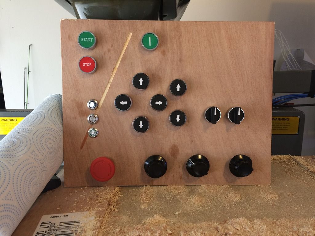
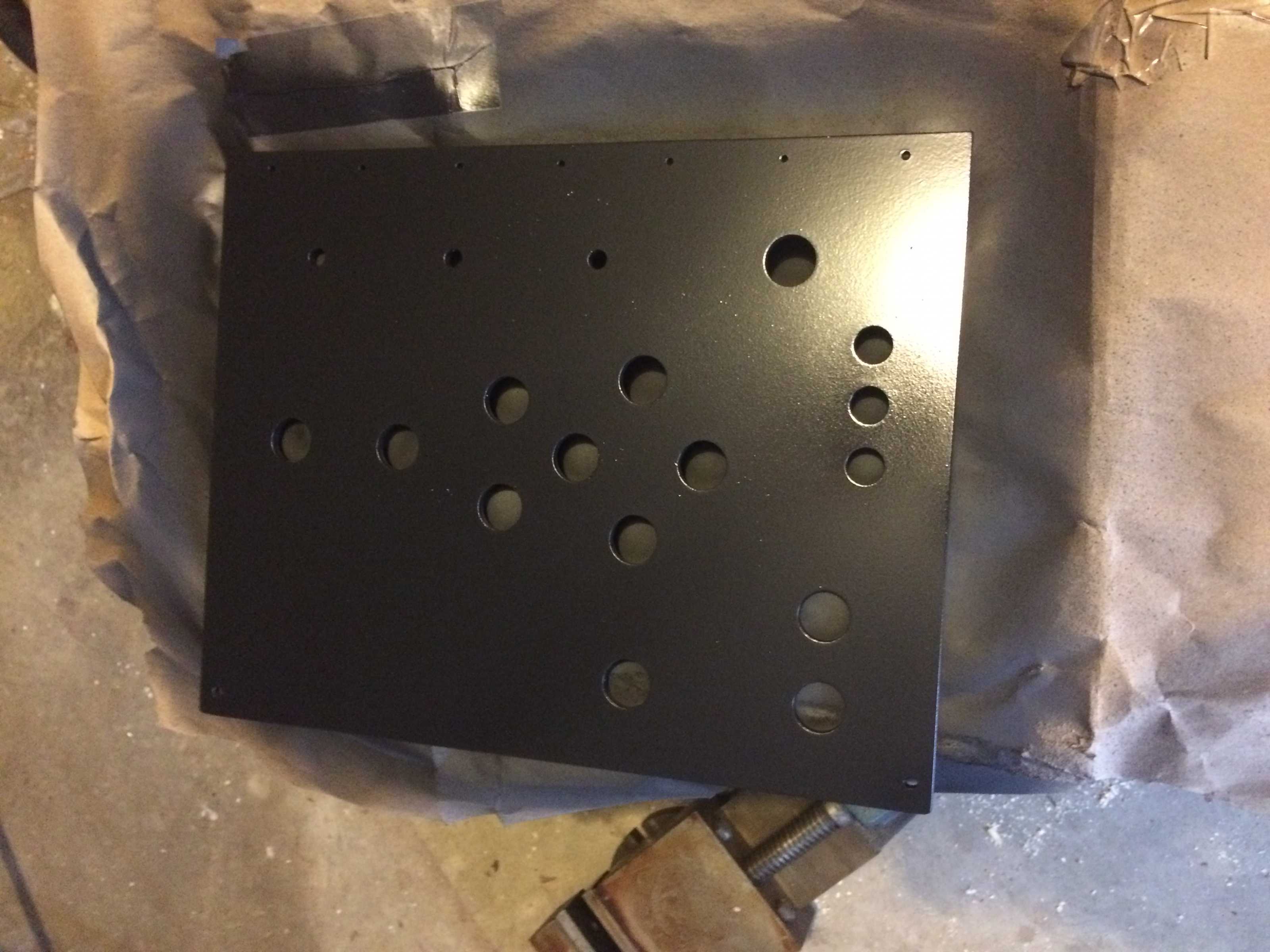
I used the CNC to mill a few panels out of wood looking at the placement and such. I'm glad I did, I did not like how it turned out. I cut the last panel in acrylic .25in. I'll sand and paint this one black to see if I am happy with the results, then perhaps I will engrave it and fill it in with white paint.
I broke my 1/8 and 3/16 end mill from the first plunge with the machine. lol At least now I know that that tool offsets in linuxcnc are overridden by the tool offsets in the CAM program. Plunged straight in at 30 ipm @ 1 1/2 depth... wasn't a purdy site. I had a few hiccups here and there figuring it out. You can see an example on the wooden panel below.
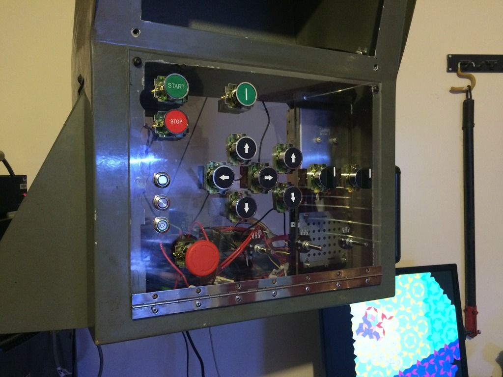
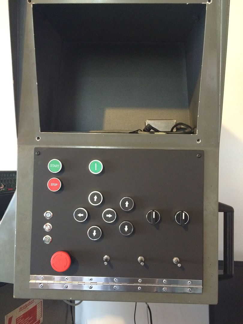
I decided to go with a pinao hinge front panel as well. I raised the hinge using .52 x .25 inch acrylic beneath so the panel can open and close flush. This will allow easier access and also easy to wire together. Tell me what you guys think about it. yeah I know the cheap big buttons aren't that great.
Thanks for the part #'s. You made it very easy for me... so many different possibilities for pot's out there. I received the same pots that you purchased and I have already changed the panel layout a few times.
The buttons that I wanted I could not find for less that 20$ a piece. So I decided to change to cheaper 22mm buttons and try them out. Im sure I will end up changing them sooner or later... its not as clean looking as I would like.
I used the CNC to mill a few panels out of wood looking at the placement and such. I'm glad I did, I did not like how it turned out. I cut the last panel in acrylic .25in. I'll sand and paint this one black to see if I am happy with the results, then perhaps I will engrave it and fill it in with white paint.
I broke my 1/8 and 3/16 end mill from the first plunge with the machine. lol At least now I know that that tool offsets in linuxcnc are overridden by the tool offsets in the CAM program. Plunged straight in at 30 ipm @ 1 1/2 depth... wasn't a purdy site. I had a few hiccups here and there figuring it out. You can see an example on the wooden panel below.
I decided to go with a pinao hinge front panel as well. I raised the hinge using .52 x .25 inch acrylic beneath so the panel can open and close flush. This will allow easier access and also easy to wire together. Tell me what you guys think about it. yeah I know the cheap big buttons aren't that great.


Last edit: 13 Mar 2016 15:10 by cncnoob1979.
Please Log in or Create an account to join the conversation.
- andypugh
-

- Offline
- Moderator
-

Less
More
- Posts: 19875
- Thank you received: 4642
13 Mar 2016 19:51 #71580
by andypugh
Replied by andypugh on topic Planning - Bridgeport Interact 1 linuxCNC Retrofit
One tip for buttons, search eBay for "MAME"
It's an arcade machine emulator, and arcade machine builders need tough buttons.
It's an arcade machine emulator, and arcade machine builders need tough buttons.
Please Log in or Create an account to join the conversation.
- andypugh
-
- Offline
- Moderator
-
Less
More
- Posts: 19875
- Thank you received: 4642
13 Mar 2016 19:53 #71581
by andypugh
Replied by andypugh on topic Planning - Bridgeport Interact 1 linuxCNC Retrofit
Painting and engraving transparent material from the back side could look pretty good, and would be super hard-wearing.
Please Log in or Create an account to join the conversation.
- cncnoob1979
-
Topic Author
- Offline
- Platinum Member
-
Less
More
- Posts: 403
- Thank you received: 75
14 Mar 2016 03:19 - 14 Mar 2016 03:22 #71600
by cncnoob1979
Replied by cncnoob1979 on topic Planning - Bridgeport Interact 1 linuxCNC Retrofit
Andy,
That is an awesome idea. I will definitely do that on the next panel I cut. I read your post too late for me to try it with this panel, but I will use that method for the next.
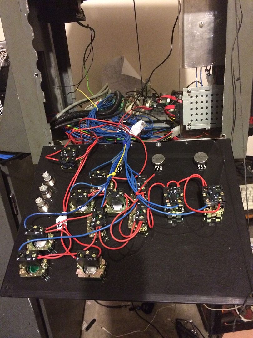
I decided to wire up my panel for now and try to get it going to see what extra buttons I would like or to remove.
I like the idea of using arcade style buttons also. I'm having fun with the project but I really want to get it buttoned up and clean looking.
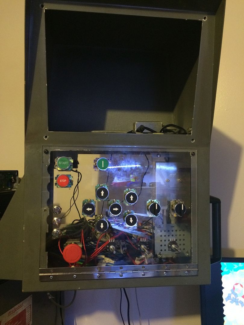
Here is a shot of the panel and wiring so far. I need to buy a quick disconnect plug for the wiring for easy removal sometime.
That is an awesome idea. I will definitely do that on the next panel I cut. I read your post too late for me to try it with this panel, but I will use that method for the next.
I decided to wire up my panel for now and try to get it going to see what extra buttons I would like or to remove.
I like the idea of using arcade style buttons also. I'm having fun with the project but I really want to get it buttoned up and clean looking.
Here is a shot of the panel and wiring so far. I need to buy a quick disconnect plug for the wiring for easy removal sometime.


Last edit: 14 Mar 2016 03:22 by cncnoob1979.
Please Log in or Create an account to join the conversation.
- cncnoob1979
-
Topic Author
- Offline
- Platinum Member
-
Less
More
- Posts: 403
- Thank you received: 75
17 Mar 2016 23:40 - 17 Mar 2016 23:54 #71832
by cncnoob1979
Replied by cncnoob1979 on topic Planning - Bridgeport Interact 1 linuxCNC Retrofit
csbrady,
I have been trying for the past few days to implement your code into my own. I have the start/pause and stop buttons working as expected. However I have not been able to get your code working for jogging. If I go into hal configuration and enable jog axis and set a jog rate it works as expected for the enabled axis.
I have my pot signal (24v at the moment) to 0,1,2 analog inputs on the 7i77 board connected and can see the changes in axis gui with different voltages applied.
Im trying to figure out where you are getting the source signals from. I understand where they are actually physically coming from, but I am not able to pinpoint each out in your code. Its way over my head at the moment.
I looked in the linuxcnc documentation but it seems your code is way more advanced then my little brain can handle. Once functioning correctly I'm sure Ill understand it.
So can I buy you a beer to help me out? I'm sure my configs are all good and messed up by now, sorry for the mess!
EDIT: Perhaps the mystery of your inputs are located in you custom hal file? ....
Here is a piece of the puzzle that I did not use? I assumed it was not for the actual jogging of the machine... now I'm double checking everything again.
I have been trying for the past few days to implement your code into my own. I have the start/pause and stop buttons working as expected. However I have not been able to get your code working for jogging. If I go into hal configuration and enable jog axis and set a jog rate it works as expected for the enabled axis.
I have my pot signal (24v at the moment) to 0,1,2 analog inputs on the 7i77 board connected and can see the changes in axis gui with different voltages applied.
Im trying to figure out where you are getting the source signals from. I understand where they are actually physically coming from, but I am not able to pinpoint each out in your code. Its way over my head at the moment.
I looked in the linuxcnc documentation but it seems your code is way more advanced then my little brain can handle. Once functioning correctly I'm sure Ill understand it.
So can I buy you a beer to help me out?
I'm sure my configs are all good and messed up by now, sorry for the mess!EDIT: Perhaps the mystery of your inputs are located in you custom hal file? ....
###############################################################
# Auto mode output signal, used to gate jog controls
###############################################################
# --- MACHINE-IS-ENABLED ---
net ModeIsManual halui.mode.is-manual => not.1.in
net ModeAuto not.1.out => hm2_5i25.0.7i77.0.0.output-01
Last edit: 17 Mar 2016 23:54 by cncnoob1979.
Please Log in or Create an account to join the conversation.
- cncnoob1979
-
Topic Author
- Offline
- Platinum Member
-
Less
More
- Posts: 403
- Thank you received: 75
17 Mar 2016 23:56 #71833
by cncnoob1979
Replied by cncnoob1979 on topic Planning - Bridgeport Interact 1 linuxCNC Retrofit
csbrady,
Nevermind... I went back into the thread and found your postgui hal file and seen where they are connected. Sorry for any inconvenience, Ill drive right in and connect my switches.
.....
Nevermind... I went back into the thread and found your postgui hal file and seen where they are connected. Sorry for any inconvenience, Ill drive right in and connect my switches.
.....
Please Log in or Create an account to join the conversation.
Time to create page: 0.573 seconds