Planning - Bridgeport Interact 1 linuxCNC Retrofit
- csbrady
- Offline
- Senior Member
-

Less
More
- Posts: 72
- Thank you received: 10
23 Jan 2016 21:25 #69004
by csbrady
Replied by csbrady on topic Planning - Bridgeport Interact 1 linuxCNC Retrofit
Here are my hal and ini files.
Good luck!
Good luck!
Please Log in or Create an account to join the conversation.
- cncnoob1979
-
 Topic Author
- Offline
- Platinum Member
-

Less
More
- Posts: 403
- Thank you received: 75
29 Jan 2016 15:00 - 29 Jan 2016 15:05 #69234
by cncnoob1979
Replied by cncnoob1979 on topic Planning - Bridgeport Interact 1 linuxCNC Retrofit
csbrady,
Thanks for the files! They really help me understand my HAL and INI files.
Here is a video of my spindle running, as well as my mess in the garage. I'm using the cheap 3KW China VFD. I removed the 4MR contactor because one of the contact points fell off! So yeah, it was bad. I tried to remove just the wires and move them to the other contactor. I failed and now I have to trace each wire down again. Anyway...
Just a bit more progress!
Last edit: 29 Jan 2016 15:05 by cncnoob1979.
Please Log in or Create an account to join the conversation.
- cncnoob1979
-
Topic Author
- Offline
- Platinum Member
-
Less
More
- Posts: 403
- Thank you received: 75
30 Jan 2016 04:53 - 30 Jan 2016 05:21 #69260
by cncnoob1979
EDIT: Figured it out, the numbers next to the contactors are locations on the diagram dealing with that system.
I removed my 4MR and now I am having trouble wiring it back up again. I cant seem to get my signal [120v] to enable 5FC. I have ran all the wires but so far no luck. I think I'm just tired and overlooking something simple.
I'm now wishing i would just have left it the way it was. But just removing a relay shouldn't be that bad... yeah right! Good thing I didn't take any pictures to put it back in. [Shot myself in the foot, well.... both feet]
csbrady, If you happen to have some pictures of 4MR, I sure could use them! lol
Replied by cncnoob1979 on topic Planning - Bridgeport Interact 1 linuxCNC Retrofit
EDIT: Figured it out, the numbers next to the contactors are locations on the diagram dealing with that system.
I removed my 4MR and now I am having trouble wiring it back up again. I cant seem to get my signal [120v] to enable 5FC. I have ran all the wires but so far no luck. I think I'm just tired and overlooking something simple.
I'm now wishing i would just have left it the way it was. But just removing a relay shouldn't be that bad... yeah right! Good thing I didn't take any pictures to put it back in. [Shot myself in the foot, well.... both feet]
csbrady, If you happen to have some pictures of 4MR, I sure could use them! lol
Last edit: 30 Jan 2016 05:21 by cncnoob1979.
Please Log in or Create an account to join the conversation.
- csbrady
- Offline
- Senior Member
-
Less
More
- Posts: 72
- Thank you received: 10
09 Feb 2016 03:55 #69817
by csbrady
Replied by csbrady on topic Planning - Bridgeport Interact 1 linuxCNC Retrofit
cncnoob, Did you get the 4MR relay sorted out? I have been away, but can post a picture of the relay or trace wires if you still need it.
Please Log in or Create an account to join the conversation.
- cncnoob1979
-
Topic Author
- Offline
- Platinum Member
-
Less
More
- Posts: 403
- Thank you received: 75
09 Feb 2016 05:12 - 09 Feb 2016 05:17 #69820
by cncnoob1979
Replied by cncnoob1979 on topic Planning - Bridgeport Interact 1 linuxCNC Retrofit
csbrady,
Hey! Thanks but I got it sorted out. I had a floating ground [was a switched ground instead of +24v signal]
I've since made a lot of progress on the mill.
I'm just about ready to start making chips. Now I'm beating my head on the hy_vfd HAL component.
Just figured out how to edit my Hal files/post gui files to get it to load, now I'm not sure if my serial converter to my vfd works. Acts dead, I have it set to the defaults I've read about in the parameters. I have +5v coming from the converter to the VFD's +5v, wired properly imo. Here is the converter I purchased.
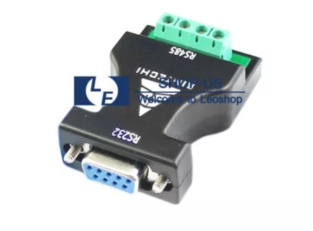
Which vfd did you go with?
Last edit: 09 Feb 2016 05:17 by cncnoob1979.
Please Log in or Create an account to join the conversation.
- andypugh
-

- Offline
- Moderator
-

Less
More
- Posts: 19875
- Thank you received: 4642
09 Feb 2016 11:46 #69833
by andypugh
I have just decided not to bother with Modbus on my system. I have plenty of spare analogue output channels, I will run the VFD that way.
Replied by andypugh on topic Planning - Bridgeport Interact 1 linuxCNC Retrofit
I'm just about ready to start making chips. Now I'm beating my head on the hy_vfd HAL component.
I have just decided not to bother with Modbus on my system. I have plenty of spare analogue output channels, I will run the VFD that way.
Please Log in or Create an account to join the conversation.
- cncnoob1979
-
Topic Author
- Offline
- Platinum Member
-
Less
More
- Posts: 403
- Thank you received: 75
09 Feb 2016 14:26 #69848
by cncnoob1979
Replied by cncnoob1979 on topic Planning - Bridgeport Interact 1 linuxCNC Retrofit
Andy,
Could you give a simple rundown of how you plan to control your VFD without Modbus?
I assume you are going to go 0-10V route? I may go this way depending on if I have a software issue or hardware issue preventing me from getting the hy_vfd component working. Heck, I haven't even confirmed that I have the RS485 chip installed in the VFD!! I am getting +5V from the vfd, So my assumption would be it is installed, but we all now how assumptions are.
Please Log in or Create an account to join the conversation.
- andypugh
-
- Offline
- Moderator
-
Less
More
- Posts: 19875
- Thank you received: 4642
09 Feb 2016 14:39 #69850
by andypugh
Yes, exactly that. I have a bunch of +/-10V outputs spare on the servo driver card, I will use one of those with HAL configured not to output negative voltages. FWD/REV ON/OFF via GPIO. (And an analogue input for current monitoring)
Replied by andypugh on topic Planning - Bridgeport Interact 1 linuxCNC Retrofit
Could you give a simple rundown of how you plan to control your VFD without Modbus?
I assume you are going to go 0-10V route?.
Yes, exactly that. I have a bunch of +/-10V outputs spare on the servo driver card, I will use one of those with HAL configured not to output negative voltages. FWD/REV ON/OFF via GPIO. (And an analogue input for current monitoring)
Please Log in or Create an account to join the conversation.
- csbrady
- Offline
- Senior Member
-
Less
More
- Posts: 72
- Thank you received: 10
09 Feb 2016 15:53 #69855
by csbrady
Replied by csbrady on topic Planning - Bridgeport Interact 1 linuxCNC Retrofit
I started down the path of using modbus for my VFD but decided it would be much simpler to use +10v output and some GPIO lines to manage the VFD.
I suggest adding a couple extra lines to handle fault conditions. It's important to have a VFD fault trigger an estop. I didn't have this for some time and find that cutters that are not rotating do not cut well. The reverse is also a good idea, a signal to stop the VFD when there is a machine estop. I also added line to reset the VFD when an estop is cleared. These 3 signals insure that the machine and spindle are always in sync.
I suggest adding a couple extra lines to handle fault conditions. It's important to have a VFD fault trigger an estop. I didn't have this for some time and find that cutters that are not rotating do not cut well. The reverse is also a good idea, a signal to stop the VFD when there is a machine estop. I also added line to reset the VFD when an estop is cleared. These 3 signals insure that the machine and spindle are always in sync.
Please Log in or Create an account to join the conversation.
- cncnoob1979
-
Topic Author
- Offline
- Platinum Member
-
Less
More
- Posts: 403
- Thank you received: 75
09 Feb 2016 16:31 #69859
by cncnoob1979
Replied by cncnoob1979 on topic Planning - Bridgeport Interact 1 linuxCNC Retrofit
Andy; csbrady,
I'm thinking I will be going the GPIO route as well. Its just frustrating that the MODBUS is not implemented correctly in these VFD's. As I knew beforehand. However, given the fact that I will be manually changing spindle speeds via Vari drive control, I think this will be the best future proof of the spindle setup.
I do have multiple inputs/output pins available. I will have to look through your code csbrady to see how you implemented yours and do the same with mine.
Now I'm off to read Hal and tutorials on how to implement these changes. I'm thinking that to limit the GPIO to only 0-10V will be difficult for me to get my head around. I'm just now -barely- starting to understand how HAL works.
Please Log in or Create an account to join the conversation.
Time to create page: 0.164 seconds