Retrofit cnc 3axis
- clayd_lopunk
- Offline
- Senior Member
-

Less
More
- Posts: 60
- Thank you received: 3
17 Sep 2022 18:38 #252190
by clayd_lopunk
Retrofit cnc 3axis was created by clayd_lopunk
hi guys, i have a cnc machine and i need to figure out how to connect it with linuxcnc. If some electronic expert can tell me how to connect the pins correctly for move machine and wich is the best board of use.in the attached image I should bypass the cables circled in red and send them to linuxcnc with mesa card. Now I don't understand the description of the pin functions. Could it be that the numbers in photo n2 on green correspond to the two serial cables db25 and db9?
Thanks to those who want to help me.
Alex
Thanks to those who want to help me.
Alex
Please Log in or Create an account to join the conversation.
- Aciera
-

- Away
- Administrator
-

Less
More
- Posts: 4740
- Thank you received: 2124
18 Sep 2022 07:55 #252242
by Aciera
Replied by Aciera on topic Retrofit cnc 3axis
If I translate the pin descriptions correctly then the pins you marked green are for the spindle, the limit switches and maybe a toolchanger(?). So as a guess I would say this is a breakout board for digital IO as I don't see anything related to motor drives.
For a retrofit you would generally want to identify the motor and spindle drives first to find out what command interface those use.
Maybe you can provide more information/ photos of the control cabinet.
For a retrofit you would generally want to identify the motor and spindle drives first to find out what command interface those use.
Maybe you can provide more information/ photos of the control cabinet.
Please Log in or Create an account to join the conversation.
- clayd_lopunk
- Offline
- Senior Member
-
Less
More
- Posts: 60
- Thank you received: 3
18 Sep 2022 09:09 #252248
by clayd_lopunk
Replied by clayd_lopunk on topic Retrofit cnc 3axis
The pins in green are my guess but I am small in electronics. I assumed that the numbers in green correspond to the pins of the two 2x62 and 2x63 cables that carry the signals from the PC to the machine in photo(configuration.jpeg). I am attaching the rest of the schematic if you can figure out how I can connect the pins. Theoretically the serial cables db25 and db9 named 2x62 and 2x63 that come out of the cabinet of the machine are the cables on which to make the bridge for linux. The problem is that I can't find the pinout of these. Without knowing what controls the pins I don't know how to connect them and which breakout board to use. In the meantime, thanks for your help
Please Log in or Create an account to join the conversation.
- Aciera
-
- Away
- Administrator
-
Less
More
- Posts: 4740
- Thank you received: 2124
18 Sep 2022 11:58 #252253
by Aciera
Replied by Aciera on topic Retrofit cnc 3axis
6A10, 6A20, 6A30 and 6A40 would be your four motor drives.
Problem is that the internal connecting ribbon cable (in the photo visible going from 5A00 to 6A00) is not shown in the schematics.
I don't think your green pins are directly going to 5X81 / 5X82. Possible that the db25 used to be connected to a parallel port driving step/dir signals for the motors. If that is all the documentation you have then you would either have to reverse engineer some of the circuitry on board 5A00 and 6A00 or replace the electronics. If the motor drives are undocumented as well (they may be from another manufacturer and information may be found on the internet for those separately) then you would likely need to replace those as well. For that you would need more information about the motors though.
Is the PC missing?
Please Log in or Create an account to join the conversation.
- clayd_lopunk
- Offline
- Senior Member
-
Less
More
- Posts: 60
- Thank you received: 3
18 Sep 2022 19:31 - 18 Sep 2022 19:32 #252291
by clayd_lopunk
Replied by clayd_lopunk on topic Retrofit cnc 3axis
The pc is present but the mother software is in dos.
There is no file from which the pin config can be traced.
With reverse engineering, can I go back to the pinout of my two serials?
I have a similar old machine but the pins are written there, maybe by comparing it you can understand how it works. On this, however, there is no db9 pin cable but only the db25. It also does not provide for tool change like this one at present. But the name of cable is the same. I'm attached it
Last edit: 18 Sep 2022 19:32 by clayd_lopunk.
Please Log in or Create an account to join the conversation.
- clayd_lopunk
- Offline
- Senior Member
-
Less
More
- Posts: 60
- Thank you received: 3
18 Sep 2022 19:54 - 18 Sep 2022 19:55 #252294
by clayd_lopunk
Replied by clayd_lopunk on topic Retrofit cnc 3axis
I also found this file of the current machine on the pc, but there is no trace of the pins even if it refers to the pci card that receives the two serial cables of the machine on the pc...

Last edit: 18 Sep 2022 19:55 by clayd_lopunk.
Please Log in or Create an account to join the conversation.
- Aciera
-
- Away
- Administrator
-
Less
More
- Posts: 4740
- Thank you received: 2124
19 Sep 2022 06:37 - 19 Sep 2022 06:44 #252316
by Aciera
Replied by Aciera on topic Retrofit cnc 3axis
From the schematics of the other machine it seems clear that it uses regular step/direction signals for the motor drivers (CKX/DIRX,CKY/DIRY,CKZ/DIRZ,CKW/DIRW)
It's clearly not a simple parallel port though with the 24V.
Not sure how the spindle speed is adjusted. Maybe preset trough REF_1, REF_2, REF_3. That would only give 8 preset speeds though.
Given that all 25 pins are used up on the machine without a toolchanger my guess would be that the db9 cable on the other machine with a toolchanger would be used to carry the signals for the toolchanger itself.
I'd say the chances are pretty high that both machines use the same pinout on the db25. Shouldn't be too hard to get the machine moving with linuxcnc.
To know what board to use we would have to know what signals the toolchanger needs.
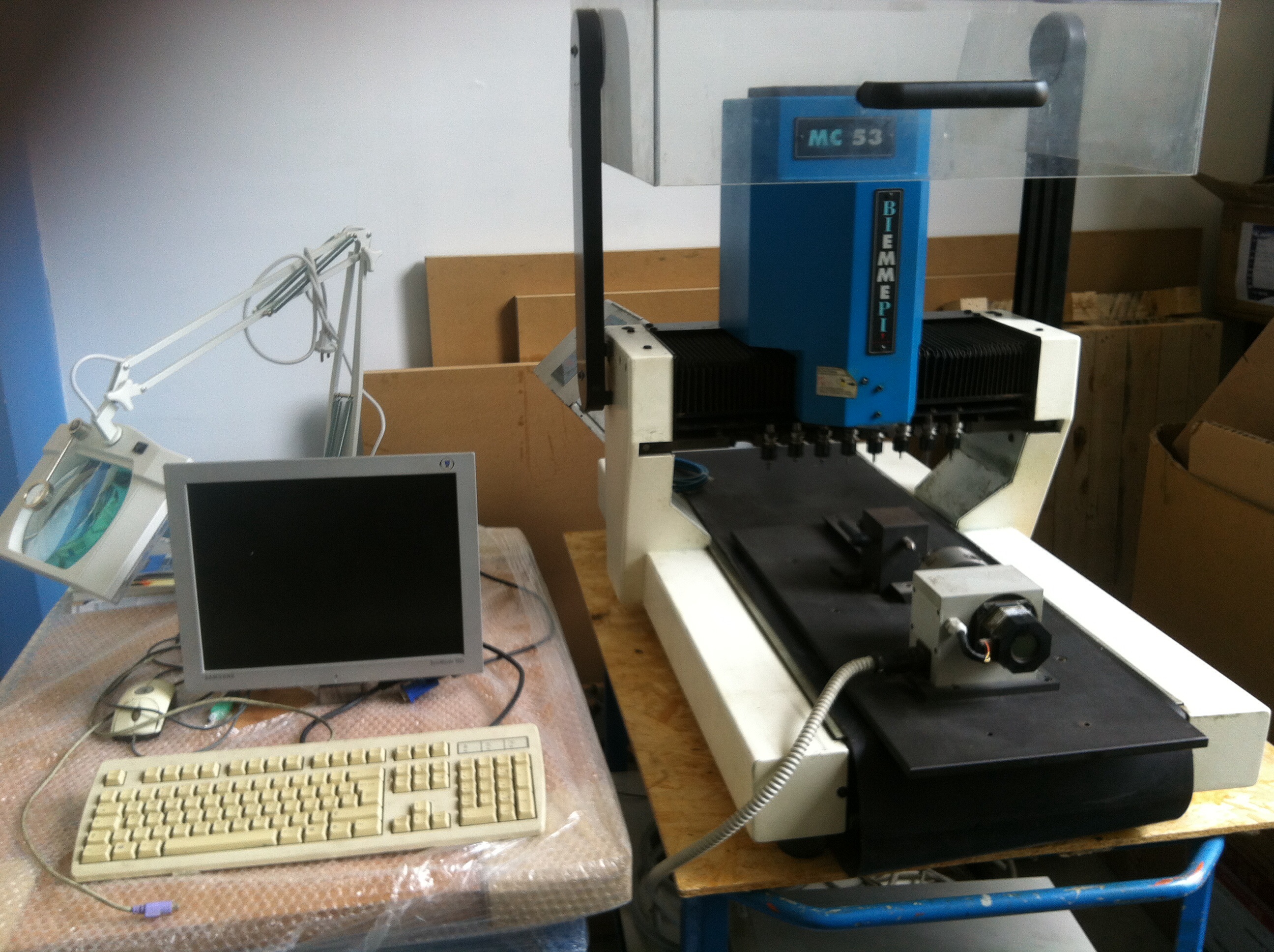
Is this the type of machine we are talking about? :
It's clearly not a simple parallel port though with the 24V.
Not sure how the spindle speed is adjusted. Maybe preset trough REF_1, REF_2, REF_3. That would only give 8 preset speeds though.
Given that all 25 pins are used up on the machine without a toolchanger my guess would be that the db9 cable on the other machine with a toolchanger would be used to carry the signals for the toolchanger itself.
I'd say the chances are pretty high that both machines use the same pinout on the db25. Shouldn't be too hard to get the machine moving with linuxcnc.
To know what board to use we would have to know what signals the toolchanger needs.
Is this the type of machine we are talking about? :
Attachments:
Last edit: 19 Sep 2022 06:44 by Aciera. Reason: typos
The following user(s) said Thank You: tommylight
Please Log in or Create an account to join the conversation.
- clayd_lopunk
- Offline
- Senior Member
-
Less
More
- Posts: 60
- Thank you received: 3
19 Sep 2022 10:57 #252331
by clayd_lopunk
Replied by clayd_lopunk on topic Retrofit cnc 3axis
The machine you linked is the same. Tool change is managed by commands in blue on photo. The magazine of tools opens forward in the X + direction in front of table work, while the cylinder of spindle(mandrino) has gone to the maximum stroke z. Then theoretically each tool has its own distance y at a regular pitch, the spindle moves down in z until it engages the tool, and the magazine close. After the spindle starts.
Connected the db 25 hoping it is the same, can I go for exclusion regarding the pins of the db9? How can I find the ground of the db9? Can I take the electric current in these operations or damage the electrical components by incorrectly connecting the pins?

If I use socket in photo. I connect the cables that come out of the machine on a femaledb25 then I send the wires to a maledb25 that I connect to the breakout board? Same thing for the db9, and I can change the pins without soldering every time right?
thank you very much really for your help!
Connected the db 25 hoping it is the same, can I go for exclusion regarding the pins of the db9? How can I find the ground of the db9? Can I take the electric current in these operations or damage the electrical components by incorrectly connecting the pins?
If I use socket in photo. I connect the cables that come out of the machine on a femaledb25 then I send the wires to a maledb25 that I connect to the breakout board? Same thing for the db9, and I can change the pins without soldering every time right?
thank you very much really for your help!
Please Log in or Create an account to join the conversation.
- Aciera
-
- Away
- Administrator
-
Less
More
- Posts: 4740
- Thank you received: 2124
19 Sep 2022 12:20 #252338
by Aciera
Replied by Aciera on topic Retrofit cnc 3axis
That connector board you posted would certainly make things easier to figure out.
I would presume that the 24V (signal 3.2) is supplied from the "Inverter Mandrino" 3A30. So if our assumption is correct and the 25pin connectors have the same pinout on both machines you should be able to measure +24V between pins 25 and 13.
Then I would use an ohmmeter to check if any of the pins on the db9 connector are connected directly to pin 1 "GND 0V" on connector 5X11 on board 5A00 (switch the multimeter leads around and make sure its low resistance both ways). If you find such a pin on db9 then that would likely be your Ground pin.
You would then want to find out what the voltages of the digital signals are. You might have to measure that with the pc connected and the machine turned on. Measure the DIR and ENABLE pins to GROUND and see if those are 5V or 24V signals.
Use the same approach to find the signals on the db9 connector.
Generally I would start out measuring what voltages you get on the pins that will give you a clearer understanding of how to connect things later to the replacement board.
Shouldn't be to dangerous as long as you stay away from the mains connections (230V) but you wouldn't want to short things out on the connectors if you can avoid it.
Good luck.
Please Log in or Create an account to join the conversation.
- clayd_lopunk
- Offline
- Senior Member
-
Less
More
- Posts: 60
- Thank you received: 3
19 Sep 2022 21:07 #252368
by clayd_lopunk
Replied by clayd_lopunk on topic Retrofit cnc 3axis
Very well, I have a tester of my brother and he knows a minimum of electrical wires, he will help me. So I check the pins if they are 24 volts and see if they coincide with the assumed 25 db pinout.
After I check if the db9 cable is connected to the 5x11 directly and I see the voltage with a tester. In this case if it is a GROUND pin do I have 24 or 5 volts? Otherwise fails to measure? Then the DIR ENABLE AND GROUND pins where are they? Excuse the thousand questions but I know very little about electronics, I do better in information technology..
After I check if the db9 cable is connected to the 5x11 directly and I see the voltage with a tester. In this case if it is a GROUND pin do I have 24 or 5 volts? Otherwise fails to measure? Then the DIR ENABLE AND GROUND pins where are they? Excuse the thousand questions but I know very little about electronics, I do better in information technology..
Please Log in or Create an account to join the conversation.
Time to create page: 0.268 seconds