Retrofit cnc 3axis
- Aciera
-

- Offline
- Administrator
-

Less
More
- Posts: 4698
- Thank you received: 2101
03 Oct 2022 08:59 #253326
by Aciera
Replied by Aciera on topic Retrofit cnc 3axis
On the "output" connector you could connect the ground lead to the bottom leg of one of the transistors (those that are all connected to the pins 2+12.
You can probe the signal on the front or the back, whatever is easier for you.
You can probe the signal on the front or the back, whatever is easier for you.
Please Log in or Create an account to join the conversation.
- clayd_lopunk
- Offline
- Senior Member
-

Less
More
- Posts: 60
- Thank you received: 3
03 Oct 2022 09:10 #253327
by clayd_lopunk
Replied by clayd_lopunk on topic Retrofit cnc 3axis
Incredible Aciera, I had drawn the pins of the flat idc40 seems to match your scheme. You are a devil of electronics !! xD
I am attaching it, and I will proceed to the tests with the card connected, first on the IDC 20 PIN.
So one end on one of the pins 2-11 of the transistors, and the other end on the upper pin of the transistors connected directly to the pin of the IDC 20 and I'm going to probe. First I check my ground and 5v on the pins you told me.
Great, thanks!!
Please Log in or Create an account to join the conversation.
- Aciera
-
- Offline
- Administrator
-
Less
More
- Posts: 4698
- Thank you received: 2101
03 Oct 2022 09:35 - 03 Oct 2022 09:54 #253330
by Aciera
Replied by Aciera on topic Retrofit cnc 3axis
Glad to hear you are making progress.
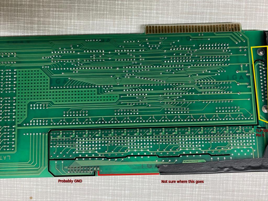
Just out of curiosity, is there actually a DB25pin connector on the other side of the yellow box in the attached image?
It seems there used to be one but I cannot see it on the other side of the board.
edit:
I wonder if that is the elusive DB25 connector from the schematics.
edit2:
Actually, looking at the schematics again I don't think it is.
Attachments:
Last edit: 03 Oct 2022 09:54 by Aciera.
Please Log in or Create an account to join the conversation.
- clayd_lopunk
- Offline
- Senior Member
-
Less
More
- Posts: 60
- Thank you received: 3
03 Oct 2022 11:11 #253334
by clayd_lopunk
Replied by clayd_lopunk on topic Retrofit cnc 3axis
Photo
Please Log in or Create an account to join the conversation.
- clayd_lopunk
- Offline
- Senior Member
-
Less
More
- Posts: 60
- Thank you received: 3
03 Oct 2022 11:12 #253335
by clayd_lopunk
Replied by clayd_lopunk on topic Retrofit cnc 3axis
Yes, I'm happy too, thanks again guys, start having fun playing the little surgeon with my new DVM !! I am sending you a precise photo, the connector above is not there but the pins are there. Perhaps it was used as an interconnect instead of the new card with ISA attachments.
However, I must have confused with the diagrams, one corresponds to the previous model, but the DIR CK pins were described .. in mine, however, no, probably because the signals were managed by the processor card before they reached the cable.
However, I must have confused with the diagrams, one corresponds to the previous model, but the DIR CK pins were described .. in mine, however, no, probably because the signals were managed by the processor card before they reached the cable.
Please Log in or Create an account to join the conversation.
- clayd_lopunk
- Offline
- Senior Member
-
Less
More
- Posts: 60
- Thank you received: 3
03 Oct 2022 22:02 #253388
by clayd_lopunk
Replied by clayd_lopunk on topic Retrofit cnc 3axis
Output
Please Log in or Create an account to join the conversation.
- clayd_lopunk
- Offline
- Senior Member
-
Less
More
- Posts: 60
- Thank you received: 3
03 Oct 2022 22:23 #253390
by clayd_lopunk
Replied by clayd_lopunk on topic Retrofit cnc 3axis
I took the tests. Finally the pins react as assumed. Pin 1-11 with cable disconnected gives me no result. Connecting the flat, I measured all the transistors, the two left groups seem to go to 12V fixed during the enabling of the axes. The groups on the right correspond to DIR STEP of "xyz" and I assume "w" which gives no variation in V. Also pins 2-11 are shared to groups of 4 transistors from what I have detected.
Where I put the H the value is active high and goes from 0 to 12V (although it gets to a slightly lower value lower)
For the central transistors, on the other hand, the value goes to zero if the jogging is negative on the axis and goes to 12v if the jogging is positive on the axis.
I have also drawn from the lights I still have to measure the inputs in VOLT, I am attaching a photo of the latter too. When I press the emergency stop all inputs are turned off. For the rest, I found almost all of the push-button panel, only the spindle potentiometer is missing. I have not found any traces of the latter, neither with the machine being worked, nor in manual control with active spindle. Neither on output devices.
Tomorrow I will measure the V values of the inputs as well. How can I find the spindle and nebulizer? It appears that the input lights are not connected to them.
A big thanks
Please Log in or Create an account to join the conversation.
- clayd_lopunk
- Offline
- Senior Member
-
Less
More
- Posts: 60
- Thank you received: 3
03 Oct 2022 22:27 #253391
by clayd_lopunk
Replied by clayd_lopunk on topic Retrofit cnc 3axis
Input
Please Log in or Create an account to join the conversation.
- Aciera
-
- Offline
- Administrator
-
Less
More
- Posts: 4698
- Thank you received: 2101
04 Oct 2022 06:47 #253416
by Aciera
Replied by Aciera on topic Retrofit cnc 3axis
Don't forget the 8 relay outputs on the 40pin connector. As for the spindle, you would have to follow the cables that connect to the potentiometer on the front panel. My guess is that the potentiometer connects directly to the spindle drive or rather through the pcb that all the drives plug into.How can I find the spindle and nebulizer?
Please Log in or Create an account to join the conversation.
- Aciera
-
- Offline
- Administrator
-
Less
More
- Posts: 4698
- Thank you received: 2101
04 Oct 2022 06:50 - 04 Oct 2022 07:02 #253418
by Aciera
Replied by Aciera on topic Retrofit cnc 3axis
There would still need to be a spindle enable somewhere. Was the machine able to run the spindle in forward and reverse direction?
edit: I would also expect an input for fault signals from the motor drives (not sure how to test that though).
Also it seems a bit odd to me to have 8 outputs to enable the drives maybe some of those pins are for the spindle. If you cannot find more information by testing with the meter you might have to pull the motor drives and the drives pcb from the case and post some pictures or follow the traces from the connectors on that board.
Last edit: 04 Oct 2022 07:02 by Aciera.
Please Log in or Create an account to join the conversation.
Time to create page: 0.120 seconds