Retrofit cnc 3axis
- clayd_lopunk
- Offline
- Senior Member
-

Less
More
- Posts: 60
- Thank you received: 3
02 Oct 2022 10:28 #253240
by clayd_lopunk
Replied by clayd_lopunk on topic Retrofit cnc 3axis
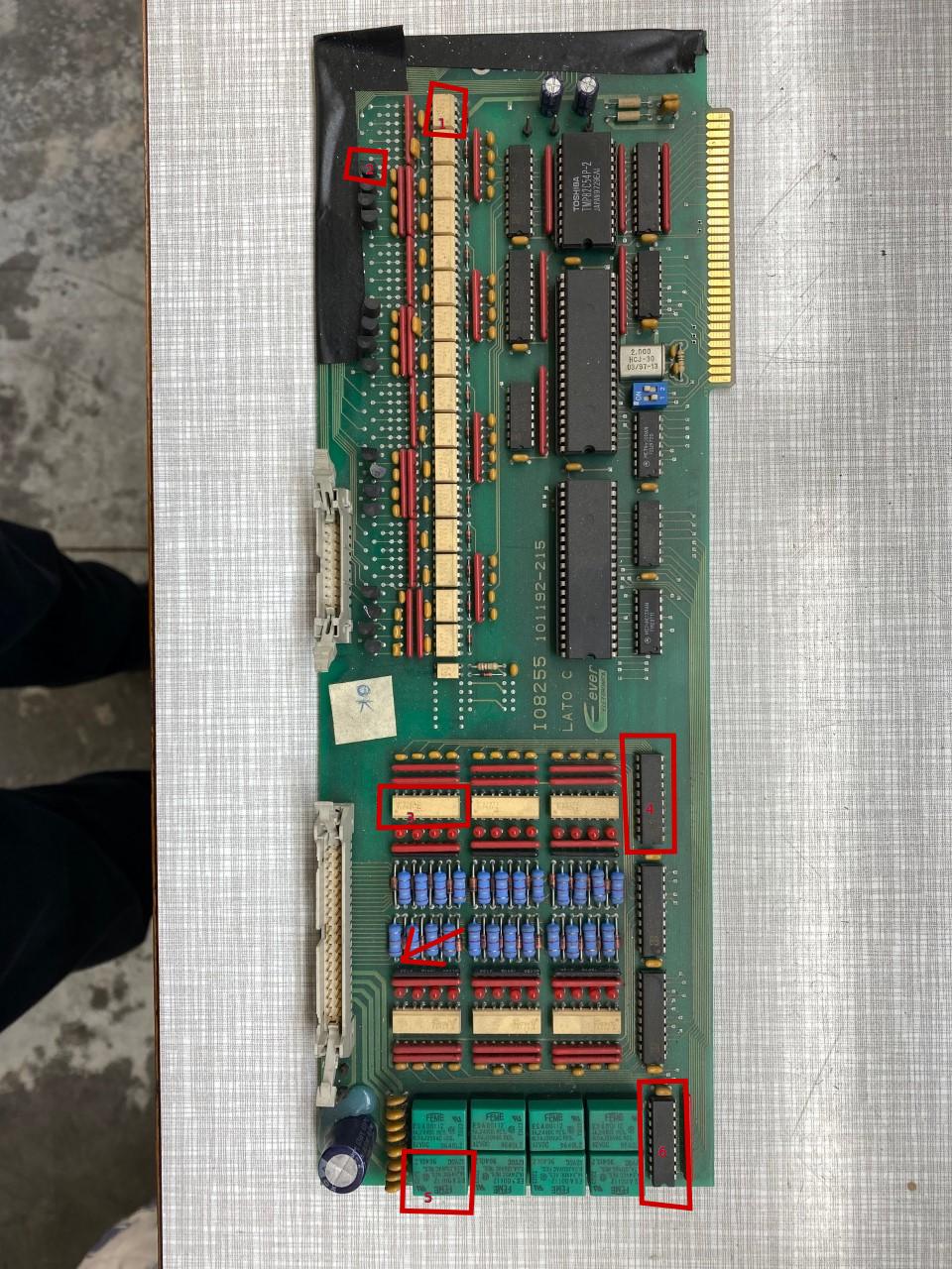
Mythical guys!!! I ran the continuity tests and immediately found the connections. As Aciera claimed, the pins were the upper ones (red), and on the lower pins (yellow) all the transistors share pins 2-12 of the IDC20 flat cable. I have marked the other links. I update the photos of the card. How can I proceed with the inputs? Have i tried circling them in blue, i found their pins but they are few, the cable is IDC40. A good sunday for you!! Thanks
Please Log in or Create an account to join the conversation.
- Aciera
-

- Offline
- Administrator
-

Less
More
- Posts: 4698
- Thank you received: 2101
02 Oct 2022 11:22 #253243
by Aciera
Replied by Aciera on topic Retrofit cnc 3axis
The "input" connector seems carry 6x4= 24 inputs and also 8 relay outputs (the large green blocks on the end of the board). You can see the the 24 thin traces coming out from under the ribbon connector and probably go to one end of one of the large blue resistors (see red arrow on my image). The wider traces will be the going to the relays.
Can you read off the part numbers of the parts marked in red boxes in the attached image or post images with higher resolution that show the part numbers ?I don't need the relay part numbers (marked with number 5 on my image) )those are clear enough on the image.
Can you read off the part numbers of the parts marked in red boxes in the attached image or post images with higher resolution that show the part numbers ?I don't need the relay part numbers (marked with number 5 on my image) )those are clear enough on the image.
Attachments:
Please Log in or Create an account to join the conversation.
- Aciera
-
- Offline
- Administrator
-
Less
More
- Posts: 4698
- Thank you received: 2101
02 Oct 2022 11:32 - 02 Oct 2022 11:42 #253244
by Aciera
Replied by Aciera on topic Retrofit cnc 3axis
Those LEDs (shiny round red parts in 6 groups of four beside the yellow ICs) are going to be very handy to figure out which input is connected to which sensor on the machine. Once you have the pins of the 40pin connector traced to the resistor you will know which pin is active by looking at which LED lights up when running the machine.
edit:
Could you also post a photograph of the back side of that board?
edit:
Could you also post a photograph of the back side of that board?
Last edit: 02 Oct 2022 11:42 by Aciera.
Please Log in or Create an account to join the conversation.
- tommylight
-

- Away
- Moderator
-

Less
More
- Posts: 21606
- Thank you received: 7380
02 Oct 2022 15:36 - 02 Oct 2022 20:41 #253260
by tommylight
Replied by tommylight on topic Retrofit cnc 3axis
I would venture a guess that (6) is an 2003 / 8 darllington transistors that can switch up to 500mA each.
Also a guess, (4) might be multiplexers?
Yellow 8 (1) and 18 (3) pin thingies are optocouplers for sure.
Also a guess, (4) might be multiplexers?
Yellow 8 (1) and 18 (3) pin thingies are optocouplers for sure.
Last edit: 02 Oct 2022 20:41 by tommylight. Reason: typo
Please Log in or Create an account to join the conversation.
- clayd_lopunk
- Offline
- Senior Member
-
Less
More
- Posts: 60
- Thank you received: 3
02 Oct 2022 20:35 #253283
by clayd_lopunk
Replied by clayd_lopunk on topic Retrofit cnc 3axis
Here are updated photos with component codes, n.2 transistors do not have code number.
There are also photos of the back. How can I proceed now?
I have seen that the shipping times of the adapters with clamps (IDC20-MALE AND IDC40-MALE) are long, should I order them in the meantime?
There are also photos of the back. How can I proceed now?
I have seen that the shipping times of the adapters with clamps (IDC20-MALE AND IDC40-MALE) are long, should I order them in the meantime?
Please Log in or Create an account to join the conversation.
- clayd_lopunk
- Offline
- Senior Member
-
Less
More
- Posts: 60
- Thank you received: 3
02 Oct 2022 20:36 #253284
by clayd_lopunk
Replied by clayd_lopunk on topic Retrofit cnc 3axis
some were missing
Please Log in or Create an account to join the conversation.
- scotth
- Away
- Elite Member
-

Less
More
- Posts: 242
- Thank you received: 61
03 Oct 2022 01:44 #253305
by scotth
Replied by scotth on topic Retrofit cnc 3axis
SNx4HC240 Octal Buffers and Line Drivers With 3-State Outputs
The TLP521, TLP521-2 and TLP521-4 series of optically coupled isolator consist of an infrared light emitting diode and an NPN silicon photo transistor in a space efficient Dual In Line Plastic Package.
TOSHIBA Photocoupler IRED & Photo IC
TLP550
Microprocessor System Interfaces
Digital Logic Ground Isolation
Line Receiver
Switching Power Supply Feedback Control
You can find the TLP550 on Ebay.
The following user(s) said Thank You: clayd_lopunk
Please Log in or Create an account to join the conversation.
- Aciera
-
- Offline
- Administrator
-
Less
More
- Posts: 4698
- Thank you received: 2101
03 Oct 2022 07:56 - 03 Oct 2022 08:13 #253320
by Aciera
Replied by Aciera on topic Retrofit cnc 3axis
So for the "Output" side it looks like pins 2+12 are Ground and 1+11 likely +5V (not so sure about this because the traces are hidden by the black tape. Check this with the voltmeter you should measure +5V between Pins1+11 and Pins2+12
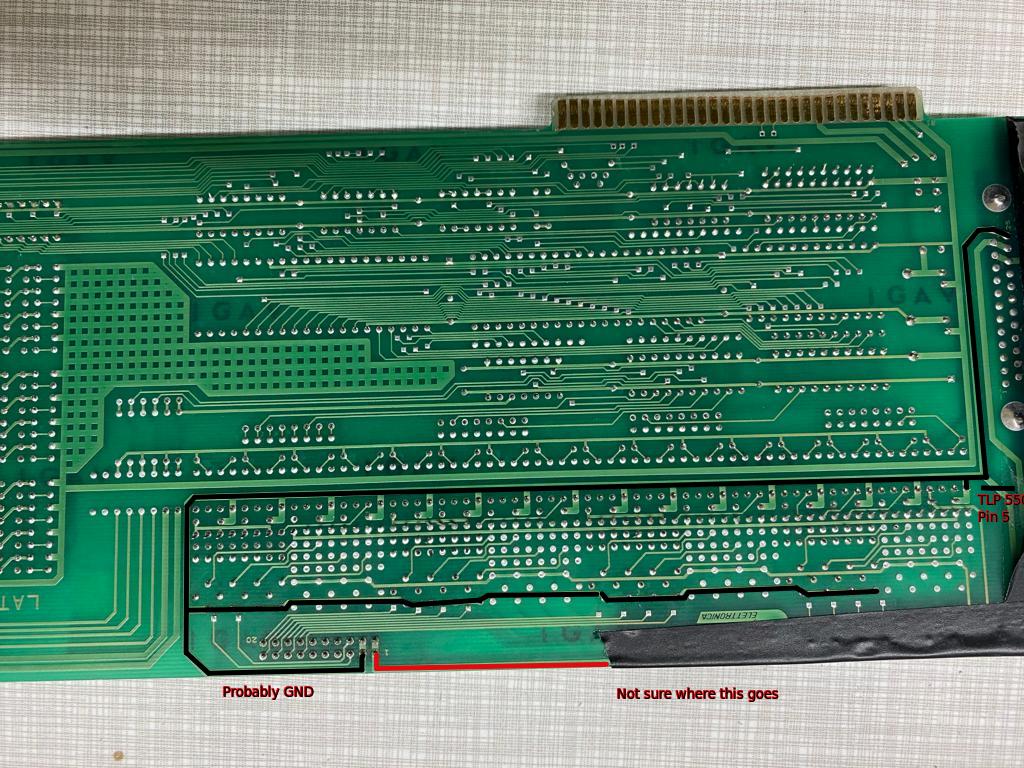
edit: Note that because of all the isolation through the optocouplers you will need to make sure to connect the Ground lead of the voltmeter to the correct Groundpins. (ie the ground for the 20pin "output" connector is not the same as the ground for the 40pin connector.
edit2: This connector would carry all the signals for the motordrives (enable, direction, step), your job now is to find out which pin carries which signal.
edit3:
Yes.I have seen that the shipping times of the adapters with clamps (IDC20-MALE AND IDC40-MALE) are long, should I order them in the meantime?
Attachments:
Last edit: 03 Oct 2022 08:13 by Aciera.
Please Log in or Create an account to join the conversation.
- Aciera
-
- Offline
- Administrator
-
Less
More
- Posts: 4698
- Thank you received: 2101
03 Oct 2022 08:51 #253323
by Aciera
Replied by Aciera on topic Retrofit cnc 3axis
Here my guess for the 40 pin connector:
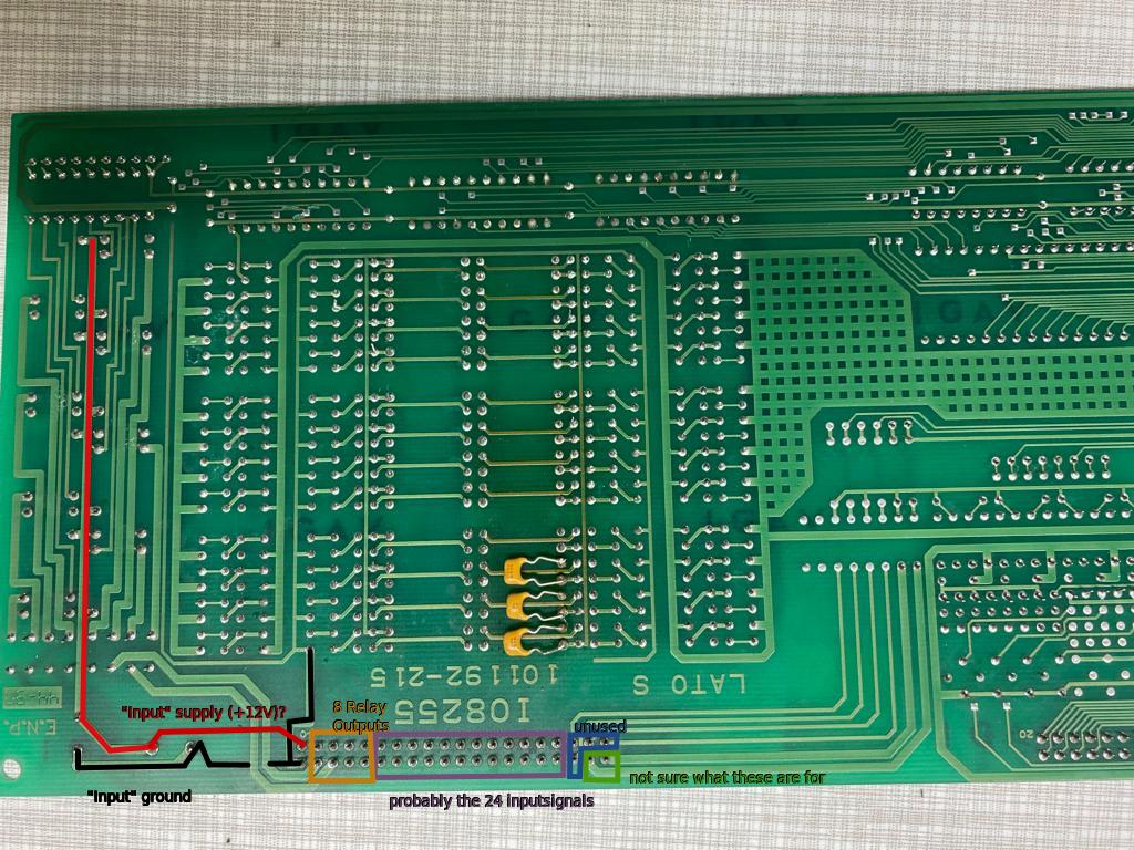
So to check the voltages here you would want to connect the voltmeter to the "input" Ground (there are two pins on the upper side of the board for ground and supply.
Generally I'm not sure where the power is actually coming from.
If you want you can pull out a driver board and post a picture of the front and back so maybe we can figure out more about the driver signals. Other than that I don't think I can provide more information at the moment. Now it's up to you to find which pin on those two connectors is responsible for what function.
Good luck.
Attachments:
Please Log in or Create an account to join the conversation.
- clayd_lopunk
- Offline
- Senior Member
-
Less
More
- Posts: 60
- Thank you received: 3
03 Oct 2022 08:52 #253324
by clayd_lopunk
Replied by clayd_lopunk on topic Retrofit cnc 3axis
Ok Aciera, so now I have to work with the machine connected to the board. I disconnect the flat cable and measure the 5V pins to check if they are correct. Then I connect the cable and find the pins according to the signal. While I jog x, y z ... I can measure the values directly on the transistor pin of the processor card but the ground where I measure it if I have the flat cable attached? Can I measure everything from behind the board, on the IDC20 solder points you marked? Thank you guys!!
Please Log in or Create an account to join the conversation.
Time to create page: 0.156 seconds