Retrofit cnc 3axis
- clayd_lopunk
- Offline
- Senior Member
-

- Posts: 60
- Thank you received: 3
Please Log in or Create an account to join the conversation.
- Aciera
-

- Offline
- Administrator
-

- Posts: 4618
- Thank you received: 2043
Yes (at least if our analysis is correct) The idea is to disconnect the two flat ribbon cables on the processor board:If I want to restore it, I can always do it as long as I reassemble the card, the original PC and connect the right cable?
Then you can remove the pc-motherboard, the processor board and the interconnection board (the one with all the large black connectors). The easiest would be to buy terminal boards for each of the two ribbon connectors (like the ones you got for the db25 but with different connectors) and wire the signals from there to the new breakout board.
Before you do that you would want to find out as much as you can about the pin out of those two ribbon connectors with your DVM.
Attachments:
Please Log in or Create an account to join the conversation.
- tommylight
-

- Away
- Moderator
-

- Posts: 21086
- Thank you received: 7200
Please Log in or Create an account to join the conversation.
- Aciera
-

- Offline
- Administrator
-

- Posts: 4618
- Thank you received: 2043
www.aliexpress.com/item/32799636212.html
Please Log in or Create an account to join the conversation.
- clayd_lopunk
- Offline
- Senior Member
-

- Posts: 60
- Thank you received: 3
Before that to perform the tests on the pins of the flat cables with the DVM do I have to disconnect them from the processor board (white)? And do I already have the IDC adapters for my cables?
Thanks guyss!!
Please Log in or Create an account to join the conversation.
- Aciera
-

- Offline
- Administrator
-

- Posts: 4618
- Thank you received: 2043
You may have to apply a mixed strategy like before on the db25 connector. You can try continuity testing with the power off and voltage measurement with the machine running to find what is happening when different functions are activated. First thing you will want to figure out with the machine off is to find a ground connection to clamp your voltage meter to before you start to measure voltages. I would expect that some pins on those connectors could be traced directly to the drives but if the pins on the drives connectors are not labeled then that might be of limited use.Before that to perform the tests on the pins of the flat cables with the DVM do I have to disconnect them from the processor board (white)?
I don't know, I have not seen any.And do I already have the IDC adapters for my cables?
Please Log in or Create an account to join the conversation.
- clayd_lopunk
- Offline
- Senior Member
-

- Posts: 60
- Thank you received: 3
Please Log in or Create an account to join the conversation.
- Aciera
-

- Offline
- Administrator
-

- Posts: 4618
- Thank you received: 2043
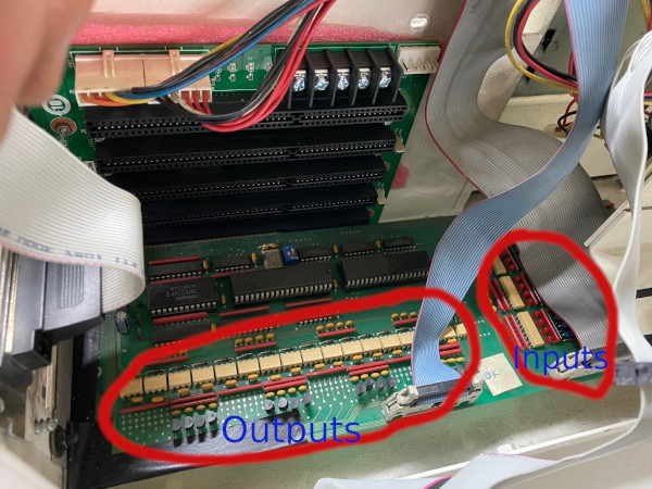
The fact that you have probably 16 outputs and likely just as many inputs make it easier to identify one part on the board that is directly connected to the connector and use that knowledge to find all the other outputs and inputs on the board.
Please Log in or Create an account to join the conversation.
- Aciera
-

- Offline
- Administrator
-

- Posts: 4618
- Thank you received: 2043
The transistors are the little black parts that you see in four groups of four above the connector. Looking at the image of the pcb I would guess it's the the top pins that point away from the connector.
For the input side we would need a better image with the flat ribbon cable removed to reveal what is underneath.
Please Log in or Create an account to join the conversation.
- clayd_lopunk
- Offline
- Senior Member
-

- Posts: 60
- Thank you received: 3
Thanks
Please Log in or Create an account to join the conversation.

