
- Posts: 4819
- Thank you received: 2177
Trajectory Planner using Ruckig Lib
- Aciera
- Offline
- Administrator
-

Less
More
2 years 3 months ago #304600
by Aciera
Replied by Aciera on topic Trajectory Planner using Ruckig Lib
If the clothoid library can only create 2d curves then the only solution I see would be to approximate all arcs with a polyline. Which is exactly what 5axis CAM output seems to do.
With this approach there would only be line-line segment corners.
With this approach there would only be line-line segment corners.
The following user(s) said Thank You: Lcvette, Grotius
Please Log in or Create an account to join the conversation.
- Grotius
- Offline
- Platinum Member
-

Less
More
- Posts: 2419
- Thank you received: 2349
2 years 3 months ago #304612
by Grotius
Replied by Grotius on topic Trajectory Planner using Ruckig Lib
I presume that can be any plane in space (ie it does not have to be XY XZ or YZ)?
Yes, any plane.
If that is correct we can use the plane that is defined by the tool orientation vector and the corresponding point (TA knot) and project the two TA line segments (ie the one that comes from the previous TA knot and the one that goes to the next TA knot) onto that plane. Then we have the projected lines on a common plane and we can use the clothoids library to create a G2 continuous fillet.
Of course we would need to do this for all TA knots and their respective planes in space.
Yes that is correct. Three ta knot's can create a plane. On this plane we could record the tcp-ta intersection along the plane.
Maybe this is the best solution, we have to test it i think.
[edit]
Ok, I think we can forget this idea as this will still not create 3D clothoid curves but only 2D.
[/edit]
It will create a 2d clothoid in 3d space, it's valid as long it draw's the clothoid on a 3d plane with the current clothoid lib as is.
Isn't this the same situation as you would have when adding a fillet between a straight line segment and a helix segment in Gcode (except of course the helix segment would be oriented to XY, XZ or YZ plane)?
For now it isn't valid to create clothoid fillet on a helix. I didn't told it yet. It would be valid if clothoid is 3d.
It would be valid if fillet is of type 3d spline.
How do you handle line-3d_arc segment corners in tool paths?
I think you mean, for using clothoids valid combinations are line-arc, arc-line, arc-arc as long as they are on the same plane.
If the clothoid library can only create 2d curves then the only solution I see would be to approximate all arcs with a polyline. Which is exactly what 5axis CAM output seems to do.
With this approach there would only be line-line segment corners.
The situation we have now is a 3d arc to 3d arc connection, both arc's are on exotic plane position. non xy,xz etc.
So this would not happen in normal gcode. This happens because we have a tooldir path recorded.
For normal gcode, i think the clothoid can cover 95%-100% of the fillets.
Things left to investegate:
1. We can test your plane idea using the 2 ta knots as plane.
2. We can test using 3d spline fillets, for our tooldir path.
3. We can invest more time in creating 3d clothoids to cover all exeptions.
The following user(s) said Thank You: Lcvette, Darium
Please Log in or Create an account to join the conversation.
- Aciera
- Offline
- Administrator
-
Less
More
- Posts: 4819
- Thank you received: 2177
2 years 3 months ago - 2 years 3 months ago #304632
by Aciera
Note, the tool orientation vector and the current TA knot already define a plane:

This crossed my mind as well but will only work for small changes in orientation angles. If we have a simple move like this:
G1 X0 A0
G1 x100 A180
there is no single plane that records the intersection path of the tcp-ta vector. As the vector rotates from pointing straight up to pointing straight down the resulting curve would disappear in infinity.
Replied by Aciera on topic Trajectory Planner using Ruckig Lib
Yes that is correct. Three ta knot's can create a plane.
Note, the tool orientation vector and the current TA knot already define a plane:
On this plane we could record the tcp-ta intersection along the plane.
This crossed my mind as well but will only work for small changes in orientation angles. If we have a simple move like this:
G1 X0 A0
G1 x100 A180
there is no single plane that records the intersection path of the tcp-ta vector. As the vector rotates from pointing straight up to pointing straight down the resulting curve would disappear in infinity.
Last edit: 2 years 3 months ago by Aciera.
The following user(s) said Thank You: Lcvette, Grotius, Darium
Please Log in or Create an account to join the conversation.
- Aciera
- Offline
- Administrator
-
Less
More
- Posts: 4819
- Thank you received: 2177
2 years 3 months ago - 2 years 3 months ago #304639
by Aciera
Replied by Aciera on topic Trajectory Planner using Ruckig Lib
This 2020 publication proposes the use of 3d clothoid fillets for space corner smoothing in tool paths:
www.sciencedirect.com/science/article/abs/pii/S0736584519306222
So it seems that 2D fillets are still the norm in tool path segment blending, which gives me the impression that even modern controllers can't blend non-planar segment corners including anything that involves a helix (which is often used for tool entry moves). I have no idea really but this might explain why 3D CAM toolpaths are often made up of short straight segments as two straight segments will always form a planar corner.
All this makes me think that using the current (planar) clothoid library would require a segmentation of the recorded tool orientation path and then calculate the plane and fillet for every segment corner. I wouldn't know how to do the segmentation of the recorded orientation path much less if this is computationally feasable. Also it seems kind of silly to have to segment an entire helix when it is really just the beginning and the end that need fillets.
I had a look at your proposed method of fitting helixes:
forum.linuxcnc.org/38-general-linuxcnc-q...lib?start=420#303355
This would probably be ok for many cases, however I'm somewhat skeptical about the predictability of the path deviation as it seems to deform the helix not only locally at the beginning and the end but also quite noticeably in the middle. If this was done to our helical path of the tool orientation the deviation of the orientation angle might well be beyond acceptable.
So for the moment I have run out of ideas, unfortunately.
Last edit: 2 years 3 months ago by Aciera. Reason: Add the link to the publication
The following user(s) said Thank You: Lcvette, Grotius
Please Log in or Create an account to join the conversation.
- Grotius
- Offline
- Platinum Member
-
Less
More
- Posts: 2419
- Thank you received: 2349
2 years 3 months ago #304695
by Grotius
Replied by Grotius on topic Trajectory Planner using Ruckig Lib
Hi Arciera,
After investing more time into the 3d clothoids. I wasn't able to get it work like it would be. So now the
green line is a bspline 3-degree. This works ok.
Let we use this bspline for the toolpath fillets.
You see there is a differance in clothoids and or bspline. The clothoids are bigger curves.
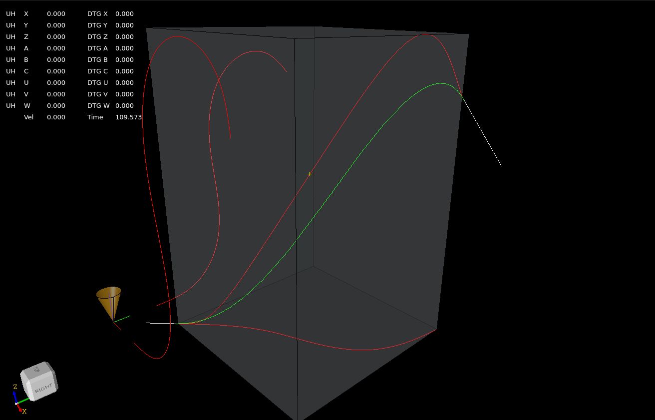
So tomorrow i can integrate the b-spline into the trajectory planner, it needs interpolation function etc.
After investing more time into the 3d clothoids. I wasn't able to get it work like it would be. So now the
green line is a bspline 3-degree. This works ok.
Let we use this bspline for the toolpath fillets.
You see there is a differance in clothoids and or bspline. The clothoids are bigger curves.
So tomorrow i can integrate the b-spline into the trajectory planner, it needs interpolation function etc.
The following user(s) said Thank You: Lcvette, Aciera, Darium
Please Log in or Create an account to join the conversation.
- Grotius
- Offline
- Platinum Member
-
Less
More
- Posts: 2419
- Thank you received: 2349
2 years 3 months ago #304697
by Grotius
Replied by Grotius on topic Trajectory Planner using Ruckig Lib
github.com/krcwrhvgyxzqelljes/hal-core
So it seems that 2D fillets are still the norm in tool path segment blending, which gives me the impression that even modern controllers can't blend non-planar segment corners including anything that involves a helix (which is often used for tool entry moves).
I really have no idea. We now can do 95% of blending using clothoids for normal gcode.
For helix and non-planar stuff like tooldir blending, we can use b-spline blending. I think this is logical as long
as the Italian mathmeticians have not provided us the 3d clothoid algo. hihi.
as two straight segments will always form a planar corner.
Yes this makes it easyer to create a plane from 3 input points and perform fillet operations on that plane.
Also it seems kind of silly to have to segment an entire helix when it is really just the beginning and the end that need fillets.
Yes i agree. Just let it be an arc with a z value.
Note, the tool orientation vector and the current TA knot already define a plane:
Yes.
This crossed my mind as well but will only work for small changes in orientation angles. If we have a simple move like this:
G1 X0 A0
G1 x100 A180
To blend this spiral move, we use the b-spline at the X0 and the previous attached curve's end.
Ok i think i have a lot to do tommorrow, i think without wasting a lot off time in investegating as now we know what to do.
The following user(s) said Thank You: Lcvette, Aciera
Please Log in or Create an account to join the conversation.
Time to create page: 2.111 seconds