scurve trajectory planner
- juliankoenig87
- Offline
- Premium Member
-

Less
More
- Posts: 119
- Thank you received: 55
21 Jan 2025 21:30 #319593
by juliankoenig87
Replied by juliankoenig87 on topic scurve trajectory planner
Thank you for your answer.
I now understand every parameter and tested a little.
One thing I don't like. A given gcode with G64 P0.1 (mm) with an 90 degree edge. The small line upwards is 0.1 mm right of the edge. Your scurve tp sets a radius of 0.1 mm and the default tp sets a radius so that the distance between the blended path and the original path is not greater then 0.1 mm. I always set with a P value the maximum allowed deviation of a given path. So now I am not really sure. Can I just calculate something?
Please Log in or Create an account to join the conversation.
- ihavenofish
- Offline
- Platinum Member
-

Less
More
- Posts: 1013
- Thank you received: 285
22 Jan 2025 04:15 - 22 Jan 2025 04:16 #319617
by ihavenofish
Ah, that's not ideal. P needs to be a tolerance, definitely not a radius cause you end up up needing to pick a super tiny radius which entirely negated the point of G64.
Replied by ihavenofish on topic scurve trajectory planner
Thank you for your answer.
I now understand every parameter and tested a little.
One thing I don't like. A given gcode with G64 P0.1 (mm) with an 90 degree edge. The small line upwards is 0.1 mm right of the edge. Your scurve tp sets a radius of 0.1 mm and the default tp sets a radius so that the distance between the blended path and the original path is not greater then 0.1 mm. I always set with a P value the maximum allowed deviation of a given path. So now I am not really sure. Can I just calculate something?
Ah, that's not ideal. P needs to be a tolerance, definitely not a radius cause you end up up needing to pick a super tiny radius which entirely negated the point of G64.
Last edit: 22 Jan 2025 04:16 by ihavenofish.
Please Log in or Create an account to join the conversation.
- Aciera
-

- Offline
- Administrator
-

Less
More
- Posts: 4724
- Thank you received: 2117
22 Jan 2025 11:05 - 22 Jan 2025 13:20 #319625
by Aciera
Replied by Aciera on topic scurve trajectory planner
Yes, the problem with using a fixed blend radius on all segment intersections would be that the path deviation depended on the angle at which the two segments intersect, which would be rather unfortunate (If that is indeed what it is doing). For angles larger than 60° the blend radius and thus the feed rate could actually be larger for a 0.1mm deviation while angles below 60° would require a smaller blend radius to stay within a maximum deviation of 0.1mm.
Last edit: 22 Jan 2025 13:20 by Aciera.
Please Log in or Create an account to join the conversation.
- juliankoenig87
- Offline
- Premium Member
-
Less
More
- Posts: 119
- Thank you received: 55
22 Jan 2025 11:15 #319627
by juliankoenig87
Replied by juliankoenig87 on topic scurve trajectory planner
Ok. As long as I am aware of it I can handle with it and I will choose smaller values.
Right now I am trying to get a 4 axis Machine running. Right now the scurve tp is making a lot dump things.
Grotius, do you have a 4 axis sim machine running to play with?
Right now I am trying to get a 4 axis Machine running. Right now the scurve tp is making a lot dump things.
Grotius, do you have a 4 axis sim machine running to play with?
The following user(s) said Thank You: Darium
Please Log in or Create an account to join the conversation.
- hmnijp
- Offline
- Senior Member
-

Less
More
- Posts: 42
- Thank you received: 49
22 Jan 2025 15:11 - 23 Jan 2025 09:47 #319640
by hmnijp
I am also concerned about the compression algorithm that creates polygons if you increase the ‘P’ value. I have prepared a comparison with the old path planner:
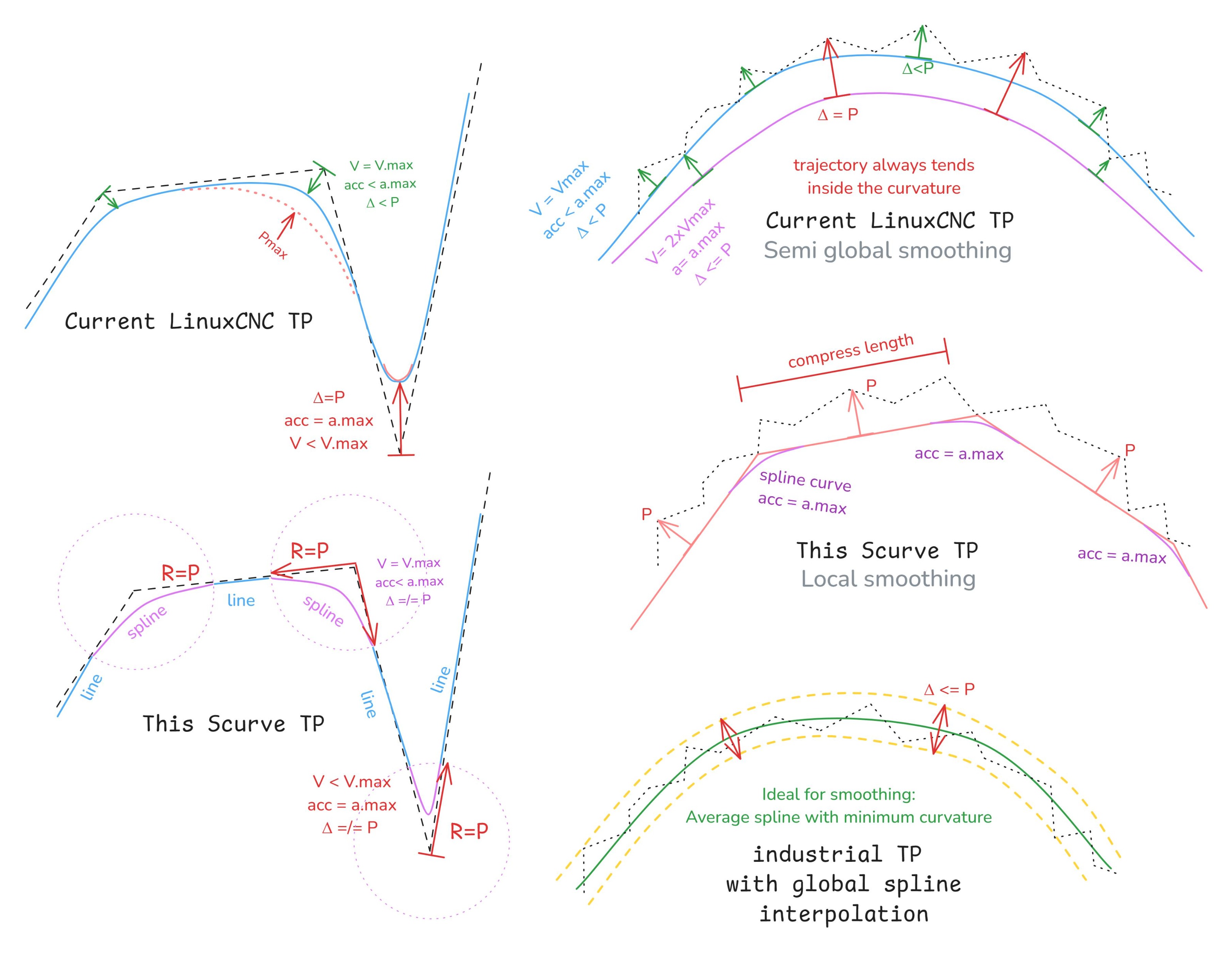
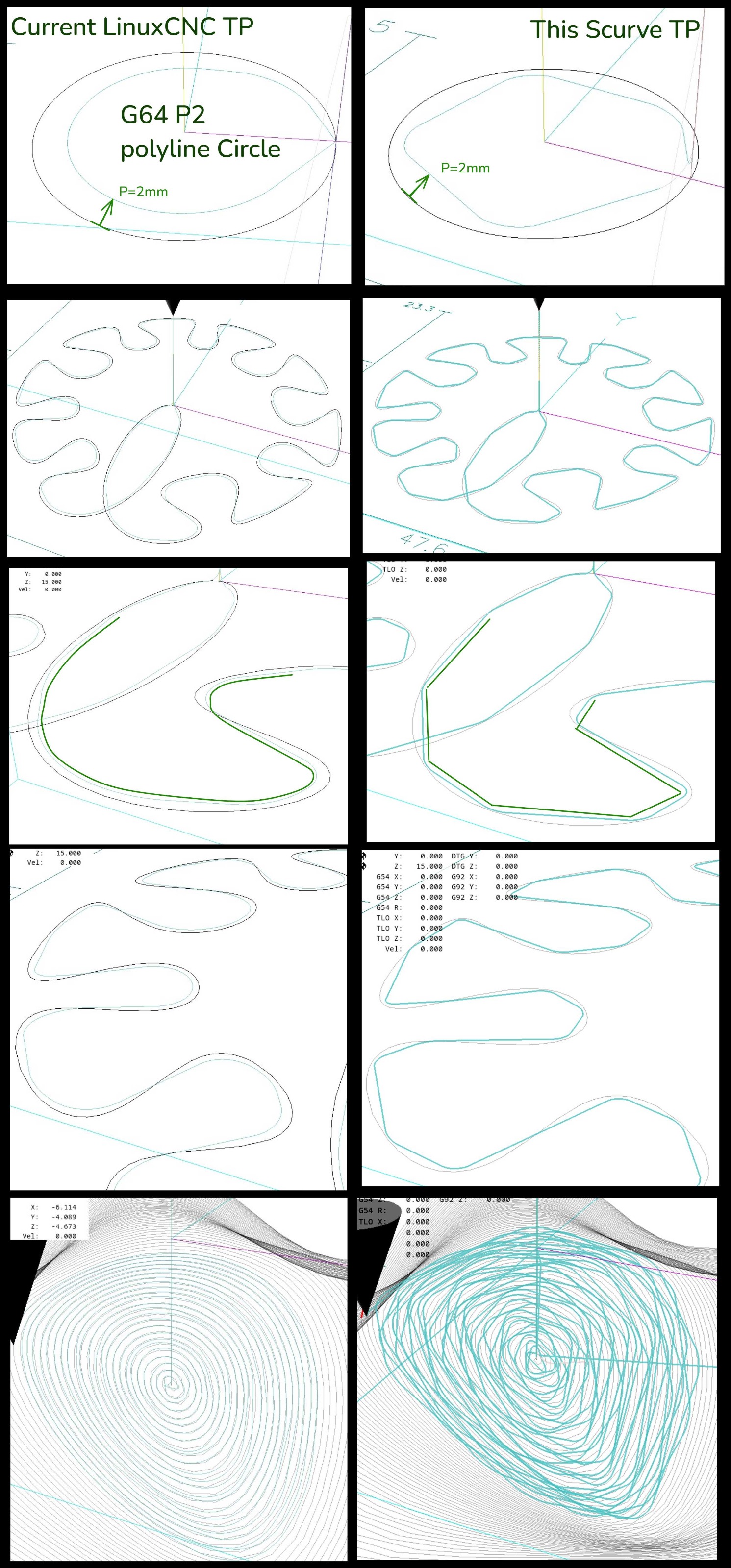
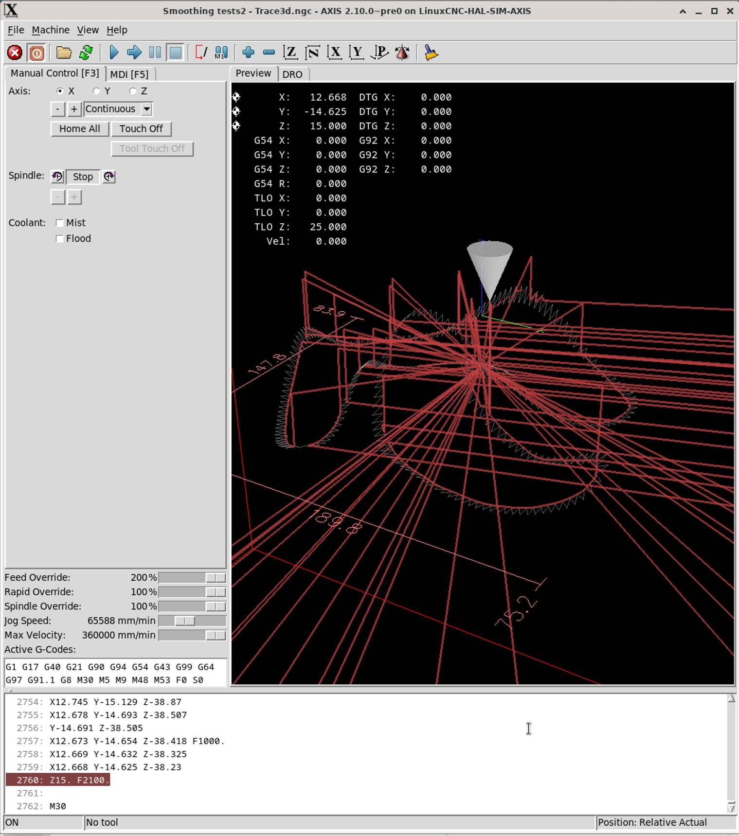
It shows that first the polyline is compressed by an algorithm similar to Douglas-Peucker, then the large lines are connected by a b-spline whose radius of curvature is limited by acceleration. This creates constant changes in velocity, acceleration and deceleration that are bad for milling. The most important thing for milling is to maintain a stable speed. The optimum solution would be to drive with minimum curvature over the entire trajectory. The last image shows the difference in 3D milling.
The old planner produces a path with minimal curvature, but it always tends to move inside the curve. A similar effect can be seen in this animation comparing "Moving Average" and "CCMA":
github.com/UniBwTAS/ccma/raw/master/figures/demo.gif
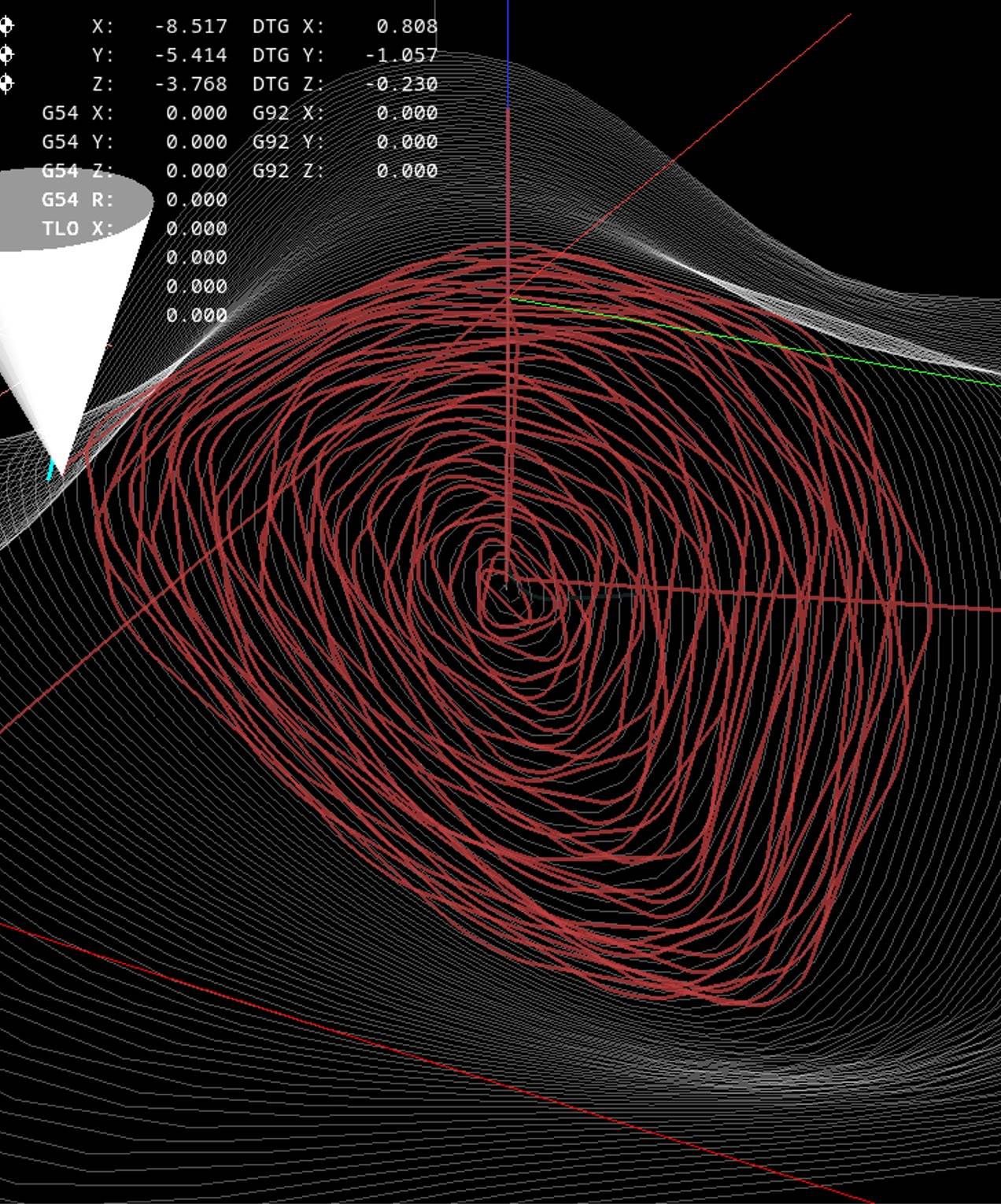
I also have a problem when the trajectory is plotted with a lot of smoothing errors - it randomly moves far outside the limits:
I can provide all the programs I used for the comparison, maybe it will help to fix the errors.
Replied by hmnijp on topic scurve trajectory planner
Yes. Such smoothing is not optimal. The value of P should certainly be the limit of deviation from the programmed path.I always set with a P value the maximum allowed deviation of a given path. So now I am not really sure. Can I just calculate something?
I am also concerned about the compression algorithm that creates polygons if you increase the ‘P’ value. I have prepared a comparison with the old path planner:
It shows that first the polyline is compressed by an algorithm similar to Douglas-Peucker, then the large lines are connected by a b-spline whose radius of curvature is limited by acceleration. This creates constant changes in velocity, acceleration and deceleration that are bad for milling. The most important thing for milling is to maintain a stable speed. The optimum solution would be to drive with minimum curvature over the entire trajectory. The last image shows the difference in 3D milling.
The old planner produces a path with minimal curvature, but it always tends to move inside the curve. A similar effect can be seen in this animation comparing "Moving Average" and "CCMA":
github.com/UniBwTAS/ccma/raw/master/figures/demo.gif
I also have a problem when the trajectory is plotted with a lot of smoothing errors - it randomly moves far outside the limits:
I can provide all the programs I used for the comparison, maybe it will help to fix the errors.
Attachments:
Last edit: 23 Jan 2025 09:47 by hmnijp.
The following user(s) said Thank You: tivoi, Darium
Please Log in or Create an account to join the conversation.
- hmnijp
- Offline
- Senior Member
-
Less
More
- Posts: 42
- Thank you received: 49
22 Jan 2025 15:17 - 22 Jan 2025 15:42 #319641
by hmnijp
Replied by hmnijp on topic scurve trajectory planner
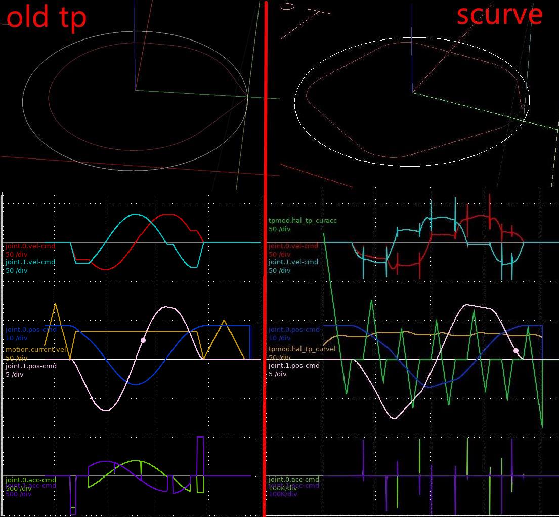
Another important issue is the jerk and acceleration at the segment junction.
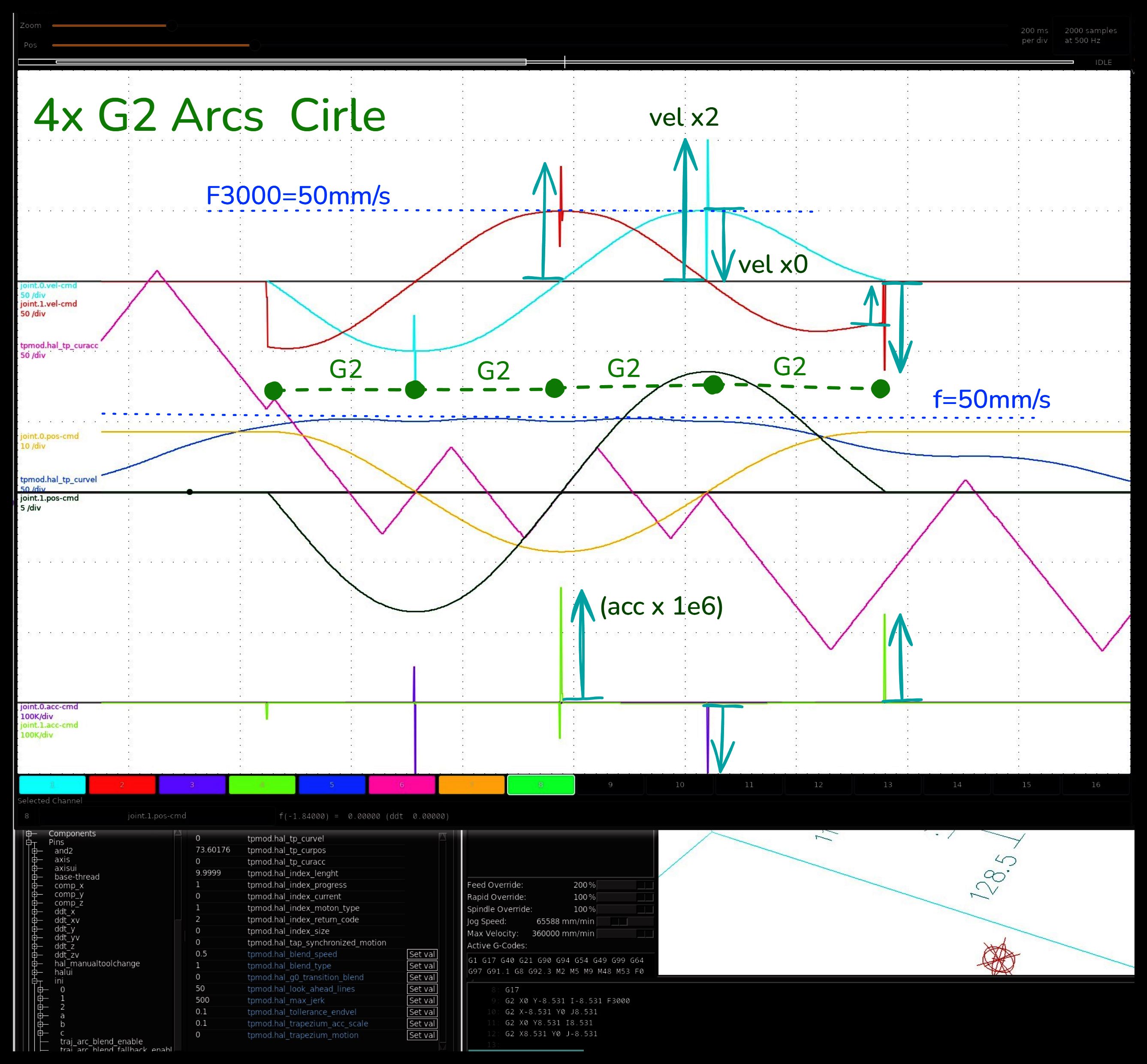
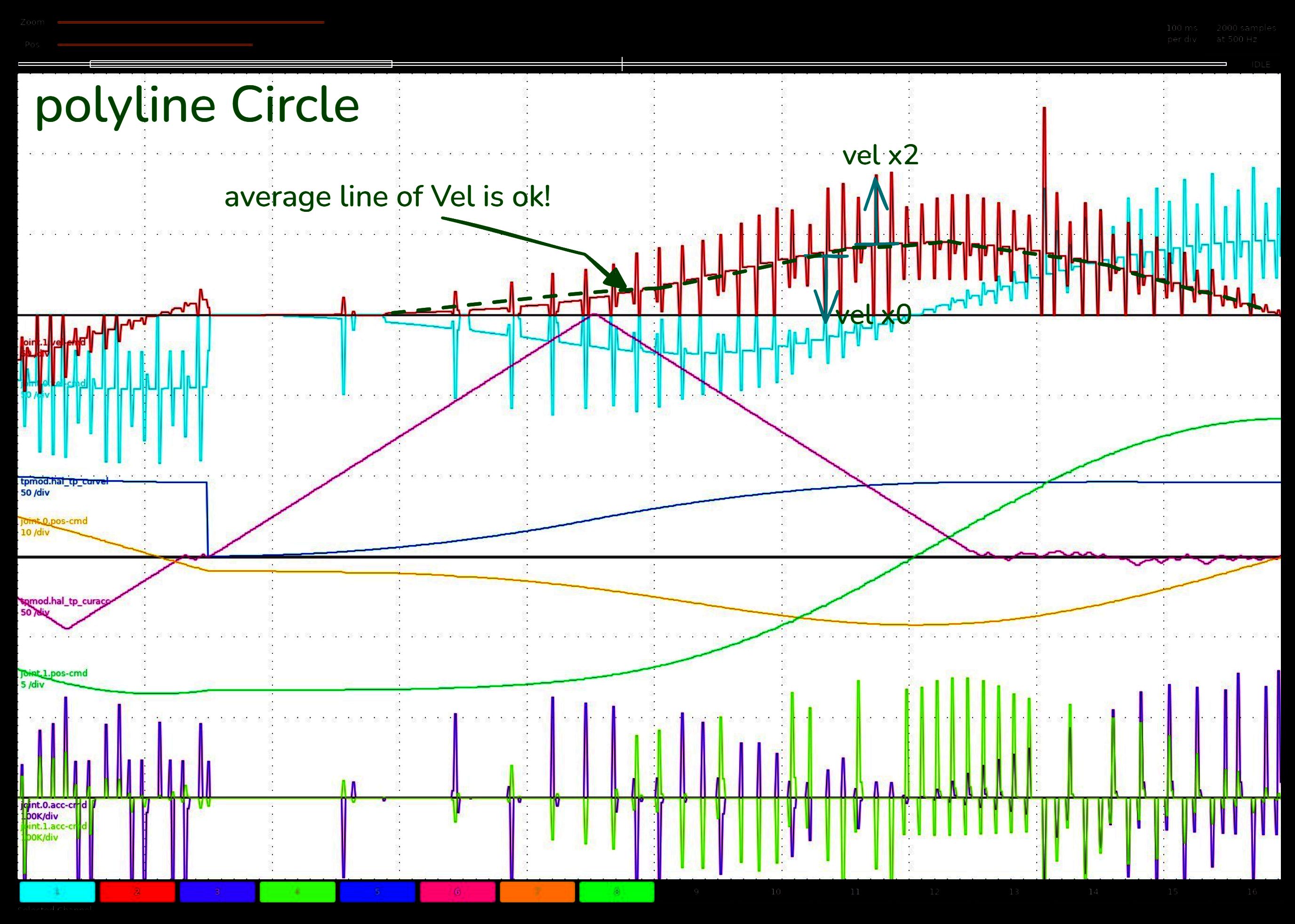
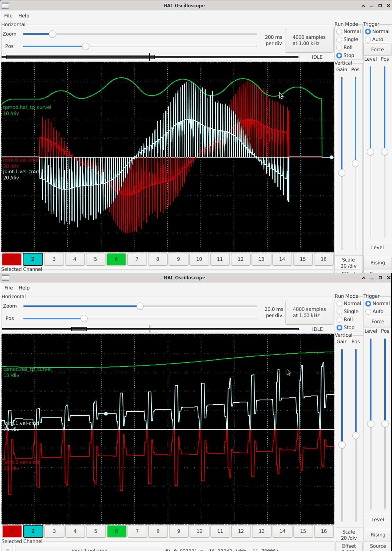
The coordinated velocity and acceleration values on the TP pins look correct. But the values for each axis individually have instantaneous velocity changes (0xVel to 2xVel) at the segment junction, and acceleration jerks that exceed the limits (over 100K). This looks like a calculation error.
On a polyline path it makes a jolt with a frequency of 10-100ms.
With this speed signal, the servos and PIDs go crazy and can't work.
And the last less important problem I saw is that on a non-realtime system TPMOD stops working when trying to load a programme larger than ~100-200 lines. Therefore, simulation and testing have to be performed only on a realtime system
I would like to express my gratitude. Thank you very much Grotius for doing a great job despite some problems that can be solved. The linuxcnc tp has been in need of improvement for a long time.
I can provide all the programs I used for the comparison, maybe it will help to fix the errors.
Attachments:
Last edit: 22 Jan 2025 15:42 by hmnijp.
The following user(s) said Thank You: tommylight, Grotius, Aciera, RDA, Beef, LCR
Please Log in or Create an account to join the conversation.
- juliankoenig87
- Offline
- Premium Member
-
Less
More
- Posts: 119
- Thank you received: 55
22 Jan 2025 16:02 #319643
by juliankoenig87
Replied by juliankoenig87 on topic scurve trajectory planner
Yes. It looks the same with my 4 axis machines. Normal tp works with different machine setups without a problem. The scurve tp jumps all over the place! But. Only if a fourth axis (rotary, A) is involved. 3 axis programms without a problem.
Looks also that the axis gui is not really "connected". Preview an tp are working without connection.
Looks also that the axis gui is not really "connected". Preview an tp are working without connection.
Please Log in or Create an account to join the conversation.
- ihavenofish
- Offline
- Platinum Member
-
Less
More
- Posts: 1013
- Thank you received: 285
22 Jan 2025 19:21 #319662
by ihavenofish
Replied by ihavenofish on topic scurve trajectory planner
hmmm
Please Log in or Create an account to join the conversation.
- Beef
-

- Offline
- Senior Member
-
Less
More
- Posts: 43
- Thank you received: 54
23 Jan 2025 11:26 - 23 Jan 2025 11:28 #319704
by Beef
Replied by Beef on topic scurve trajectory planner
I think this issue with the deviation being higher than the P value specifies may be resolved in the correct_trim_length() method, by calculating the angle between the segments and calculating this max_trim so that it doesn't exceed P. I have to do some more digging in the meantime and wrap my head around this.
The code is very readable and well commented.
void filletizer::correct_trim_length(const emcmot_segment& seg, double& max_trim){

    max_trim=seg.tag.fields_float[3]; // Gcode path deviation.

    // Trim conditions.
    if(max_trim<=1e-6){
        max_trim = 0;
    }

    // Let the trim be valid if done from both sides.
    if (max_trim >= (seg.length_netto * 0.5)) {
        max_trim = (seg.length_netto * 0.5)-1e-3;
    }
}
The code is very readable and well commented.
Last edit: 23 Jan 2025 11:28 by Beef.
The following user(s) said Thank You: Grotius
Please Log in or Create an account to join the conversation.
- Grotius
-
 Topic Author
- Offline
- Platinum Member
-
Less
More
- Posts: 2419
- Thank you received: 2348
23 Jan 2025 11:30 - 23 Jan 2025 11:52 #319705
by Grotius
Replied by Grotius on topic scurve trajectory planner
@Hmnijp,
Thank you for contribution.
Will first look into the joint.0 & joint.1 velocity spikes. As the planner is
not involved in calculating these values.
@Beef,
I already tested a spline using deviation.
I like the idea of Hmnijp, the industrial example.
Thank you for contribution.
Will first look into the joint.0 & joint.1 velocity spikes. As the planner is
not involved in calculating these values.
@Beef,
I already tested a spline using deviation.
I like the idea of Hmnijp, the industrial example.
Last edit: 23 Jan 2025 11:52 by Grotius.
The following user(s) said Thank You: Beef, hmnijp
Please Log in or Create an account to join the conversation.
Time to create page: 0.626 seconds