- Configuring LinuxCNC
- Basic Configuration
- How to connect Home switches for dual motor on 3 Axis machine [2.8 Pre Master]
How to connect Home switches for dual motor on 3 Axis machine [2.8 Pre Master]
- rodw
-

- Offline
- Platinum Member
-

Less
More
- Posts: 11990
- Thank you received: 4084
24 Jan 2018 11:44 #104935
by rodw
Replied by rodw on topic How to connect Home switches for dual motor on 3 Axis machine [2.8 Pre Master]
Great you are under way again. When I started to build my gantry machine about 10-12 months ago, not many people had used the new joint axis features so I had a long journey as nobody had much experience and there were still a few bugs floating around (mostly in the GUI's) but I think it has all been fixed and it will be plain sailing now. If in doubt update to the latest master branch as I do see it break from time to time and get fixed pretty quickly.
Please Log in or Create an account to join the conversation.
- denhen89
-
 Topic Author
- Offline
- Elite Member
-

Less
More
- Posts: 301
- Thank you received: 27
24 Jan 2018 14:51 #104937
by denhen89
Replied by denhen89 on topic How to connect Home switches for dual motor on 3 Axis machine [2.8 Pre Master]
Rod, you helped me already a lot and i very appriciate it very much, but I feel a bit bad because i thought i do understand the home sequence, but actually i dont know what is going on.
The Problem: When my gantry moves to the direction of the Proximity switches, and the switch on the right side gets activated, the motor still moves closer to the switch and does not stop like on the video from JohnT. The left side moves and searches the switch, but the whole gantry gets stuck, because the right side still moves instead of stopping when the right switch is activated.
Some info: I had to invert the left motor (y1), because it moved in the opposite direction then the right motor (y2).
The home switches for the gantry are not on the front side of the router, they are on the back side, because it was easier to mount the switches there (no need to use long wires and hide them in the steel tubing) and also they would be a bit disturbing on the front side.
Home sequence for the gantry joints are both set to -1.
In attachment i uploaded the .ini file and also the hal file but i think only the ini is important.
Please Log in or Create an account to join the conversation.
- Clive S
- Offline
- Platinum Member
-
Less
More
- Posts: 2204
- Thank you received: 486
24 Jan 2018 16:49 - 24 Jan 2018 16:51 #104943
by Clive S
Replied by Clive S on topic How to connect Home switches for dual motor on 3 Axis machine [2.8 Pre Master]
Take what I say with a pinch of salt. I see in the hal file you have E-stop on pin 10 and Y2 home on pin 15 personally I would swap them around as some bob's like the E-stop on pin 15. Does the E-stop work?
I am looking forward to this being resolved
I am looking forward to this being resolved
Last edit: 24 Jan 2018 16:51 by Clive S.
Please Log in or Create an account to join the conversation.
- denhen89
-
Topic Author
- Offline
- Elite Member
-
Less
More
- Posts: 301
- Thank you received: 27
24 Jan 2018 16:55 #104944
by denhen89
Replied by denhen89 on topic How to connect Home switches for dual motor on 3 Axis machine [2.8 Pre Master]
Hi Clive,
thanks for your reply.
The e-stop works properly. The problem is just that the y2 motor continues to move instead of stopping when activating the proximity switch.
Unfortunately i have to go out with my dog now and will be back in about 1 1/2 hours. I will then test what you wrote and swap estop with pin15 (y2 home).
Please Log in or Create an account to join the conversation.
- rodw
-
- Offline
- Platinum Member
-
Less
More
- Posts: 11990
- Thank you received: 4084
24 Jan 2018 19:00 - 24 Jan 2018 19:11 #104945
by rodw
Replied by rodw on topic How to connect Home switches for dual motor on 3 Axis machine [2.8 Pre Master]
At times like this, I always start at the beginning in halshow to make sure the signals I am using are turning on and off as expected.
I would make sure that the home switch is actually where you think it is. I changed my machine geometry around and realised that I'd inadvertently swapped the stepper wiring plugs around so the home switch was on the wrong side to the stepper and I had similar behaviour to what you describe... It was hard to debug as it had been working before but when I really slowed down the velocities, I could see the problem.
Also, I found that the prox switches required to be enabled while the machine decelerates to a stop. This is why I devised limit switches that looked like this with 100 mm of travel so it could come to a stop
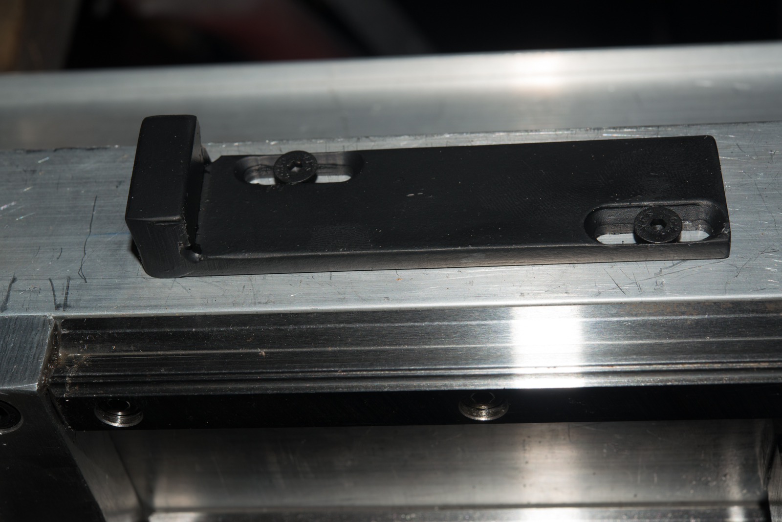
3 prox switches mounted on the gantry.. Outer ones are limit switches and inner one is the home sensor.
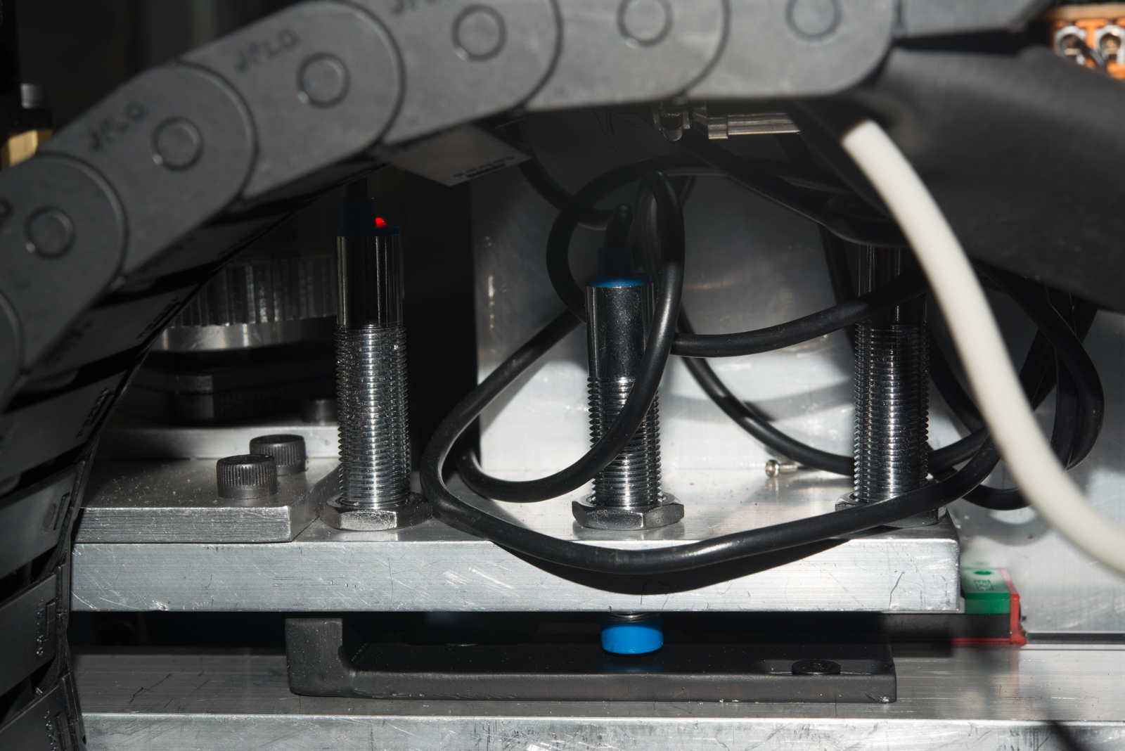
This worked so well I mounted them on the gantry in exactly the same way.
You can see the limit switch plate poking out to the right and the home prox switch hiding on the left of the black cable with the limit switches on the outer edges of the gantry .
Your ini homing settings look OK to me. Here is mine
EDIT: Its worth noting on the second photo that the HOME_OFFSET has moved the gantry away from the edge of the sensing plate where the home position was sensed to use as much of the gantry travel as I could without the limit switch being triggered.
I would make sure that the home switch is actually where you think it is. I changed my machine geometry around and realised that I'd inadvertently swapped the stepper wiring plugs around so the home switch was on the wrong side to the stepper and I had similar behaviour to what you describe... It was hard to debug as it had been working before but when I really slowed down the velocities, I could see the problem.
Also, I found that the prox switches required to be enabled while the machine decelerates to a stop. This is why I devised limit switches that looked like this with 100 mm of travel so it could come to a stop
3 prox switches mounted on the gantry.. Outer ones are limit switches and inner one is the home sensor.
This worked so well I mounted them on the gantry in exactly the same way.
You can see the limit switch plate poking out to the right and the home prox switch hiding on the left of the black cable with the limit switches on the outer edges of the gantry .
Your ini homing settings look OK to me. Here is mine
HOME_OFFSET = 45
HOME_SEARCH_VEL = -100
HOME_LATCH_VEL = 10
HOME_FINAL_VEL = 50
HOME_USE_INDEX = NO
HOME_SEQUENCE = -1
EDIT: Its worth noting on the second photo that the HOME_OFFSET has moved the gantry away from the edge of the sensing plate where the home position was sensed to use as much of the gantry travel as I could without the limit switch being triggered.
Last edit: 24 Jan 2018 19:11 by rodw.
Please Log in or Create an account to join the conversation.
- denhen89
-
Topic Author
- Offline
- Elite Member
-
Less
More
- Posts: 301
- Thank you received: 27
24 Jan 2018 19:25 #104947
by denhen89
Replied by denhen89 on topic How to connect Home switches for dual motor on 3 Axis machine [2.8 Pre Master]
Hi,
i just went back home and the first thing i wanted to check if the motor on left (Y1) does stop when activating the switch, and yes, it does stop but not the right motor (Y2). So, i then did what you wrote, to check if the signals are turning on and off from the switches on the halmeter and i found something out:
When the switch is activated there is an red light which turns on and the Halmeter shows "FALSE". When the switch is not activated, it shows "TRUE". In my case, only the left home switch (Y1) does change from TRUE to FALSE when the switch is activated, but the Y2 switch does nothing. Its always on FALSE, no matter if the switch is activated or not, so if i do understand correctly, there might be something wrong with the switch or with the wire.
I do use Microphone connectors for the switches and 2 days ago i already had already an problem and saw that the wire went of the connector, and it might be thats now also the problem, but i dont understand why it shows FALSE, even its not activated. It should be TRUE when not activated.
Thanks for the info that the INI Homing settings looks okay. Its seems that i have to check the wires.
Please Log in or Create an account to join the conversation.
- rodw
-
- Offline
- Platinum Member
-
Less
More
- Posts: 11990
- Thank you received: 4084
24 Jan 2018 19:29 #104948
by rodw
Replied by rodw on topic How to connect Home switches for dual motor on 3 Axis machine [2.8 Pre Master]
there should be a version of your pin with a not at the end of its name which inverts the state of the signal. Looking in Halshow should show it. If not, you can use the invert component to swap the state of the pin.
Some prox sensors are normally open and others normally closed. You may also need a pull down or pullup resistor on some prox sensors. eg on my mesa hardware NPN sensors requires a pullup resistor, PNP does not.
Some prox sensors are normally open and others normally closed. You may also need a pull down or pullup resistor on some prox sensors. eg on my mesa hardware NPN sensors requires a pullup resistor, PNP does not.
Please Log in or Create an account to join the conversation.
- Mike_Eitel
-

- Offline
- Platinum Member
-
Less
More
- Posts: 1052
- Thank you received: 183
24 Jan 2018 19:51 #104951
by Mike_Eitel
Replied by Mike_Eitel on topic How to connect Home switches for dual motor on 3 Axis machine [2.8 Pre Master]
Do i understand right that u use a printerport?
Are your sure your switches are compatible to 5 volts. Often that is their low limit.
Use voltmeter and control if both sensors provide same "low" level...
And as Rodw wrote, consider pull-up/down resistors.
Are your sure your switches are compatible to 5 volts. Often that is their low limit.
Use voltmeter and control if both sensors provide same "low" level...
And as Rodw wrote, consider pull-up/down resistors.
Please Log in or Create an account to join the conversation.
- denhen89
-
Topic Author
- Offline
- Elite Member
-
Less
More
- Posts: 301
- Thank you received: 27
24 Jan 2018 20:16 - 24 Jan 2018 20:22 #104953
by denhen89
Replied by denhen89 on topic How to connect Home switches for dual motor on 3 Axis machine [2.8 Pre Master]
So, thanks guys, i have some information and i think after those information you will be able to tell me if i need an resistor or not, but i will need to edit the post soon to add some pictures via smartphone, but i will explain as good as possible.
So, my proximity home switches (PND NO) are connected seperatly. Each switch has its on terminal where the Black signal wire goes in. The switches need 6-36 VDC. I use an external 12V/3A PSU for the Limit switches, because the BOB gives only 5V on this terminal block, so there is only the Estop connected to 5V and GND.
Switches have 3 Wires. Black, Blue, Brown.
Brown goes to + on Supply,
Blue goes to - on Supply.
Black goes to BOB.
Blue wire from - Supply goes to GND of the BOB.
The Terminal-block from left to right (on the picture its not visible due to the connected wires):
HMA+, HMA-, GND, 5V, Z HOME, Y HOME, X HOME, E-STOP
X Home is connected to X Home terminal
Y1 Home is connected to Y Home terminal
Z Home is connected to Z Home terminal
Y2 Home is connected to HMA+ terminal
one (blue) wire is connected from HMA- terminal to GND terminal (blue wire, see picture)
I checked if the wires from the home switches are nowhere broken, by checking volt from GND to HMA+, Z Home, Y Home and X home.
When switch is off, there is 0V, when switch is on there is 15V. (Y2 home gives exactly 15.00V, Y1 home gives 14.25V.)
No the problem or what is actually going on:
Like i already wrote in my last post, the Y2 switch does not change from TRUE to FALSE when it gets triggered, it always stays on FALSE like it would be triggered (dont understand why the Y2 motor even moves if it is on FALSE, because Y1 stops if triggered switch and is on "FALSE".
Next thing i did, was to take of the BLUE wire which connected terminal HMA- and GND, and then Y2 Home switched from FALSE to TRUE, but now is stays permanently on TRUE and not anymore permanently on FALSE.
I am not sure if that means that i need an Resistor only on that switch?
EDIT: Mike_Eitel, yes i am using an Parallel Port BOB. The switches are connected to an external 12V/3A PSU.
Not sure now if i need an resistor on the Y2 Home switch (HMA+ terminal). If so, which one, pull-up or down resistor?
Last edit: 24 Jan 2018 20:22 by denhen89.
Please Log in or Create an account to join the conversation.
- Mike_Eitel
-
- Offline
- Platinum Member
-
Less
More
- Posts: 1052
- Thank you received: 183
24 Jan 2018 20:44 #104956
by Mike_Eitel
Replied by Mike_Eitel on topic How to connect Home switches for dual motor on 3 Axis machine [2.8 Pre Master]
I'm puzzled.
I have severe problems to see 15V ( from a 12 V PSU ????) on a printerport input! Killer!
My feeling is that you have had good luck(until now) not to burn your printerport!
Maybe as your psu is not ground connected to bob?
Or is it a galvanic separating bob?
If you really have to feed sensor with more than the allowed input level, make it by a usual trick of the tiny voltage regulator 78H05. vdd= input is your black wire, gnd is your gnd, and output of regulator drives a f.x. 1k resistor to gnd, parallel to your bob input.
Please Log in or Create an account to join the conversation.
- Configuring LinuxCNC
- Basic Configuration
- How to connect Home switches for dual motor on 3 Axis machine [2.8 Pre Master]
Time to create page: 0.245 seconds