Touch Plate Explanation please
- Aciera
-

- Offline
- Administrator
-

Less
More
- Posts: 4724
- Thank you received: 2117
30 Nov 2020 14:25 #190681
by Aciera
Replied by Aciera on topic Touch Plate Explanation please
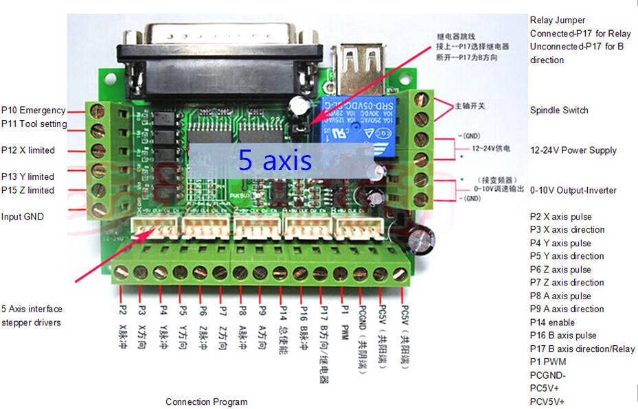
Any information as to which pin the BOB wants the pwm (spindle speed) signal from the parallel port?
This one?
This one?
Attachments:
Please Log in or Create an account to join the conversation.
- shortcircuit48
- Offline
- Premium Member
-

Less
More
- Posts: 131
- Thank you received: 3
30 Nov 2020 14:29 - 30 Nov 2020 14:30 #190682
by shortcircuit48
Replied by shortcircuit48 on topic Touch Plate Explanation please
Yes, identical. My inverter can take an analogue input or RS485
Last edit: 30 Nov 2020 14:30 by shortcircuit48.
Please Log in or Create an account to join the conversation.
- Aciera
-
- Offline
- Administrator
-
Less
More
- Posts: 4724
- Thank you received: 2117
30 Nov 2020 14:37 #190683
by Aciera
Replied by Aciera on topic Touch Plate Explanation please
Aha, then your pin assignments are wrong.
This is what you have in "Router.hal" Lines 42 to 63:
Your BOB wants the PWM (Spindle speed) signal on Pin1 so you need to assign the signal "spindle-pwm" to pin1.
So do this:
change line 42 to:
change line 58 to:
Save and run.
This is what you have in "Router.hal" Lines 42 to 63:
net estop-out       => parport.0.pin-01-out
net xstep           => parport.0.pin-02-out
setp parport.0.pin-02-out-reset 1
setp parport.0.pin-03-out-invert 1
net xdir            => parport.0.pin-03-out
net ystep           => parport.0.pin-04-out
setp parport.0.pin-04-out-reset 1
setp parport.0.pin-05-out-invert 1
net ydir            => parport.0.pin-05-out
net zstep           => parport.0.pin-06-out
setp parport.0.pin-06-out-reset 1
net zdir            => parport.0.pin-07-out
net astep           => parport.0.pin-08-out
setp parport.0.pin-08-out-reset 1
net adir            => parport.0.pin-09-out
net spindle-cw      => parport.0.pin-14-out
net spindle-pwm     => parport.0.pin-16-out
net xenable         => parport.0.pin-17-out
net estop-ext       <= parport.0.pin-10-in
net probe-in        <= parport.0.pin-11-in-not
net home-x          <= parport.0.pin-12-in
net home-y          <= parport.0.pin-13-in
Your BOB wants the PWM (Spindle speed) signal on Pin1 so you need to assign the signal "spindle-pwm" to pin1.
So do this:
change line 42 to:
net estop-out => parport.0.pin-16-outchange line 58 to:
net spindle-pwm => parport.0.pin-01-outSave and run.
Please Log in or Create an account to join the conversation.
- shortcircuit48
- Offline
- Premium Member
-
Less
More
- Posts: 131
- Thank you received: 3
30 Nov 2020 18:46 #190696
by shortcircuit48
Replied by shortcircuit48 on topic Touch Plate Explanation please
Followed instructions and now GUI works as it should be with now being able to use probe.
Unfortunately I have made very heavy weather with controlling the spindle. I had previously manually switched it off/on from the inverter but that alluded it. Not something I spend a lot of time on but eventually enabled it to switch off and on manually. Programmed off/on via PWM connection and although I get a change in voltage up to about 4 volts nothing happens. Something silly (XSY-AT1-2200X)
Unfortunately I have made very heavy weather with controlling the spindle. I had previously manually switched it off/on from the inverter but that alluded it. Not something I spend a lot of time on but eventually enabled it to switch off and on manually. Programmed off/on via PWM connection and although I get a change in voltage up to about 4 volts nothing happens. Something silly (XSY-AT1-2200X)
Please Log in or Create an account to join the conversation.
- Aciera
-
- Offline
- Administrator
-
Less
More
- Posts: 4724
- Thank you received: 2117
30 Nov 2020 19:50 - 30 Nov 2020 20:00 #190702
by Aciera
Replied by Aciera on topic Touch Plate Explanation please
Well the PWM is not really meant to switch the spindle on and off. The pwm is for controlling the spindle speed by way of the 0-10V analog output. Spindle on/off is by way of the "Spindle Switch" relay contact on your BOB. And that in turn is controlled through Pin 17 if the Jumper on the BOB is in place. I'll have to check about the connection in Router.hal...
[edit]
So this is not correct.
replace with:
Then of course you will have to wire the vfd up correctly and probably also set the parameters accordingly.
[edit]
Maybe this helps?
www.mycncuk.com/threads/12091-XSY-AT1-VF...speed-wiring-enquiry
[edit]
So this is not correct.
net xenable => parport.0.pin-17-out
replace with:
net spindle-on => parport.0.pin-17-out
Then of course you will have to wire the vfd up correctly and probably also set the parameters accordingly.
[edit]
Maybe this helps?
www.mycncuk.com/threads/12091-XSY-AT1-VF...speed-wiring-enquiry
Last edit: 30 Nov 2020 20:00 by Aciera.
Please Log in or Create an account to join the conversation.
- shortcircuit48
- Offline
- Premium Member
-
Less
More
- Posts: 131
- Thank you received: 3
30 Nov 2020 20:17 #190704
by shortcircuit48
Replied by shortcircuit48 on topic Touch Plate Explanation please
I have a fault report to say net spindle-on => parport.0.pin-17-out this action already done so I will comment out
Please Log in or Create an account to join the conversation.
- shortcircuit48
- Offline
- Premium Member
-
Less
More
- Posts: 131
- Thank you received: 3
30 Nov 2020 20:48 - 30 Nov 2020 22:22 #190706
by shortcircuit48
Replied by shortcircuit48 on topic Touch Plate Explanation please
\Now able to switch spindle manually off/on through GUI or by running a programme. Hopefully I will be able to vary the speed also, but that is a task for another day.
Quite amazed at the number of views this post has had, so possible a lot more like me learning.
Again a big thanks for your help
Quite amazed at the number of views this post has had, so possible a lot more like me learning.
Again a big thanks for your help
Last edit: 30 Nov 2020 22:22 by shortcircuit48.
Please Log in or Create an account to join the conversation.
- shortcircuit48
- Offline
- Premium Member
-
Less
More
- Posts: 131
- Thank you received: 3
14 Nov 2021 19:03 - 14 Nov 2021 19:05 #226502
by shortcircuit48
Replied by shortcircuit48 on topic Touch Plate Explanation please
Having been diverted to other projects I have come back to using my router, well nearly. I can set it up as normal and all is ok. Having used the probe before I decided to use it again but I cannot get it to work. I am using the Gmoccapy platform, on which it did work, following previous advice given. The program loads but I am unable to home or probe. Not sure what I have done but would be very grateful for assistance.
Attach files that I hope are appropriate
Attach files that I hope are appropriate
Attachments:
Last edit: 14 Nov 2021 19:05 by shortcircuit48. Reason: Spelling
Please Log in or Create an account to join the conversation.
- shortcircuit48
- Offline
- Premium Member
-
Less
More
- Posts: 131
- Thank you received: 3
15 Nov 2021 09:01 #226557
by shortcircuit48
Replied by shortcircuit48 on topic Touch Plate Explanation please
I think I posted the wrong Router.ini file. Will try again.
Attachments:
Please Log in or Create an account to join the conversation.
- shortcircuit48
- Offline
- Premium Member
-
Less
More
- Posts: 131
- Thank you received: 3
15 Nov 2021 17:51 - 22 Nov 2021 11:44 #226593
by shortcircuit48
Replied by shortcircuit48 on topic Touch Plate Explanation please
After a good bit more trial and error I find I can home Z. When I attempt to home X&Y the display still remains red and the value increases and I assume if the joints were connected would run.(No limit switches used) Attempting to probe has no effect.
Hope this might provide a clue.
Edit This is garbage
Hope this might provide a clue.
Edit This is garbage
Last edit: 22 Nov 2021 11:44 by shortcircuit48.
Please Log in or Create an account to join the conversation.
Time to create page: 0.864 seconds