Search Results (Searched for: 7i77 spindle)
- JThom
- JThom
09 Jul 2026 16:34
Colchester 4000L retrofit was created by JThom
Colchester 4000L retrofit
Category: Turning
Hello,
I'm investigating a lathe retrofit on a Colchester 4000L Fanuc 0T-A.
I've done a couple of retrofit/hybrid, and 'from scratch' LinuxCNC machines before, but none involving Fanuc, which I know is often difficult-to-impossible depending on the particulars. I've looked at numerous paths forward balancing time/difficulty vs up-front cost.
Been reading old manuals, searching the forums, and I must admit, taking a significant amount of input from ai, and I have a plan. But, while it was nice to seemingly make rapid progress compared to my previous projects, I would be glad of input from other actual humans. If CNC has taught me anything, it's don't trust a machine! I've tried to include enough relevant detail without turning the post into War and Peace.
===
I'll be using MESA boards - most likely a 7i96 connected to a 7i77. I already have them from a previous project where they worked very well.
For axes, I want to keep the Fanuc motors (red caps: A06B-0513-B032#7000 amd A06B-0512), and (for now) their drive/VCU (it's a dual axis unit A16B-1200-0520).
If I've understood correctly, LinuxCNC can read the positional feedback from the encoders via serial port on the 7i77, then using DC injection to find the magnetic offset, generate commutation data and command the motor via 7i77's 10V into the pre-existing VCU.
I'll Keep the fanuc spindle motor, an 11kW A06B-0745-B201, which seemingly has an encoder with ABZ output that LinuxCNC can use via encoder input on the 7i77.
I'm replacing the spindle-driver/VCU (A06B-6060-H008) with a heavy duty VFD. Something like a Yaskawa GA70C2056BBA. The failing fanuc spindle driver is actually the straw that broke the camel's back and instigated this project.
Toolcahanger is a duplomatic BSV-160. There seems to be ample history for successfully using similar units.
Coolant pump is either on or off, I think it'll be OK.
Control will initially be primarily PC based, probably some touch-screen, but will probably add a pendant for easier manual positioning and the dopamine hit of pushing real buttons.
Really just wondering if anything is obviously foolish.
- umerov
- umerov
29 Jun 2026 14:19 - 29 Jun 2026 14:27
Request custom bitfile: 5i25 + 7i77 (P3) + 7i74 (P2) with pktUART for Modbus was created by umerov
Request custom bitfile: 5i25 + 7i77 (P3) + 7i74 (P2) with pktUART for Modbus
Category: Driver Boards
I am retrofitting an old Morbidelli CNC woodworking machine. My old setup used analog 0-10V to control the spindle inverter, but I would like to switch to Modbus RTU using an unused channel on my 7I74 card.
I checked the standard Mesa firmware archive but couldn't find a bitfile with the pktUART module for this exact hardware combination. Could PCW or someone else kindly compile a custom bitfile for me with 1 or 2 channels of pktUART on the 7I74, leaving the rest as standard SSerial?
My current hardware configuration is:
5I25 (P3) -> 7I77
5I25 (P2) -> 7I74
Thanks in advance for the help!
I checked the standard Mesa firmware archive but couldn't find a bitfile with the pktUART module for this exact hardware combination. Could PCW or someone else kindly compile a custom bitfile for me with 1 or 2 channels of pktUART on the 7I74, leaving the rest as standard SSerial?
My current hardware configuration is:
5I25 (P3) -> 7I77
5I25 (P2) -> 7I74
- 7I74 (Channel 0) -> 7I84 (inputs/outputs)
- 7I74 (Channel 1) -> 7I70 (inputs)
- 7I74 (Channel 2) -> 7I71 (outputs)
Thanks in advance for the help!
- grossm5000
- grossm5000
31 May 2026 18:33
Replied by grossm5000 on topic Differential encoder hard crashes the PC MESA7i77
Differential encoder hard crashes the PC MESA7i77
Category: Driver Boards
ok guys, overwhelming responses!! Thank you all for the awesome support!!
I do have a spindle, z, and x encoder, all attached to servo drives. I do not have the drives powered right now because I do not want to attach anything else for fear that I've done something wrong in the config/pin out. I can afford to replace an MPG, I cannot afford to replace a drive...
The original MPGs that came with the machine (Fryer ET18) are labeled as OLM-01-2AD by Maxmar Controls Inc. I presumed (as unlikley as it was) that both MPGs were bad because they both (X and Z) would crash the computer if they moved even one pulse.
The replacement MPGs are no-name Chinese, but are also 6 wire, 5VDC differential encoders. Pictures of those are in my previous posts. It doesnt appear to matter though, the new encoders make the machine behave the same as the old encoders. I am unable to find an official spec sheet for these, but the google claims they are standard quadrature A/B rotary MPG 5VD.
- agant172
- agant172
17 May 2026 18:31
Mesa conversion for a Mazak VQC 20/40 M2 mill was created by agant172
Mesa conversion for a Mazak VQC 20/40 M2 mill
Category: Driver Boards
Hi all,
Hoping this is the right place for a conversation about machine controller conversions. I'm a hobby user, not a production shop. I've got a Mazak VQC 20/40 mill with M2 control, it's a nice fully functional machine with good tolerances for it advanced age. It's lack of memory is a real pain point. Programming in Mazatrol CAM M2 was probably great back in the day, not so much now. I can send G-Code files to it, but hit file size limits rather quickly. It's not capable of drip feed. I think I'm ready to go for the Mesa upgrade. With AI help I've input all the info I can think of, this is where I'm at... realistic? reasonable?
Servo Motors & Drives:
X-axis: Mitsubishi HD-81-12 DC permanent magnet servo motor with analog drive accepting ±10V command (terminals: AX, BX, G1X, G2X, G)
Y-axis: Mitsubishi HD-81-12S DC PM servo with analog drive (terminals: AY, BY, G1Y, G2Y, G)
Z-axis: Mitsubishi HD-101-12 DC PM servo with analog drive (terminals: AZ, BZ, G1Z, G2Z, G)
All three drives are MELDA-8 or similar Mitsubishi analog cards that accept ±10V command signals—these are REUSABLE
Position Feedback:
X-axis: Magnescale SR-921RH linear encoder (outputs quadrature signals directly) + MS3100B 20-29P tacho generator
Y-axis: Tamagawa Seiki resolver (MS3108B 20-29P, pins: RS1, RS2, RC1, RC2, RO1, RO2) + tacho generator
Z-axis: Magnescale SR-921RH-450-R-0 linear encoder + MS3108B 20-29P tacho generator
Spindle:
Mitsubishi AC motor SE-EV-FV with FREQROL FR-SX VFD controller
Already accepts 0-10V analog speed command and direction signal—fully LinuxCNC compatible
Tool Changer:
20-tool carousel ATC with CAT40 tooling
Nachi proximity sensors for position detectionMesa Hardware StackCore Cards
7i92H - Ethernet-based motion controller, main brain
7i77 - 6-axis ±10V analog outputs + encoder inputs + 48 I/O points
7i49 - 6-channel resolver interface (for Y-axis only)
7i73 - Pendant/operator panel interface
Servo Drive Connections:
Existing 24VDC power supply (HR-11F, outputs P24 and G24) remains in service:
Mesa 7i77 I/O is 24V compatible
Existing Contactors (3S-1, 3S-2, 3S-3, 3S-4):
Control servo drive enable sequencing
Spindle power control
Lube/coolant pump control
These stay and get controlled through Mesa 7i77 I/O outputsATC IntegrationInputs to LinuxCNC:
Tool-in-position sensors (Nachi proximity switches)
Carousel rotation feedback
Gripper open/close confirmation
Drawbar clamp/unclamp sensors
Outputs from LinuxCNC:
Carousel motor control (forward/reverse)
Gripper solenoid
Drawbar solenoid
Air blast control
- Becksvill
- Becksvill
22 Apr 2026 21:05
Replied by Becksvill on topic Large FIL cnc machine retrofit. (12 ton larger maching running linuxcnc)
Large FIL cnc machine retrofit. (12 ton larger maching running linuxcnc)
Category: Show Your Stuff
more photosThis hydraulic system really stumped me until i asked a friend (thanks Gordon if you see this)
It has a accumulator so what you do is you turn the pump on and then wait until the pressure switch triggers and turn pump off. This machine only needs oil when toolchanging so it’s a great idea really and allows me to not need a pump running all the time. Once I worked out how it worked it is great and very easy to setup in classic ladder
next thing i need to talk about is how i am handling homing currently
this is just copied and pasted from the email user list. great place to get fast answers to questions btw
This email address is being protected from spambots. You need JavaScript enabled to view it.
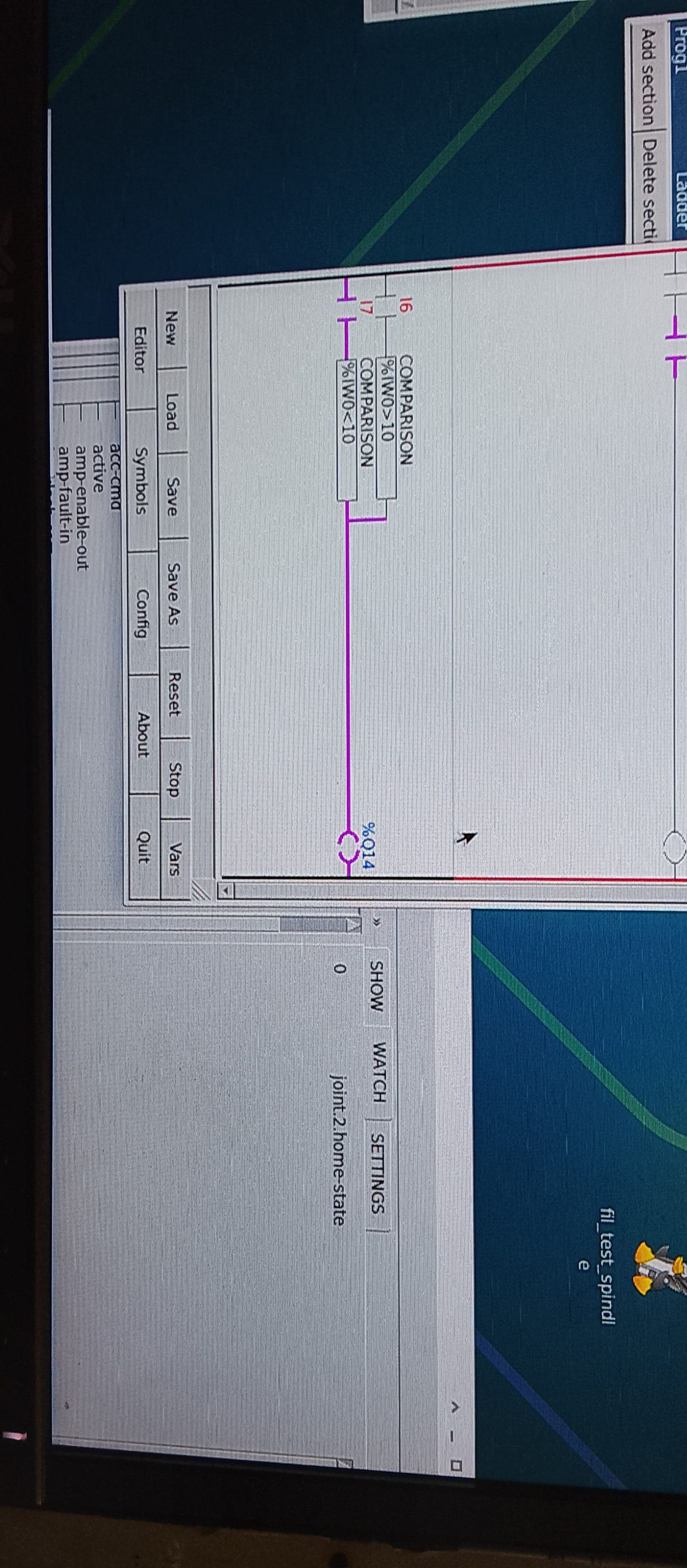
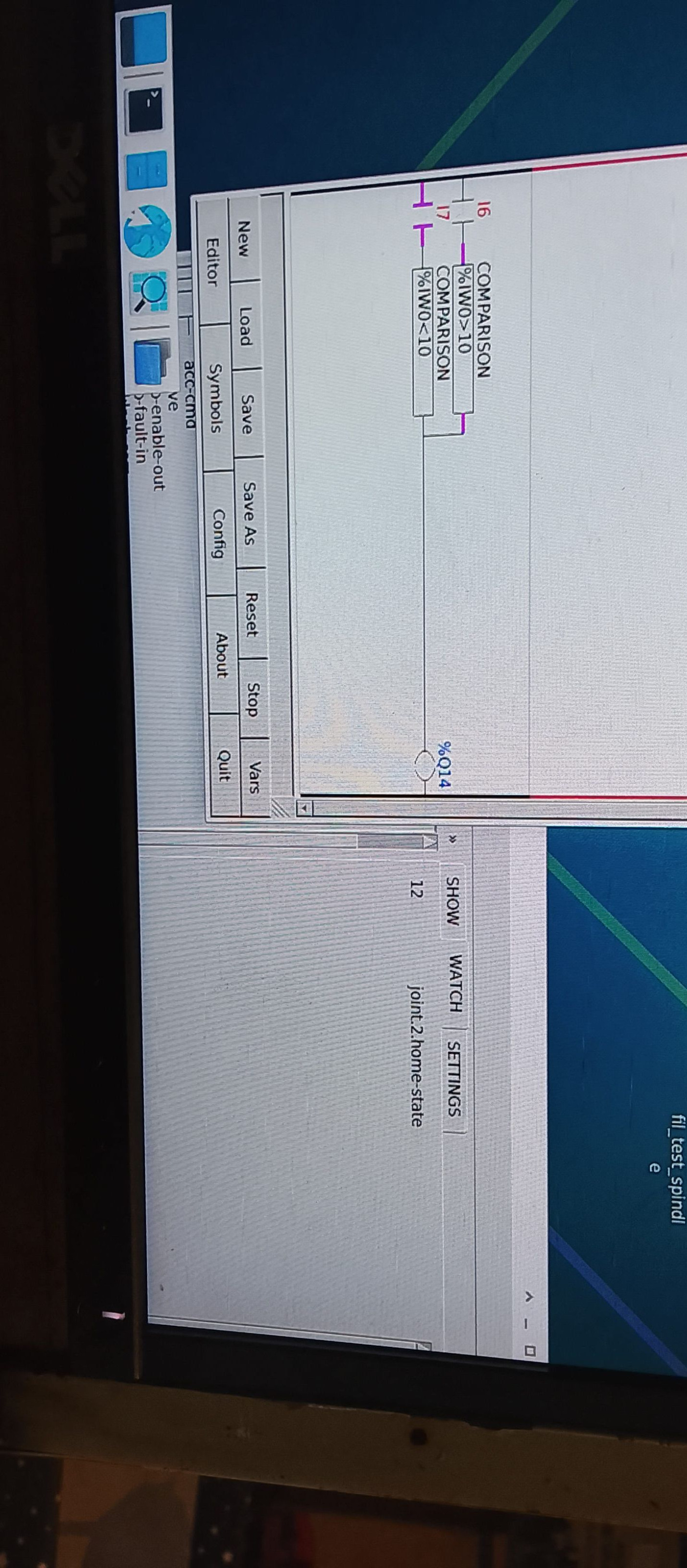
Hey guysthanks for the replies the homing is a interesting issue I had a bit of a play and made a copy of my config that i hacked. What i found was that if i combined my original 2 PID loops into 1 loop and used the scale for position and used the motor velocity on encoder for velocity all in one PID then homing to index enable worked perfectly. but doing it that way the motor tuning was not as good. backlash is a constant of 0.1mm and the motor just jumped across that backlash whenever it moved. in practice that meant that the absolute scale position hovered by +-0.01 or so. this was not bad and totally usable. If i had done this option first i would have called it good and just used it. but the movement was much louder and less smooth than the two PID loops which get run through a sum component. As the original two PID loops was much much smoother, it was perfect and once i come to a stop the drive rapids to within 0.01 or 0.02 and then creeps the last 0.02mm (using the integral value which takes about a second) and ends up in the right place within 0.005mm or less. basically perfect every time with no dithering. It is now my most accurate machine. and really nice also the homing when homing I home all axis at the same time. X and Y get homed to index enable like normal. and the Z value i trick the home switch by checking the joint state. How this works is the Joint2 switch state goes form 7 when searching for switch the first time to 12 when latching on to switch slowly the second time so in classic ladder i set up two compare functions that basically choose whether to listen to the main home switch or the z axis motor encoder Z index pulse. (this is different to the index enable pulse and this is possible to miss when only checking in software not hardware. but at a slow speed i haven't found any issues yet, and when testing with a dial indicator i can't see any changes between homing. I can rehome linuxcnc up the top of the travel beside the home switch and then rapid down to the table which is about 1m away and the dial indicator is definitely within 0.01 each time. i can't really see any movement on it.
photos show the classic ladder stuff might help someone
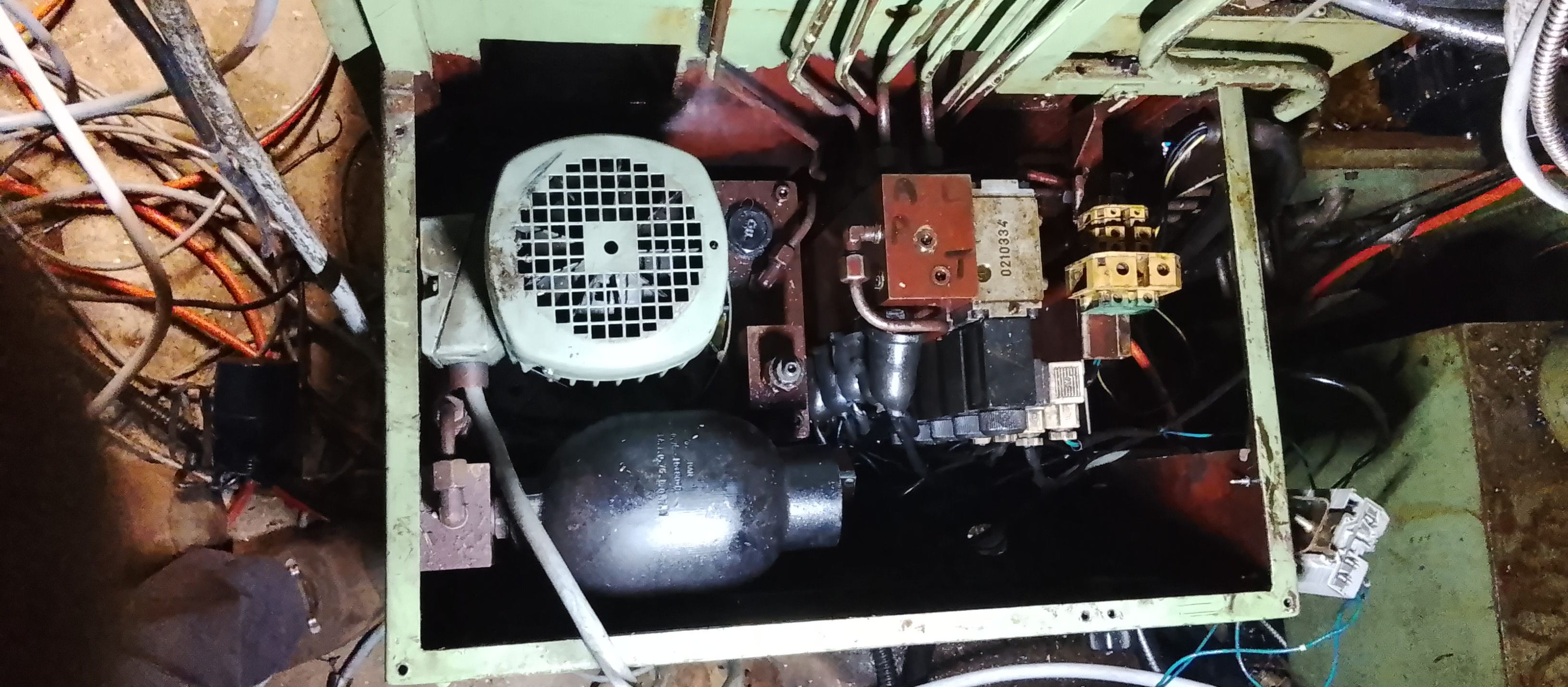
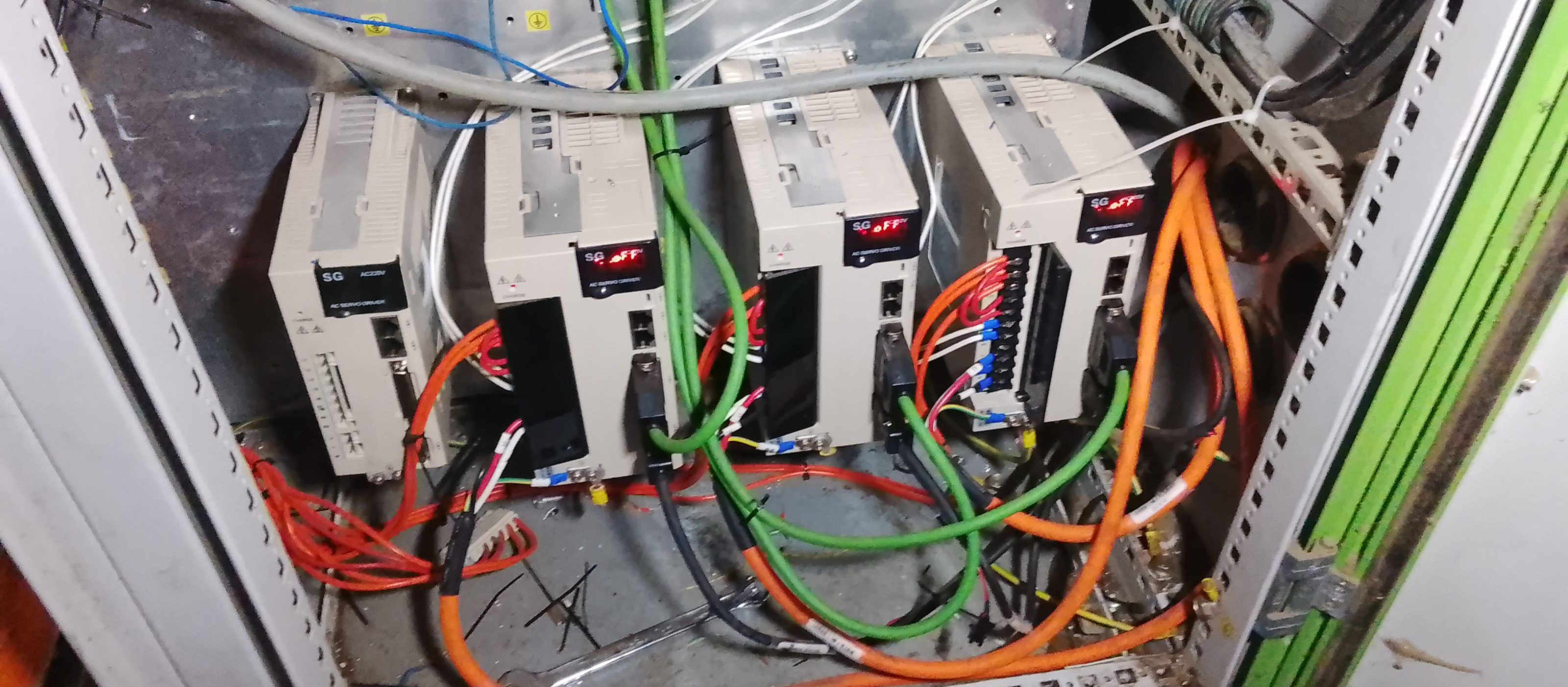
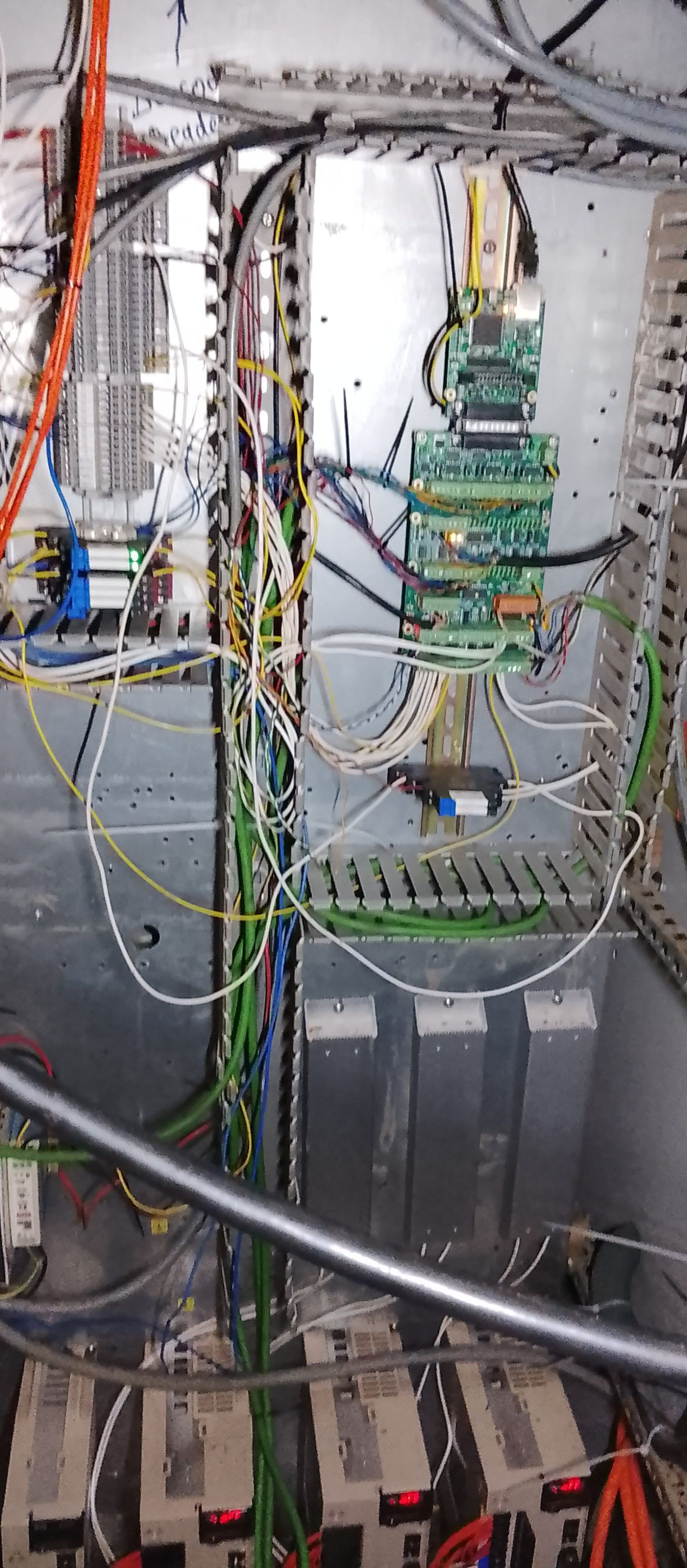
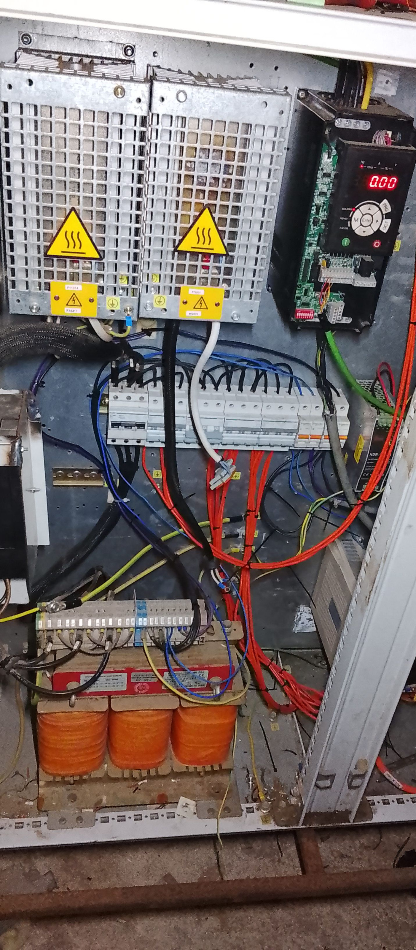
 So pretty happy all in all would like to fix the index enable issue in the future but for now it's working fine. this is a 40 year old machine and weighs 12 ton. and when i got it the backlash was 0.40mm. I replaced all the thrust bearings and changed from reduction gearbox to a nice mazak flexible coupling and direct drive. The timing belt was T8 timing belt so not even HTD profile which has more backlash which didn't help. The FIL factory actually got the location of the Z axis 2nd ballscrew mount out by 2.4mm which i was shocked by. i double checked measuring against the slideways at the top and bottom of the screw and yeah it was out 2.4mm from factory! so that is why all the thrust bearings were stuffed. anyway just about to get it running into production. this machine will be running like 16 hrs a day shortly probably.Lastly just have some photos of the control cabinet. I wasn’t sure if I would post these. My wiring is never that clean and currently machine is mid progress so wires everywhere. But enjoy The system has 7i92m 7i77 7i84 mesa cards And yuhai Chinese servo drives 3.5kwPlus 11kw spindle vfd. Which I might get another one for the horizontal spindle.The machine was actually working when I got it. But it took me 30 min to just work out how to turn the 40 year old software on. And it had old dc brushed drives and 40 year old servo motors and I just didn’t want to have to deal with it. I run a machine shop in New Zealand full time and work for a lot of larger customers making money and time is money.. so definitely not a hobby here anymore. we have like 60 tons of CNC gear here (7 machines currently) all running linuxcnc apart from one fagor controlled lathe i haven't bothered yet. So I just didn’t want to deal with issues. I want a machine that just works for the next 10 years. I have machines that have worked flawlessly for 6 years so far and keen to run the same system. You turn it on and make parts. That’s it.
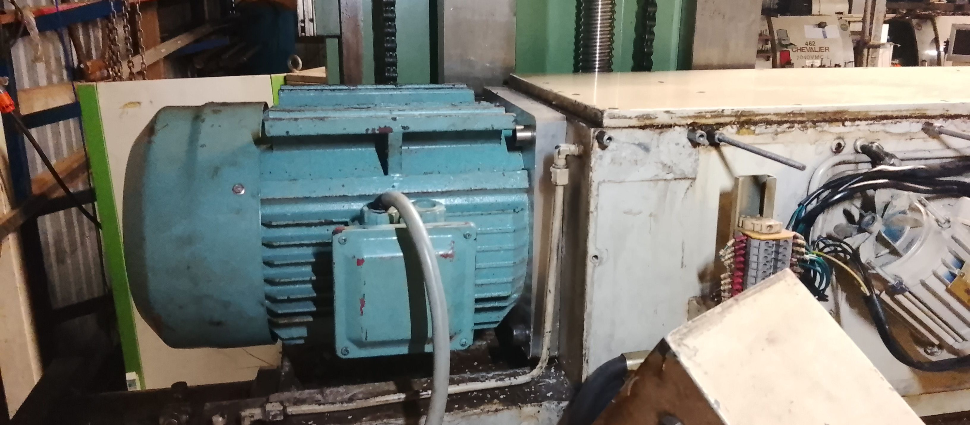
new spindle motor i fitted. nothing fancy had it laying around.
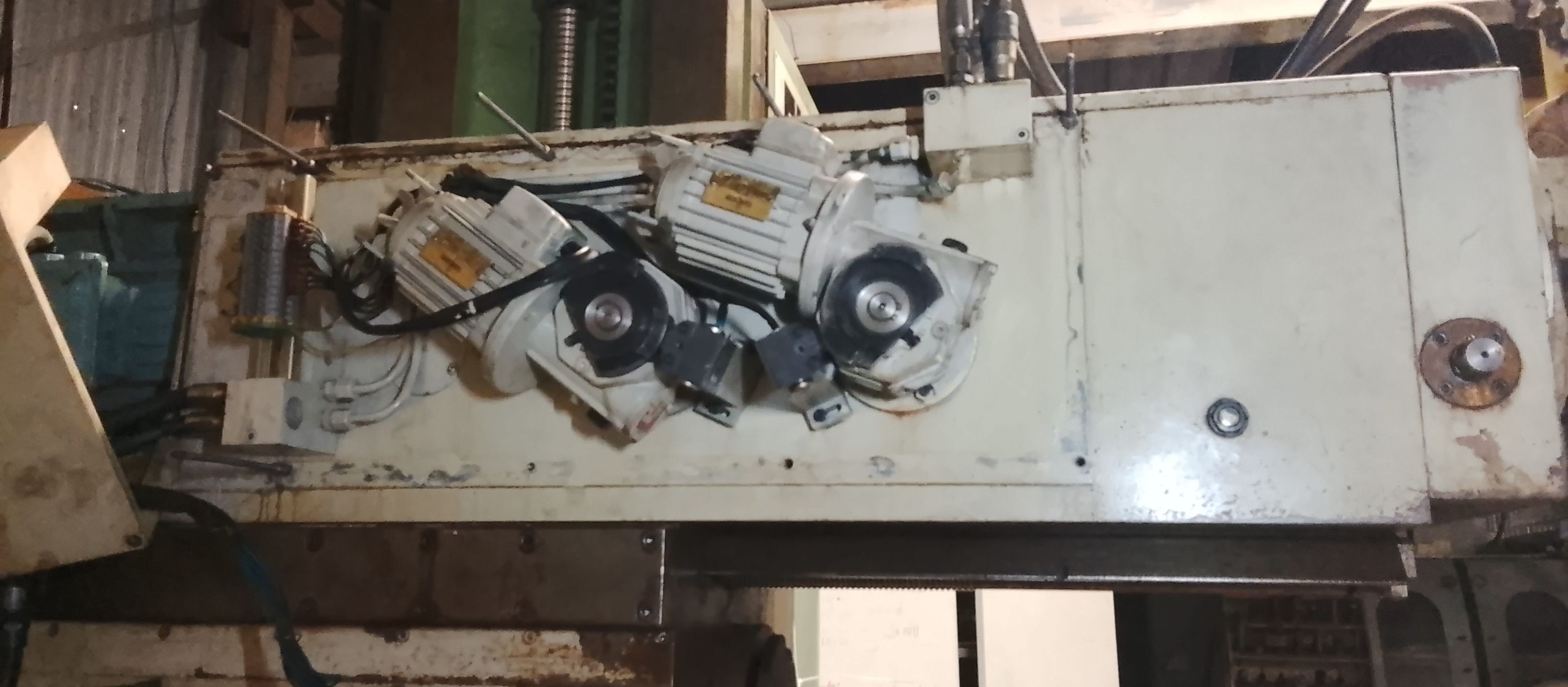
and lastly spindle gearchange setup. you can buy a 400watt VFD for like 30 usd on aliexpress currently. so i use those instead of contactors. so i get nice overloads variable speed. electrical braking and easy wiring all in one. plus cheaper:)
It has a accumulator so what you do is you turn the pump on and then wait until the pressure switch triggers and turn pump off. This machine only needs oil when toolchanging so it’s a great idea really and allows me to not need a pump running all the time. Once I worked out how it worked it is great and very easy to setup in classic ladder
next thing i need to talk about is how i am handling homing currently
this is just copied and pasted from the email user list. great place to get fast answers to questions btw
This email address is being protected from spambots. You need JavaScript enabled to view it.
Hey guysthanks for the replies the homing is a interesting issue I had a bit of a play and made a copy of my config that i hacked. What i found was that if i combined my original 2 PID loops into 1 loop and used the scale for position and used the motor velocity on encoder for velocity all in one PID then homing to index enable worked perfectly. but doing it that way the motor tuning was not as good. backlash is a constant of 0.1mm and the motor just jumped across that backlash whenever it moved. in practice that meant that the absolute scale position hovered by +-0.01 or so. this was not bad and totally usable. If i had done this option first i would have called it good and just used it. but the movement was much louder and less smooth than the two PID loops which get run through a sum component. As the original two PID loops was much much smoother, it was perfect and once i come to a stop the drive rapids to within 0.01 or 0.02 and then creeps the last 0.02mm (using the integral value which takes about a second) and ends up in the right place within 0.005mm or less. basically perfect every time with no dithering. It is now my most accurate machine. and really nice also the homing when homing I home all axis at the same time. X and Y get homed to index enable like normal. and the Z value i trick the home switch by checking the joint state. How this works is the Joint2 switch state goes form 7 when searching for switch the first time to 12 when latching on to switch slowly the second time so in classic ladder i set up two compare functions that basically choose whether to listen to the main home switch or the z axis motor encoder Z index pulse. (this is different to the index enable pulse and this is possible to miss when only checking in software not hardware. but at a slow speed i haven't found any issues yet, and when testing with a dial indicator i can't see any changes between homing. I can rehome linuxcnc up the top of the travel beside the home switch and then rapid down to the table which is about 1m away and the dial indicator is definitely within 0.01 each time. i can't really see any movement on it.
photos show the classic ladder stuff might help someone
new spindle motor i fitted. nothing fancy had it laying around.
and lastly spindle gearchange setup. you can buy a 400watt VFD for like 30 usd on aliexpress currently. so i use those instead of contactors. so i get nice overloads variable speed. electrical braking and easy wiring all in one. plus cheaper:)
- motionmasterupgrade
- motionmasterupgrade
16 Apr 2026 15:19
Columbo 7.5hp spindle was created by motionmasterupgrade
Columbo 7.5hp spindle
Category: User Exchange
Hey, folks here literally saved my ass from a disaster so I'm passing it on.
I have a 7.5hp old Columbo spindle that I know little about besides:
(a) Resistance is 1.8ohm consistent across all 3 windings.
(b) Its from 1994ish, and serviced in 2004.
(c) Manual change, and the mechanism to hold the spindle works.
(d) CAT40, insides look good, threads look good.
(e) 18000rpm (I think)
(f) About 80 freedom weight units (says so on the maintenance invoice from 2004).
Free.
You pay shipping. Its located in southern New Hampshire in Freedomland.
I will post runout or vibration numbers once I get set up to measure everything.
Do request any info you need, and I'll update it here as I measure stuff.
I'm trying to set up linuxcnc on an old motion master bridge. Reusing the brushed servos and 4 amp. drives. Adding 4 pulse train Yaskawa servos/drives (this is the upgrade) to swivel head and rotaries. I'd very much appreciate someone willing to take a few calls and guide me along so I can get help or quick opinions when in a pinch. I've so far managed to covert a 480V machine to 220V.
Something I'd love is a 7i77u board (just borrow it for a few weeks if you have one to spare). I just don't know enough to understand if I can use 7i77 boards that are immediately available. That's my immediate next step.
They are out of stock and I'm hard up for time. Wife gave me permission to start a project with a machine that is the size of a room, and then, a few weeks later, tells me the whole family is moving to a place that not much bigger than the room the machine is filling up. FML.
Make stuff and prosper.
- reboots
- reboots
04 Apr 2026 22:05
Replied by reboots on topic Spindle delay
Spindle delay
Category: Basic Configuration
I just wanted to register that this solved the same issue for me on 2.9.7. There are older solutions on the forum, for example "
Automatic pause when spindle is started
" from 2015, but they don't reflect current pin/signal names. Modified default spindle control HAL section below, two lines commented out and six more required.
My spindle VFD is connected as follows for simple "run" operation with no feedback:
# ---setup spindle control signals---

net spindle-vel-cmd-rps        <=  spindle.0.speed-out-rps
net spindle-vel-cmd-rps-abs    <=  spindle.0.speed-out-rps-abs
net spindle-vel-cmd-rpm        <=  spindle.0.speed-out
net spindle-vel-cmd-rpm-abs    <=  spindle.0.speed-out-abs
net spindle-enable             <=  spindle.0.on
net spindle-cw                 <=  spindle.0.forward
net spindle-ccw                <=  spindle.0.reverse
net spindle-brake              <=  spindle.0.brake
net spindle-revs               =>  spindle.0.revs
##net spindle-at-speed           =>  spindle.0.at-speed
net spindle-vel-fb-rps         =>  spindle.0.speed-in
net spindle-index-enable      <=>  spindle.0.index-enable

# ---Setup spindle at speed signals---

##sets spindle-at-speed true

# 5-second spindle ramp delay
loadrt timedelay count=1
addf timedelay.0 servo-thread
setp timedelay.0.on-delay 5
net spindle-enable => timedelay.0.in
net spindle-timer <= timedelay.0.out
net spindle-timer => spindle.0.at-speed
My spindle VFD is connected as follows for simple "run" operation with no feedback:
net spindle-enable => hm2_5i25.0.7i77.0.0.output-00- tommylight

31 Mar 2026 19:51
Replied by tommylight on topic MotionMaster Upgrade
MotionMaster Upgrade
Category: General LinuxCNC Questions
I might not be the best person to reply to this as i absolutely enjoy retrofitting and bringing back to life old machines, so i may be a bit on the "trigger happy" side, but:
-i would try to use the existing drives and motors and VFD/spindle
-seems like those are analog drives, so a Mesa 7i97T would do perfectly fine if you can find one, if not a 7i92T with 7i77 is the same thing, or if those are also scarce a 7i96S with 7i85 and 7i83 should do the same job.
-if you still want to replace the drives, you have two choices in general: EtherCAT or Mesa with normal step/dir or analog servos (do not bother to look at steppers and close loop steppers)
-You will be bombarded by others to choose EtherCAT, i am still avoiding them due to some fuzzy communication issues, but i will test them for sure the fist chance i get.
-For the Mesa/new drives, i would look for "position and velocity" mode drives (analog +-10V and step/dir) and also with encoder outputs (all have encoder inputs or absolute encoders, usually serial ones) so the loop can be closed in LinuxCNC with both types of control, makes life easier during use. Given the choice between analog and step/dir, choose step/dir.
- grossm5000
- grossm5000
28 Mar 2026 16:53
Replied by grossm5000 on topic Differential encoder hard crashes the PC MESA7i77
Differential encoder hard crashes the PC MESA7i77
Category: Driver Boards
No, I was just setting up. I have a couple toggle switches working on gpio but that’s it. I was just getting excited I could see it talking through halshow. No servo/spindle drivers yet.
I figured the MPGs should have been the next easiest thing to do
I figured the MPGs should have been the next easiest thing to do
- LucaGiorcelli
- LucaGiorcelli
10 Mar 2026 21:31
Machine choice for composite panel CNC + probe-driven XY/Z G-code compensation was created by LucaGiorcelli
Machine choice for composite panel CNC + probe-driven XY/Z G-code compensation
Category: Milling Machines
Hi all,
I'm planning a gantry router build for machining composite panels into cabinet components. Looking for advice on machine choice and stack.
Material
- Sandwich panels: 1mm aluminium skins on both faces, polyurethane foam core
- Total thickness: ~60mm nominal, but varies ±1mm across a batch
- Panel size: up to 1500x3000mm
Parts and operations

- Cutting outlines
- Pockets and step joints on panel face
- V-scoring the aluminium skin to create precise fold lines (score-and-fold)
These operations require multiple tools in a single job (end mills for pockets and joints, V-bit for scoring), so automatic tool change (ATC) is a hard requirement.
The step joints are the critical operation: they create mechanical overlap between mating panels so cabinets assemble with tight joints. A 1mm thickness variation in the stock translates directly into a gap.
Workflow
probing → generate Z map → process map (Python) → adjust G-code geometry (XY and Z) → send corrected G-code → machining
- Fusion 360 CAM produces nominal G-code
- Before cutting, I probe a grid of Z points across the panel surface
- A Python script reads the probe map and rewrites the G-code: step depths and joint profiles are adjusted to the actual measured local thickness — for both the panel being cut and its mating counterpart
- This is not just Z surface compensation: XY profiles are modified based on the probe map so that mating joints match regardless of thickness variation
Why LinuxCNC
- Workflow already tested with LinuxCNC + MESA cards (7i96/7i77) on an entry level router.
- Plan to use the Python socket interface for probe data collection and G-code rewriting — tight integration between probing and post-processing is central to the workflow
My questions
1. Are there manufacturers selling new gantry routers with these specs who ship with LinuxCNC, or sell mechanics separately from the controller?
- Working envelope: ~1600x3200mm
- HF spindle: 18k+ RPM
- Integrated vacuum table with independently switchable zones
- ATC (tool magazine or rack)
- Probe input
2. For a retrofit path: which used industrial gantry platforms have the best LinuxCNC community experience?
- Main concerns: ATC integration and vacuum zone management via MESA I/O
3. Any experience with probe-map-driven G-code modification beyond simple Z surface mapping?
- Currently planning G38.x + Python
- Is there a better pattern for this use case?
Thanks
I'm planning a gantry router build for machining composite panels into cabinet components. Looking for advice on machine choice and stack.
Material
- Sandwich panels: 1mm aluminium skins on both faces, polyurethane foam core
- Total thickness: ~60mm nominal, but varies ±1mm across a batch
- Panel size: up to 1500x3000mm
Parts and operations
- Cutting outlines
- Pockets and step joints on panel face
- V-scoring the aluminium skin to create precise fold lines (score-and-fold)
These operations require multiple tools in a single job (end mills for pockets and joints, V-bit for scoring), so automatic tool change (ATC) is a hard requirement.
The step joints are the critical operation: they create mechanical overlap between mating panels so cabinets assemble with tight joints. A 1mm thickness variation in the stock translates directly into a gap.
Workflow
probing → generate Z map → process map (Python) → adjust G-code geometry (XY and Z) → send corrected G-code → machining
- Fusion 360 CAM produces nominal G-code
- Before cutting, I probe a grid of Z points across the panel surface
- A Python script reads the probe map and rewrites the G-code: step depths and joint profiles are adjusted to the actual measured local thickness — for both the panel being cut and its mating counterpart
- This is not just Z surface compensation: XY profiles are modified based on the probe map so that mating joints match regardless of thickness variation
Why LinuxCNC
- Workflow already tested with LinuxCNC + MESA cards (7i96/7i77) on an entry level router.
- Plan to use the Python socket interface for probe data collection and G-code rewriting — tight integration between probing and post-processing is central to the workflow
My questions
1. Are there manufacturers selling new gantry routers with these specs who ship with LinuxCNC, or sell mechanics separately from the controller?
- Working envelope: ~1600x3200mm
- HF spindle: 18k+ RPM
- Integrated vacuum table with independently switchable zones
- ATC (tool magazine or rack)
- Probe input
2. For a retrofit path: which used industrial gantry platforms have the best LinuxCNC community experience?
- Main concerns: ATC integration and vacuum zone management via MESA I/O
3. Any experience with probe-map-driven G-code modification beyond simple Z surface mapping?
- Currently planning G38.x + Python
- Is there a better pattern for this use case?
Thanks
- kb0thn
- kb0thn
10 Mar 2026 11:31
Replied by kb0thn on topic Laser power scaling based on speed and direction
Laser power scaling based on speed and direction
Category: HAL Examples
Much thanks to iforce2d for this implementation and write-up. I just deployed a slightly tweaked version of it to my 4x10' router that has a 40 watt laser as second spindle.
I had to modify the component to force zero power output when there was no motion. It looks like the original first line of code can result in a NaN and then my machine was ending up with a 50% PWM output in that state. So I force NaN to zero. That worked okay in my testing at a fixed z height. But when running an actual program I retract Z between parts and I was finding that Z only motion was leaving the laser stuck on. So now I also force zero power output when X and Y motion are essentially zero.
I use a bunch of MESA cards including a 7I77 and a 7I76. And then some additional IO boards linked via serial. I never figured out how to get a hardware PWM output. So I am using software PWM for driving the laser. Here are the relevant sections of my custom.hal file showing how it all goes together:
I had to modify the component to force zero power output when there was no motion. It looks like the original first line of code can result in a NaN and then my machine was ending up with a 50% PWM output in that state. So I force NaN to zero. That worked okay in my testing at a fixed z height. But when running an actual program I retract Z between parts and I was finding that Z only motion was leaving the laser stuck on. So now I also force zero power output when X and Y motion are essentially zero.
component aprs_laserreg "";

pin in   float inpower    "Desired laser power at constant speed";
pin in   float reqspd    "Requested speed, connect to motion.requested-vel";
pin in   float curspd    "Current speed, connect to motion.current-vel";
pin in   float velx    "Current speed x component, connect to joint.0.vel-cmd";
pin in   float vely    "Current speed y component, connect to joint.1.vel-cmd";
pin in   float velz    "Current speed y component, connect to joint.1.vel-cmd";
pin in   float share    "Fraction of power given to pure Y movement, eg. 0.6";
pin out  float outpower "Scaled output laser power";

function _ fp "Update the laser power";

license "GPL";

;;

#include <math.h>

FUNCTION(_) {
	outpower = inpower * (curspd / reqspd);

	float angle = atan2(fabs(velx), fabs(vely));  // angle away from y in radians
	float horz = angle / (0.5*M_PI);          // 1 when moving perfectly along x axis
	outpower *= share + (1-share) * horz;

	if ( outpower > inpower )
		outpower = inpower;
	if ( outpower > 100 )
		outpower = 100;
	if ( ( fabs(velx)<1e-6 && fabs(vely)<1e-6 ) || isnan(outpower) || outpower < 0 )
		outpower = 0;

}
I use a bunch of MESA cards including a 7I77 and a 7I76. And then some additional IO boards linked via serial. I never figured out how to get a hardware PWM output. So I am using software PWM for driving the laser. Here are the relevant sections of my custom.hal file showing how it all goes together:
# laser engraver
# software PWM
loadrt pwmgen output_type=0
addf pwmgen.update      servo-thread
addf pwmgen.make-pulses servo-thread # should be base-thread
setp pwmgen.0.enable TRUE
setp pwmgen.0.scale 65535

# based on https://forum.linuxcnc.org/47-hal-examples/54073-laser-power-scaling-based-on-speed-and-direction
loadrt lincurve personality=2
loadrt aprs_laserreg # for some reason the component gets renamed to aprs-laserreg (ie changes _ to -)

addf lincurve.0         servo-thread
addf aprs-laserreg.0    servo-thread # I don't seem to have a base-thread. I think because it is MESA


# Laser power mapping (0-100 -> 0-65535)
setp lincurve.0.x-val-00 0
setp lincurve.0.y-val-00 0

setp lincurve.0.x-val-01 100
setp lincurve.0.y-val-01 65535

net laser-requested-speed      motion.requested-vel    => aprs-laserreg.0.reqspd
net laser-current-speed        motion.current-vel      => aprs-laserreg.0.curspd
net laser-velx                 joint.0.vel-cmd         => aprs-laserreg.0.velx
net laser-vely                 joint.1.vel-cmd         => aprs-laserreg.0.vely
net laser-velz                 joint.2.vel-cmd         => aprs-laserreg.0.velz
setp aprs-laserreg.0.share     1.0

net laser-percent              spindle.1.speed-out      => aprs-laserreg.0.inpower
net laser-regulated-percent    aprs-laserreg.0.outpower => lincurve.0.in
net laser-65535                lincurve.0.out           => pwmgen.0.value
net laser-pwm                  pwmgen.0.pwm             => optimat_o_laser_engraver_pwm

# second spindle we will always consider to be at speed
net laser-at-speed => spindle.1.at-speed
sets laser-at-speed true- GDTH

06 Mar 2026 11:11
Rover 336 retrofit – horizontal drills and tool offsets in LinuxCNC was created by GDTH
Rover 336 retrofit – horizontal drills and tool offsets in LinuxCNC
Category: Advanced Configuration
Hello,I am currently retrofitting a Biesse Rover 336 with LinuxCNC.The machine is controlled with a Mesa 7i77, and I am using EtherCAT modules distributed throughout the machine for the I/O.Originally the machine had a Control Techniques Unidrive VFD, but I was unable to change the required parameters, so I replaced it with a Danfoss VFD, which is now working well.At this point the machine is mostly operational:
Error: Function 'positionABC' can only be used with multi-axis machine configurations.
Error at line: 2040
Error in operation: 'Drill2'I suspect this may be related to how I defined the horizontal drilling operation.Is there a recommended way to program horizontal drilling for drill banks in Fusion when targeting LinuxCNC?Any advice from people who have implemented drill banks or horizontal drills on router-style machines would be very helpful.Thanks!
- Homing works
- XYZ motion works
- Spindle runs correctly
- The toolchanger sequence is mostly prepared
- Toolchanger: 7 tools
- Vertical drills: ~25
- Horizontal drill (X axis): 1
- Horizontal drills (Y axis): 3
- Tools 1–7 → spindle toolchanger
- Tools 101–130 → drill bank (fixed tools)
- Store the offsets in the tool table (like normal tools)
- Apply the offsets inside the M6 tool change routine, since these drills are fixed and it may reduce the chance of mistakes.
Error: Function 'positionABC' can only be used with multi-axis machine configurations.
Error at line: 2040
Error in operation: 'Drill2'I suspect this may be related to how I defined the horizontal drilling operation.Is there a recommended way to program horizontal drilling for drill banks in Fusion when targeting LinuxCNC?Any advice from people who have implemented drill banks or horizontal drills on router-style machines would be very helpful.Thanks!
- okielaxplyr
- okielaxplyr
27 Feb 2026 01:20
7I77D over heat was created by okielaxplyr
7I77D over heat
Category: Driver Boards
I am using a optocoupler (from amazon) between my 7i77D output and a solenoid valve for a spindle break in the sinking configuration, the output is over-temperature faulting for some reason.
using TB8 OUTPUT0. Field voltage is 24Vdc and driving the relay with the same 24 power supply.
I set up the opto relay on the bench and it only draws 2.2ma on the input in low position.
I'm kind of at a loss, the manual says the outputs can take up to 350ma.
Please advise
John V.
using TB8 OUTPUT0. Field voltage is 24Vdc and driving the relay with the same 24 power supply.
I set up the opto relay on the bench and it only draws 2.2ma on the input in low position.
I'm kind of at a loss, the manual says the outputs can take up to 350ma.
Please advise
John V.
- NT4Boy
- NT4Boy
19 Feb 2026 17:22
Replied by NT4Boy on topic HURCO KMB-1 Control Update
HURCO KMB-1 Control Update
Category: Milling Machines
I've ended up fighting the hal loader.
#
# M19 ORIENT – single driver / multi‑sink form
#
loadrt orient count=1
addf orient.0 servo-thread
loadrt pid names=pid.o
addf pid.o.do-pid-calcs servo-thread
loadrt mux2 count=1
addf mux2.0 servo-thread
loadrt or2 count=1
addf or2.0 servo-thread
# --- Orient PID tuning ---
setp pid.o.Pgain 0.05
setp pid.o.Igain 0.0005
setp pid.o.Dgain 0.0002
setp pid.o.maxoutput 60
setp pid.o.error-previous-target true
setp orient.0.tolerance 0.05
setp orient.0.angle 0
# --- One signal name, declared once and fanned out ---
net orient-bit spindle.0.orient => orient.0.enable
net orient-bit => or2.0.in1
net orient-bit => mux2.0.sel
# separate signal drives the encoder’s index enable input
net orient-arm-index orient-bit => hm2_7i92.0.encoder.05.index-enable
# --- Run enable OR gate ---
net run-enable or2.0.out => hm2_7i92.0.7i77.0.1.spinena
net spindle-enable => or2.0.in0
# --- Orient angle / feedback wiring ---
net orient-angle spindle.0.orient-angle => orient.0.angle
net spindle-revs hm2_7i92.0.encoder.05.position => orient.0.position
# --- Orient PID loop ---
net orient-cmd orient.0.command => pid.o.command
net orient-fb hm2_7i92.0.encoder.05.velocity-rpm => pid.o.feedback
net orient-out pid.o.output => mux2.0.in1
# --- Normal spindle path and output switch ---
net spindle-output pid.s.output => mux2.0.in0
net spindle-vfd-out mux2.0.out => hm2_7i92.0.7i77.0.1.analogout5
# --- Completion flag back to controller ---
net orient-done orient.0.is-oriented => spindle.0.is-oriented
#Error in file ./spindlecontrol.hal:
# Pin 'orient-bit' does not exist
#Shutting down and cleaning up LinuxCNC…
#
# M19 ORIENT – single driver / multi‑sink form
#
loadrt orient count=1
addf orient.0 servo-thread
loadrt pid names=pid.o
addf pid.o.do-pid-calcs servo-thread
loadrt mux2 count=1
addf mux2.0 servo-thread
loadrt or2 count=1
addf or2.0 servo-thread
# --- Orient PID tuning ---
setp pid.o.Pgain 0.05
setp pid.o.Igain 0.0005
setp pid.o.Dgain 0.0002
setp pid.o.maxoutput 60
setp pid.o.error-previous-target true
setp orient.0.tolerance 0.05
setp orient.0.angle 0
# --- One signal name, declared once and fanned out ---
net orient-bit spindle.0.orient => orient.0.enable
net orient-bit => or2.0.in1
net orient-bit => mux2.0.sel
# separate signal drives the encoder’s index enable input
net orient-arm-index orient-bit => hm2_7i92.0.encoder.05.index-enable
# --- Run enable OR gate ---
net run-enable or2.0.out => hm2_7i92.0.7i77.0.1.spinena
net spindle-enable => or2.0.in0
# --- Orient angle / feedback wiring ---
net orient-angle spindle.0.orient-angle => orient.0.angle
net spindle-revs hm2_7i92.0.encoder.05.position => orient.0.position
# --- Orient PID loop ---
net orient-cmd orient.0.command => pid.o.command
net orient-fb hm2_7i92.0.encoder.05.velocity-rpm => pid.o.feedback
net orient-out pid.o.output => mux2.0.in1
# --- Normal spindle path and output switch ---
net spindle-output pid.s.output => mux2.0.in0
net spindle-vfd-out mux2.0.out => hm2_7i92.0.7i77.0.1.analogout5
# --- Completion flag back to controller ---
net orient-done orient.0.is-oriented => spindle.0.is-oriented
#Error in file ./spindlecontrol.hal:
# Pin 'orient-bit' does not exist
#Shutting down and cleaning up LinuxCNC…
- NT4Boy
- NT4Boy
17 Feb 2026 13:50
Replied by NT4Boy on topic HURCO KMB-1 Control Update
HURCO KMB-1 Control Update
Category: Milling Machines
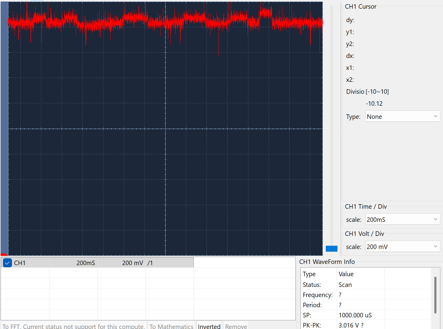
I replaced the spindle motor VFD, three phase outpout and the speed signal is 0-10v.
I notice that the speed varies in a random way and at say 1000 rpm, I get steps of 15 to 30 plus and minus.
The fuzzy line is an oscilloscope trace of the analogout5 pin on the 7i77.
The lower halscope trace is the same pin also nominally at 1000, offset and magnified to show what I can hear.
I have started the spindle using MDI with M3 S1000.
Any ideas what maye be going on?
Time to create page: 0.744 seconds