Search Results (Searched for: stepper spindle)
- Todd Zuercher

DIY CNC
Category: Milling Machines
There are even some special things that you can do using a parallel port that you can't really easily do with Mesa cards and hardware stepgens. I had a machine that I retrofitted to Linuxcnc, that I wanted to keep the ability to plug in and reuse the original control. It had it's own driver box for the step motors and used individual commands to directly trigger the stepper coils rather than traditional step/dir commands. I was able to directly replicate those signals using Linuxcnc's software stepgen and output them to a parallel port.
- NWE

DIY CNC 2
Category: Milling Machines
How many stepper drives? If 3, then we're looking at 4 amps per motor * 3 = 12 amps total. Your stepper drives will draw less than that. Now, cheap PSUs tend to be overly optimistic with their current rating. I think your PSUs are easily sized double what these specs require. Which I think is a good plan. Go for it. I would buy that.So based upon what I'm using you don't think I need to swap out for a different PSU that has said protections?
Your twisted pair cable looks great. I was just coming back with a suggestion 18 Gauge 4 Conductor Shielded when I noticed your post.
- dst
- dst
Prvomajska G301 Milling machine converting to CNC
Category: Milling Machines
More than10 years ago (at that time i just started my studies) my father found a great milling machine in a scrapyard, Prvomajska G301 D1 manufactured in 1973 , the machine seems to be almost not used at all, unfortunately it was subject to weather changes and most of the axis were locked up by rust, its spindle motor and holding bracket broken off and x axis gearbox with motor broken off. Back when he brought it home we started to disassemble, we removed some parts from its quill and then life happened we left it on the field covered with plastic sheets as there was no more space on the workshop.
Recently we removed some things from the shop and got some place for the mill and we placed it inside, past week we were working very hard to clean up the rest of the machine and mount it back, so far the worst part is that its spindle bearing are quite rusty and once we get the rest sorted out will have to be replaced (altho, i still dont know where we could find it).
Attached are images of before and after cleanup and a picture of a machine we found online.
Couple of decisions weve come up with so far regarding the mechanical parts are as following:
Z-Axis: The Z-Axis has 36mm trapezoidal screw moved through bevel gears from the handle and the nut is bolted on the base of the machine offset by an iron piece, maybe can be seen from a picture when the saddle traverse was removed. Since we couldnt find a neat way to put a ball screw, also, were assuming the ball screw having less friction forces the z axis will just fall down, weve decided to leave the original screw and return back to it if we find any issue later on, following This Old Tony's conversion of his Maho and leaving its Z axis with trapezoidal screw, we're expecting the same...
X/Y-Axis: Both have 28mm trapeziodal screws with anti-backlash nut with pitch of 5mm. The nuts hole on the casting for both sides is 40mm which to our research matches the 25mm ballscrew so it is more or less the driving factor to chose 25mm ballscrews.
Issue #0: Throughout this project we always find it challenging to transport anything to place where we live due to some political issues and locally there is no store that sells parts. One of the solution we've found is a middleman in Germany that transports things to here so more or less we always have to check for delivery to Germany and goods that arent subject to VAT...
Question #1: We plan to travel to a nearby country that has ballscrews however im a little bit confused by Dynamic load rating and Static load rating related to price. A low price offers C(dyn) ~ 1100kgf and C(0) ~ 2700kgf, while a 5 times the low price C(dyn) ~ 1700kgf and C(0) ~ 5000kgf, but a 6 times the low price we can get a C(dyn) ~ 14900kgf and C(0) ~ 41500kgf... I'd appreciate a suggestion if going with the low price option is sufficient, as the 5 times the price seems to not gain much for the added cost and the last option seems like a straight up overkill..
Question #2: For the Motors to drive the axis of the machine, were planning to place stepperonline servo motors rated at 1kW ( link ) but interestingly they seem to have EtherCAT servos as well so im kinda on a edge here.. I was originally planning to go with mesa cards prior to seeing the EtherCAT options, but now i kinda dont mind the added cost for EtherCAT, however, my father hopes to use the machine as a manual mill but he isnt very technophile so we will have to add quite some buttons and dials rather than use the keyboard/mouse to control the machine manually and for this we will need some IO, so, is there any EtherCAT IO that i can daisy chain to the system? I have no experience with EtherCAT so i dont know what im getting into... does LinuxCNC need to support the mentioned drive? Do we have to expect support from the manufacturer for the application? Is it doable?
Question #3: If i was to go with normal drives, i cant really decide on the loop's of the system and therefore the cards. I dont have any experience with Mesa cards, but i do have some experiences with parallel port LinuxCNC and Raspberry GPIO LinuxCNC. Should i go straight to position loop on mesa cards and velocity loop on the drive (hence analog mesa cards) or shall i take it slow and get a step/dir card and later on get an analog card if im happy with it?
Question #3.1:This leads to does Mesa official store shipment to Germany include VAT and complicated transportation or is it simple drop off?
Question #3.2: Can you suggest a good card match up for 4 Axis movement + Spindle + Lots of IO for control panel?
Question #4: Since Servos offer modbus and you can read the position of its absolute encoder im assuming that you can skip the homing procedures on LinunxCNC and fetch position from drives directly, am i correct?
Question #5: How important is spindle encoder for a milling machine? I cant seem to find a proper place to seat it...
Any suggestion, question or comment welcomed!
Thanks in advance!
- Logthor
- Logthor
DIY CNC 2
Category: Milling Machines
I meant to say steppers my mind just slipped I guess.Nomenclature nitpick: Unless you've got encoders on there, those are stepper motors, not servos. And even steppers + encoders are typically referred to as "closed-loop steppers", not servos.
Noted. The geckodrives are a bit too expensive for me to consider. If you have an recommendations for a good PSU I'm all ears. Additionally, regarding the drivers I have picked out, I assume it is RMS current right in that documentation?PSU: If you're going to use a switch-mode PSU, make sure you get a big (uF rating, voltage rating) capacitor to put on it. Motors dump energy into the PSU on deceleration, which can lead to voltage spikes and blown stepper drives and/or PSU. A toroidal/transformer based supply is often recommended instead for this reason.
If I use a CAT6a cable will the shielding on it provide enough insulation to avoid being influenced by EMI?Wire: You may want multi-conductor wire. If that's for the steppers, 4-conductor would be good. Running 4 separate wires to each motor seems unnecessarily obnoxious.
I'm probably just going to use a spray bottle with coolant for the mean time. Not sure what you mean by MPG, the machine I have has manual lead screw handles built in to jog it. I'm going to control the spindle with the 7I96S and hope it spins at the speeds I want while cutting. Touch probe's seem expensive unless there is a cheap one on amazon. Regarding a toolsetter, buttons, and rotary axis, all that seems quite far away atm. I'm going to worry about making it work first.-Coolant/air blast control
-MPG
-Spindle encoder
-Touch probe
-Toolsetter
-Hardware feed hold/single-step/pause/resume/etc. buttons
-Rotary axis
- dbtayl
- dbtayl
DIY CNC 2
Category: Milling Machines
PSU: If you're going to use a switch-mode PSU, make sure you get a big (uF rating, voltage rating) capacitor to put on it. Motors dump energy into the PSU on deceleration, which can lead to voltage spikes and blown stepper drives and/or PSU. A toroidal/transformer based supply is often recommended instead for this reason.
This may also be useful: www.geckodrive.com/support/power-supply-basics/
Wire: You may want multi-conductor wire. If that's for the steppers, 4-conductor would be good. Running 4 separate wires to each motor seems unnecessarily obnoxious.
Missing from your list: buttons, switches, fans, terminal blocks, enclosure, mounting hardware, connectors. Specifically, you'll probably want to put your parts in a box of some kind, and at the very least an e-stop is a good idea. Generally you want that wired such that it hard-cuts power to the motors+spindle of the machine or otherwise renders it in a safe state.
Drawing out everything you'll use and the connections between them can help identify gaps- eg, making sure you have enough terminal blocks. It's shockingly easy to run out of those. Ditto for enclosure space- a little planning goes a long way there, and also getting a bigger enclosure than you think you need.
Finally: I'm not familiar with all the mesa offerings (I've got a 7i76e on my mill, IIRC), but try to think about what you might want in the future and then you can decide whether it's worth buying something with spare I/Os to support it now or accepting you may need to upgrade the card later to add things. Things you might consider:
-Coolant/air blast control
-MPG
-Spindle encoder
-Touch probe
-Toolsetter
-Hardware feed hold/single-step/pause/resume/etc. buttons
-Rotary axis
IIRC you've got a Taig, and IIRC those use ER collets or equivalent... my experience is re-zeroing tools with ER collets gets old fast. I more than once trashed a tool and/or workpiece forgetting to do so... a toolsetter IMO would be worth planning for.
- Zipdodar
- Zipdodar
using linuxcnc on a raspberry pi to control a boxford 250pc lathe
Category: General LinuxCNC Questions
I just purchased a boxford 250pc lathe in a hardely used immaculate condition; however, as per the norm, it has no brain and the internal electronics, although pretty much unused, will be changed over to new stuff so I eliminate any issues and get going properly first time.
I will then likely use all the removed bits for other projects.
- controllers
At the moment, I am considering LinuxCNC, Mach 3/4, poss arduino, and Centroid Acorn
So can anyone advise if LinuxCNC on a Raspberry Pi will be powerful enough and good enough to use on a Boxford 250PC lathe with 2-axis, a tool changer, homing limit switches, spindle encoder with z values for threading, spindle speed control, a pump, E-stops, and the potential for another two-axis as well?
- I like the idea of Raspberry Pi as it is small, adaptable, and can be built into cases, etc.. but would I be better off using a PC??
or is the Raspberry Pi the way to go?
or will Arduino be even better?
- I am pretty good at doing stuff, and learn quickly. I have had some experience programming steppers from an Arduino before, but with LinuxCNC is there lots of help information available on the web and youtube etc, and is the forum friendly, helpful, and resourceful when needed?
- What does the linuxCNC use for lathe control software (i.e like mach 3/4 or centroid CNC12)?
Does it work well?
is there any links to see it in action on YouTube?
can it be messed about with to map out the control screen as i would like?
Can the control screen running the lathe control software be used in portrait mode on a reasonable-sized screen?
- With LinuxCNC on a Raspberry Pi, are there any limits to motor sizes in both stepper and servo motors?
Z
- Rykagon
- Rykagon
Newbie asking for resources and advice
Category: General LinuxCNC Questions
I'm attempting to retrofit a 90's vintage Intelitek Prolight 3000 lathe. This is a small slant bed CNC lathe marketed to high school and technical college programs, and originally controlled by proprietary electronics and a desktop PC.
The plan is to use LinuxCNC on a Raspberry Pi 4, mated with a Mesa 7i76EU board, along with TB6600 stepper drivers to control and X- and Z-axes as well as a stepper driven 8 position tool changer. The spindle motor speed is analog controlled 0 - 10 volt signal input.
I have zero experience with most of this and would appreciate any coaching on:
- which Linux distro to load on the Pi 4.
- any resources for configurations, etc.
- any other stuff I don't even know that I don't know.
Thanks in advance!
- usmandeveloper

Replacing RichAuto A11 handle with PC control (LinuxCNC/Mach/UCCNC) on AC servo
Category: General LinuxCNC Questions
I'm working on a KEGEMA-branded CNC router (1300x2500mm working area) that currently runs on a RichAuto DSP A11 handheld controller. I'd like to bypass the handle and control the machine directly from a PC (jog, home, run G-code, start/pause) — similar to what was done in this thread:
forum.linuxcnc.org/30-cnc-machines/35371...troller-richauto-a11
I've read that thread carefully and it's been very helpful, but my setup differs in one important way: my machine uses AC servo motors, not steppers.
Machine specs
Working size: 1300x2500x200mm
Spindle: 6kw HQD air-cooled
Spindle inverter/VFD: 7.5kw Fuling (brand: Folinn on the unit itself)
Axis motors: Leadshine 750W AC servo motors + matching Leadshine AC servo drivers (model marking "L7", 750W, one per axis: X, Y1, Y2, Z — Y1/Y2 appear to be a dual-motor gantry setup)
Reducer: Shimpo (Japan)
Control: RichAuto DSP A11 handheld controller
What I've already confirmed
Inside the control cabinet, the A11's interface board has clearly labeled screw terminals (not just a blind 50-pin harness like in the thread above):
INPUT SIGNAL row: X1 (XH/X-home), X2 (YH/Y-home), X3 (ZH/Z-home), X4 (TS/tool setter), X5-X8 spare, 24V/GND/SHIELD
OUTPUT row: Y5-Y8 + GND (relay outputs — dust collector, water pump, etc.)
Separate 4-pin terminal blocks per axis labeled X_AXIS, Y_AXIS, Z_AXIS, C_AXIS, each with 5V / PULSE / DIR / SHIELD
Each axis terminal block has its own cable running directly to its Leadshine servo driver's CN1 connector
Since these are screw terminals (not a sealed connector), my plan is to add a second wire in parallel at each terminal (tap-off) rather than disturb the existing A11 wiring, so the A11 handle stays functional as a fallback.
What I'm unsure about / looking for help on
Pulse/Dir signal type from Leadshine 750W AC servo drivers (L7 series) — are these standard 5V single-ended step/dir inputs, or differential (like the RS422 signals in the referenced thread)? Trying to confirm from the datasheet before wiring anything.
Recommended motion controller for a 4-axis (X, Y1, Y2 as dual Y, Z) AC servo setup — Mesa 7i96 vs 7i76e vs something else? Do I need differential drivers (like the AM26L31CN used in the referenced thread) between the A11 board and the controller card?
Dual Y-axis (gantry) handling — should Y1 and Y2 be wired as one LinuxCNC axis with a single driver output, or does anyone have experience keeping them as two synced axes?
Spindle speed control — my board also has S0-S3 speed-select terminals (7-speed selection, not analog 0-10V). Anyone dealt with converting this to continuous VFD speed control from LinuxCNC/Mach, or is it easier to just leave spindle speed control on the VFD's own panel?
Any gotchas specific to RichAuto A11 + AC servo (vs. stepper) retrofits that I should know before starting?
Happy to share more photos of the interface board and servo drivers if useful. Any pointers, schematics, or "here's what worked/didn't work for me" experiences would be hugely appreciated.
Thanks in advance!
- andypugh

Retrofitting Gerber Sabre 408 CNC Router
Category: General LinuxCNC Questions
What type of motors does this use? Steppers, DC Servos? Brushless servos? (linear motors?)
Are the existing drives working, and do you intend to keep them?
The same for the motors.
What feedback do the motors provide to the controller? Is there also feedback from the axes (linear scales, for example)
Is there a toolchanger? How many spindles does it have?
Maybe attach a picture to help us visualise the project.
- Jorgefv
- Jorgefv
Burgmaster CNC
Category: Milling Machines
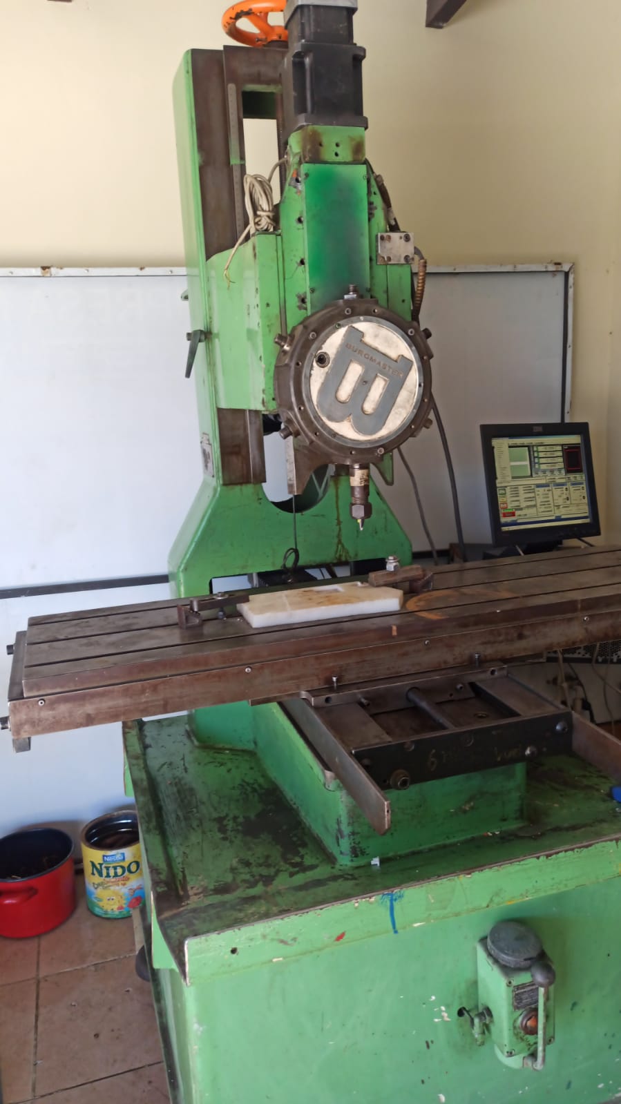
I'm considering buying an old CNC machine, but I haven't been able to find any information about it online, so I'm not sure if it's a good investment.
The machine is based on a Burgmaster with a Föhrenbach DCNC 82V4H plate (built in 1987).
Originally it was equipped with DC servo motors, but after the original controllers failed, the previous owner retrofitted it with NEMA 34 stepper motors, inexpensive digital stepper drivers, and Mach3 running on an old PC through a parallel port.
Mechanically, the machine appears to be in very good condition.
Specifications so far:
Approximate travels: 700 × 500 × 200 mm (X/Y/Z)
Weight: 800 kg
Cast iron construction
Precision dovetail (prismatic) guideways
Fine-pitch lead screws on X and Y
Ball screw on Z
2 kW belt-driven spindle motor with manual pulley speed selection
6-station mechanical indexing turret tool changer
Threaded collet holders on each station (one currently has a 16 mm end mill installed)
I removed the way covers to inspect the machine. The guideways, lead screws, and table all appear to be in excellent condition. There is virtually no visible wear, and the machine seems to have seen relatively little use. Most of the cosmetic damage is simply from having other equipment and materials stacked against it over the years.
My only concern is the spindle. There is a slight amount of radial play that can be felt by hand with a tool installed, although I haven't measured it with a dial indicator yet. I plan to do that on my next visit.
The mechanical turret and spindle arrangement make me think it was originally designed primarily for drilling and tapping, rather than as a conventional milling machine. However, I mainly plan to machine aluminum and plastics (Delrin, nylon, PTFE), not heavy steel.
The alternative would be buying a manual milling machine and performing a complete CNC conversion myself, but by the time I add motors, drives, ball screws, and a controller, the total cost would be very similar to this machine.
If the spindle eventually turns out to be the weak point, I would even consider replacing it with a modern spindle in the future, while keeping the existing cast iron structure.
My questions are:
1. Has anyone seen or worked on a Föhrenbach DCNC machine like this?
2. Does this sound like a drilling/tapping center with limited milling capability, or a light milling machine?
3. Would you consider this a good candidate for a LinuxCNC retrofit?
4. Is the combination of dovetail guideways, lead screws on X/Y, and a ball screw on Z a significant limitation for aluminum machining?
5. Assuming the spindle bearings are still in reasonable condition, would you consider this machine worth buying for around USD 4,500? (kind of a good price in Bolivia)
Any advice or experience would be greatly appreciated.
Thanks!
- lanius3006
- lanius3006
Spindle control by SPI digital potentiometer
Category: HAL
potentiometer is controlled only by SPI communication protocol and as I understand it the default HAL file only sends PWM signal through the designated pin.
How can I configure the HAL file so that the RPi can establish SPI communication with the potentiometer?
- RotarySMP

Schaublin 125-CNC retrofit.
Category: Turning
This is a summary of the various ways I could add sensors, or control to the overall gear ratio.
1/ pull the motor fan, and use the shaft stud to drive an encoder, and then mount an electric cooling fan on the shround for the motor.
++ Seems most robust solution.
++ covers entire drive train with single unit.
++ high resolution, low noise
++ encoder in and encoder out, the gear ratio would be rock steady and real time.
++ does not require pulling the entire drive unit.
++ spare encoder input available on 7i85
2/ Make a little amplifier to scale that 0-10V motor speed output to 0-36V
++ Simplest solution
-- I am not strong in electronics.
-- less resolution than motor encoder
-- lower qualiy signal than encoder
3/ use an optical or hall sensor to count motor fan fins, or CVT features.
++ Slightly simpler that adding an encoder... or not...
-- as it would need the entire drive pulled.
-- less resolution then encoder
-- doesn't sense gearbox ratio.
-- dirty environment, unsuitable for optical sensors.
4/ Add an encoder to the CVT linkage, or to the CVT lead screw.
-- better options above
-- need to pull drive unit.
-- non-linear relationship to ratio
-- needs LUT or algorythm to convert to approx ratio.
-- less resolution than motor encoder
-- doesn't sense gearbox ratio.
5/ Replace the CVT motor with a stepper or servo
-- more work than the better options above
-- large wiring change, add addition servo driver etc
-- need to pull drive unit.
-- non-linear relationship to ratio
-- needs LUT or algorythm to convert to approx ratio.
-- less resolution than motor encoder
-- doesn't sense gearbox ratio.
6/ Use a laser range finder on the CVT belt with a look up table to estimate ratio.
-- dirty environment, optics will likely unreliable over time.
-- better options above
-- non-linear relationship to ratio
-- needs LUT or algorythm to convert to approx ratio.
-- less resolution than motor encoder
-- doesn't sense gearbox ratio.
7/ Using a sensor to detect backgear lever position .
-- dont think there is an external lever, it is internally, pneumatically actuated with no external moving parts.
-- Since it is only shifted stationary, this is the easiest to infer. I can log last position, and cross sheck it using overall ratio, so this seems unnecessary.
8/ adding a gear tooth detector in the gearbox
-- significant effort to pull, disassemble drive unit, and drill hole in housing, design and mount sensor
-- less resolution than motor encoder
-- better options above
Seems to me that the motor encoder would to be the most likely to simply work, and work best. It covers the entire drive train in a single component, offers the highest resolution, and provides (with the spindle encoder) the most direct measurement of overall reduction ratio without noise, interpolation, LUTs etc.
However, before I add a sensor which Schaublin didn't need when they designed this system in the first place, I am thinking of taking one last swing a software solution. My original idea, which I have not yet tried. How accurate does a lathes spindle speed control really need to be?
- divide the CVT range into 5 "fixed ratios", one second apart.
- survey the whole range, generate a look up table of CVT "fixed ratio", and VFD Hz.
- Command the CVT in one second bumps (gear changes).
- largely open loop with VFD frequency interpolated between LUT values.
- Maybe switch to closed loop to fine tune speed (but I am hoping not to need to)
-- if closed loop needed, add PI gains to the LUT.
-- I already have VFD "motor on speed" wired in, and had not thought to use that to gate and freeze the ratio calculation when it would be garbage.
-- when there is steady state operation, use the calculated ratio just to cross check and maybe correct for CVT drift after multiple shifts. In practice, I expect it to be on limits quite often, which is a natural drift reset.
If I can't get that working, and really do need a sensor, I tend to the motor encoder.
- Okojo
- Okojo
rs274ngc as a standalone interpreter — driving grblHAL over UART, no HAL, no RT
Category: General LinuxCNC Questions
### The setup
Hardware: Arduino UNO Q — a single board that combines a Qualcomm QRB2210 (Debian 13 Linux) with an STM32U585 MCU connected via an internal UART (`ttyHS1`). The STM32 runs grblHAL and handles all real-time step generation. The QRB2210 handles G-code interpretation.
### The key insight
`linuxcnc-uspace` ships a Python API for `rs274ngc` that works perfectly outside of a running LinuxCNC instance:
```python
import gcode
from rs274.interpret import Translated, StatMixin
result, seq = gcode.parse(filename, canon, "G21", "")
```
This gives you the full rs274ngc interpreter — canned cycles (G81, G83…), O-word subroutines, G92/G5x coordinate systems, polar coordinates, error checking — with zero HAL setup and no real-time kernel requirement.
The `canon` object intercepts the resulting primitive motion calls (`straight_feed`, `arc_feed`, `spindle_on`…) and translates them to grblHAL commands streamed over serial with `ok`-based flow control.
### What rs274ngc handles automatically
- Canned cycles expanded to primitive G0/G1 moves
- Incremental → absolute coordinate conversion
- G5x / G92 work coordinate offsets
- Polar coordinates
- O-word loops and subroutines
- Unit conversion (G20/G21)
### Architecture
```
G-code file
↓ gcode.parse() — rs274ngc Python API
canon calls (straight_feed, arc_feed …)
↓ Python bridge
G0 / G1 / G2 / G3 over /dev/ttyHS1
↓
grblHAL on STM32U585 — real-time step generation
↓
Stepper drivers / CNC shield
```
Note: rs274ngc canon calls are always in inches (internal unit). All coordinates are multiplied by 25.4 before sending to grblHAL in mm mode.
### Repos
- Bridge (Python, runs on QRB2210): github.com/hoshigarasu/canon-grbl-bridge
- grblHAL firmware (STM32U585 port): github.com/hoshigarasu/grblHAL-STM32U585
Demo video: XY pen plotter drawing a 50mm circle, G-code interpreted by rs274ngc on the QRB2210, executed by grblHAL on the STM32U585. [photos.app.goo.gl/vnDY3CgpnHprdv5dA]
Happy to answer questions about the rs274ngc Python API or the canon interface.
- smc.collins
- smc.collins
Schaublin 125-CNC retrofit.
Category: Turning
Return the speed control pid tuning to linux cnc
Put a closed loop stepper motor on the variator. Here's why
1. step counts are easy targets, so 10 steps = 1 point of gear ratio for example.
2. build a table of Frequency from command to stepper that optimizes torque.
So on Y you have commanded input from Lcnc as frequency
on X you have steps iun the table itself you have gear ratios. Build you selector logic to Always shoot for best torque.
Speed Command from g code
encoder feedback
min max home positions.
then spindle at speed output.
the look up table doesn;t even have to be complex could just be along switch statement, if <200 && >300 spnd cmd gear = 4
that's it. then let linuxcnc handle the fine control. your just grabbing the spnd cmd speed and setting the ratio.
See attached
www.alibaba.com/pla/IHSS57-36-20-Nema23-...rGX0_eUaArgzEALw_wcB
- dbtayl
- dbtayl
Stepper Driver Enable Pin
Category: Basic Configuration
I generally also like to wire things such that "power applied" is "enabled", so that a broken wire or loose connection will only disable the machine.
If you've got other safety hazards from just yanking power (eg, a Z axis that could fall), you may need to consider those.