Search Results (Searched for: stepper spindle)
- motionmasterupgrade
- motionmasterupgrade
01 Apr 2026 02:31
Replied by motionmasterupgrade on topic MotionMaster Upgrade
MotionMaster Upgrade
Category: General LinuxCNC Questions
Thank you!
-existing stuff
I don't see why I cannot use the existing drives for the existing servos. The intention was not to replace those at all. For the VFD, I very much want a water cooled VFD tho I have been told that it takes up a lot of extra vertical real estate. In the end, I'll be a one person outfit for a while anyway, so maybe I can just say screw you OSHA and just deal with the noise on that 16hp spindle. I will never use the full capacity, so as long as I can start it up, I think I should be alright. I imagine I can do some sort of a ramp up start with the VFD settings. That reminds me to check if it works.
-can I mix drives? the swivel head that I have will comes with yaskawa servos and no drives(or I can add drives). I cannot imagine there being as issue to mixing and matching. And concerns with mixing analog/digital?
**********
-if you still want to replace the drives, you have two choices in general: EtherCAT or Mesa with normal step/dir or analog servos (do not bother to look at steppers and close loop steppers)
I'll have to research this. I do not know if the current servos are closed loop ones. The ones on the X and Y axis are mts30r4-42. They have 3 power leads (2 bigger wires, 1 thinner). I've confirmed that I can get a voltage if i turn the servos by hand. The resistance is above the plate, but still under 2ohms. 4 brushes in good condition. There are 4 other pairs of wires that I found out are A, B, Index and Power. Haven't wrapped my head aroud thinking about them from first principles yet. Would this existing hardware affect any of my choices?
-For the Mesa/new drives, i would look for "position and velocity" mode drives (analog +-10V and step/dir) and also with encoder outputs (all have encoder inputs or absolute encoders, usually serial ones) so the loop can be closed in LinuxCNC with both types of control, makes life easier during use. Given the choice between analog and step/dir, choose step/dir.
>>> I'm going to research this paragraph a little more first.
I was wondering if there are good software or schematics for recreating the wiring. I found the Fagor 8055 manual, but it seems more like how to use it rather than how to fix it.
Thank you!
- tommylight

31 Mar 2026 19:51
Replied by tommylight on topic MotionMaster Upgrade
MotionMaster Upgrade
Category: General LinuxCNC Questions
I might not be the best person to reply to this as i absolutely enjoy retrofitting and bringing back to life old machines, so i may be a bit on the "trigger happy" side, but:
-i would try to use the existing drives and motors and VFD/spindle
-seems like those are analog drives, so a Mesa 7i97T would do perfectly fine if you can find one, if not a 7i92T with 7i77 is the same thing, or if those are also scarce a 7i96S with 7i85 and 7i83 should do the same job.
-if you still want to replace the drives, you have two choices in general: EtherCAT or Mesa with normal step/dir or analog servos (do not bother to look at steppers and close loop steppers)
-You will be bombarded by others to choose EtherCAT, i am still avoiding them due to some fuzzy communication issues, but i will test them for sure the fist chance i get.
-For the Mesa/new drives, i would look for "position and velocity" mode drives (analog +-10V and step/dir) and also with encoder outputs (all have encoder inputs or absolute encoders, usually serial ones) so the loop can be closed in LinuxCNC with both types of control, makes life easier during use. Given the choice between analog and step/dir, choose step/dir.
- andypugh

30 Mar 2026 11:48
Replied by andypugh on topic probe basic lath to define a net spindle-index-en spindle.0.index-enable
probe basic lath to define a net spindle-index-en spindle.0.index-enable
Category: HAL
You don't say what the inputs to and2.2 are. That is probably important.
A problem you will have is that spindle.0.index-enable is a bidirectional HAL pin, so can't be directly connected to the output of an and2 block.
You can probably work around this with linuxcnc.org/docs/stable/html/man/man9/tristate_bit.9.html
But, are you sure that your spindle encoder driver doesn't offer e direct, bidirectional, index-enable pin?
There is an example of an index-simulator HAL component here:
forum.linuxcnc.org/24-hal-components/388...ation?start=0#223508
It's written for a stepper spindle, but should work just as well (or just as badly) for an absolute encoder assuming that the encoder has an integer "counts" output.
I was going to suggest watching one bit of the binary counts value and tristate-bit. But that wouldn't zero the counts on index.
There _is_ a way to do it with a sample-hold to capture the counts at index, then subtracting that from the raw counts, that would need a bitslice, mux_generic (set up for signed int), edge, and tristate-bit HAL component.
It's do-able but at that point the custom HAL component makes more sense.
- Hakan
- Hakan
28 Mar 2026 08:09
Replied by Hakan on topic Ethercat Setup help needed for beginner
Ethercat Setup help needed for beginner
Category: EtherCAT
It's easy when you know it.
The problem is to come to know enough.
Anyway, it's not that hard and there is virtually no difference between
setting up stepper drives or servo drives with EtherCAT.
The cia402 layer makes them look the same.
The example I gave is a starting point.
You can copy the files to your installation, change the HALFILE=cia402.hal in the ini file
and give it a try.
But you are going to need to adopt and edit the files to your specific setup.
Number of drives, what number/name they have. And you need to add other
functions like spindle. That's in the sim file. So you need to mix them together
and take the motion part from cia402.hal and the other functions spindle, limits etc
from the sim config.
- Spezidrohne
- Spezidrohne
18 Mar 2026 21:59
Replied by Spezidrohne on topic StepperOnline A6 Servo
StepperOnline A6 Servo
Category: EtherCAT
Update:
i have copied the "working" fies from page 1 into my axis.sim folder, removed the date in their names and put the Basic.hal to be called in the axis.ini file. now the axis.sim does not start and i get this error log:
Print file information:
RUN_IN_PLACE=no
LINUXCNC_DIR=
LINUXCNC_BIN_DIR=/usr/bin
LINUXCNC_TCL_DIR=/usr/lib/tcltk/linuxcnc
LINUXCNC_SCRIPT_DIR=
LINUXCNC_RTLIB_DIR=/usr/lib/linuxcnc/modules
LINUXCNC_CONFIG_DIR=
LINUXCNC_LANG_DIR=/usr/lib/tcltk/linuxcnc/msgs
INIVAR=inivar
HALCMD=halcmd
LINUXCNC_EMCSH=/usr/bin/wish8.6
LINUXCNC - 2.9.8
Machine configuration directory is '/home/christian/linuxcnc/configs/sim.axis'
Machine configuration file is 'axis.ini'
INIFILE=/home/christian/linuxcnc/configs/sim.axis/axis.ini
VERSION=1.1
PARAMETER_FILE=sim.var
TPMOD=
HOMEMOD=
TASK=milltask
HALUI=halui
DISPLAY=axis
COORDINATES=X Y Z
KINEMATICS=trivkins
Starting LinuxCNC...
Starting LinuxCNC server program: linuxcncsvr
Loading Real Time OS, RTAPI, and HAL_LIB modules
Starting LinuxCNC IO program: io
Starting HAL User Interface program: halui
linuxcnc TPMOD=tpmod HOMEMOD=homemod EMCMOT=motmod
Found file(lib): /usr/share/linuxcnc/hallib/core_sim.hal
Found file(lib): /usr/share/linuxcnc/hallib/sim_spindle_encoder.hal
Found file(lib): /usr/share/linuxcnc/hallib/axis_manualtoolchange.hal
Found file(lib): /usr/share/linuxcnc/hallib/simulated_home.hal
Found file(lib): /usr/share/linuxcnc/hallib/check_xyz_constraints.hal
Found file(REL): ./cooling.hal
Found file(REL): ./Basic.hal
Shutting down and cleaning up LinuxCNC...
Removing HAL_LIB, RTAPI, and Real Time OS modules
Removing NML shared memory segments
Debug file information:
Note: Using POSIX realtime
trivkins: already exists
./Basic.hal:3: waitpid failed /usr/bin/rtapi_app trivkins
./Basic.hal:3: /usr/bin/rtapi_app exited without becoming ready
./Basic.hal:3: insmod for trivkins failed, returned -1
2381
Stopping realtime threads
Unloading hal components
Note: Using POSIX realtime
- scsmith1451

10 Mar 2026 20:25
Configuring and Homing dual Y Axes was created by scsmith1451
Configuring and Homing dual Y Axes
Category: PnCConf Wizard
1. Over the winter I modified my DYI Router Mill adding a tandem Y axis and rebuilding my Z axis support with a 2-DF gimbal to true the spindle to the table. Today, I attempted to home the machine however, when the Y axes homed, one triggered before the other causing LCNC to complain about not being able to home one axis while the other is moving off the the home position.
What the the best way to resolve this issue such that both axes travel together, both for homing and moving off the home switch.
2. Using PNCCONF for configuring LCNC with tandem Y axes, when testing the Y axis only one of the steppers responds. Is there something that I missed in PNCCONF that will allow both Y steppers to be tested together?
3. What is the .ini PARAMETER that tells LCNC that two axes are in tandem?
Kind Regards,
- Will_cnc
- Will_cnc
03 Mar 2026 09:33
Replied by Will_cnc on topic Step By Step Help Needed . EL8 Leadshine to PI 5
Step By Step Help Needed . EL8 Leadshine to PI 5
Category: EtherCAT
Hi JRC,Thanks for sharing your spindle configuration — it was really helpful. I’ve also replaced the original spindle motor with a 1000W servo from StepperOnline, and I’m pleased with how it’s performing so far - machine has its limitations but for aluminium it seems good so far. I’ve nearly completed my enclosures; I just need to install a coolant system and add the chip tray and filtration underneath to separate the swarf properly.I’m running the Probe Basic interface as well, which I find very intuitive and easy to use.I have the ATC fitted to my machine but haven’t configured it yet. Do you have an ATC installed on yours? If so, would you be willing to share your configuration files (INI, HAL, etc.)? That would be a huge help.Also, I’d really appreciate a bit more detail on the cylinders you’re using to counterbalance the spindle weight.I’m currently designing a 3D-printed cover for the ATC and would be happy to share it once it’s finished.Thanks again Will
- mooser
- mooser
07 Feb 2026 14:24
Adding Feed Rate (IPM or IPR) to the lathe screen was created by mooser
Adding Feed Rate (IPM or IPR) to the lathe screen
Category: AXIS
Is there an easy way to get the feed rate to show up on the screen somewhere? (old 2.7x version)
For various reasons (I use some css and when it's working well I'd like to know what combination of rpm and feed it's actually using) I'd like to see the actual feed the z-axis is on my lathe as it cuts whatever given diameter. I've got a add-on panel showing the actual spindle RPM so although not as straight forward there should be a way of showing the actual FEED of whatever axis. Since somewhere in there should be the pulse rate of the stepper I think it might be available or would I need to have an encoder on that motor/ballscrew and calculate out the feed that way ???
Mooser
- krille
- krille
02 Feb 2026 18:08
Raspberry pi 5 freze was created by krille
Raspberry pi 5 freze
Category: General LinuxCNC Questions
Hi and so much thanks to the people made all the work with the linuxcnc for raspberry pi 5 ,its a great job.
I have downloaded 4.8.9 and it's a great distro working so fine from beguining and today after a week or two the program stop and freze after 5-10 min. I can still run the stepper from the keyboard and the speedometer on the spindle is i ok and run but the rest of the program stop . the only way to go on is a hard rebot and then it start fine and then the problem starts again . Are there people who can help me in the right direction
I use the byte2bot board in Lathe config. /krister
- zham
- zham
31 Jan 2026 20:28
Need help selecting a Spindle and VFD was created by zham
Need help selecting a Spindle and VFD
Category: Milling Machines
Hi all,
I am completely new to this as you can probably tell. I recently bought an old Gerber Dimension 200 for cheap. It’s a beefy chassis that will allow for a great machine by doing some upgrades. I’m doing a complete overhaul of electronics, spindle, steppers, limit switches etc. All of which will be run off a 7i96 board with the SpinX1. I am a bit confused on how to choose a spindle. I’d like it to integrate with the Mesa board well obviously. The wiring just doesn’t make sense to me on what goes where. If anyone has a solid recommendation for a spindle kit or the like please let me know. Will only be doing wood and aluminum, with the occasional steel sheet. Thank you guys for your time and knowledge.
I am completely new to this as you can probably tell. I recently bought an old Gerber Dimension 200 for cheap. It’s a beefy chassis that will allow for a great machine by doing some upgrades. I’m doing a complete overhaul of electronics, spindle, steppers, limit switches etc. All of which will be run off a 7i96 board with the SpinX1. I am a bit confused on how to choose a spindle. I’d like it to integrate with the Mesa board well obviously. The wiring just doesn’t make sense to me on what goes where. If anyone has a solid recommendation for a spindle kit or the like please let me know. Will only be doing wood and aluminum, with the occasional steel sheet. Thank you guys for your time and knowledge.
- Derriell
- Derriell
28 Jan 2026 01:07 - 28 Jan 2026 02:40
LinuxCNC conversion of Chinese 6040ZH Mach3 router was created by Derriell
LinuxCNC conversion of Chinese 6040ZH Mach3 router
Category: Milling Machines
Hi
I'm new to CNC machines. I want to mill 3D aluminum on a smallish budget. That is the reason why I bough this used machine, my first one. Since I don't want to learn and buy end-of-life software and I like the power and flexibility that comes with open source projects like LinuxCNC the decision to convert it was easy.
It is a Chinese 6040ZH router, 60x40cm bed, 4 axis, rod rails on all axis, 1.5kw spindle, 57BYGH56-4011YD stepper motors (1.26Nm holding torque, 2.8A), 24V system, running mach3 with a USB connection.
Here is a link: www.lygroupchina.com/gantry-cnc-router/h...c-machine-1500w.html


I' ve decided not to invest much into the machine because it has some mechanical design flaws and try to make the best out of it.


Since the controller board runs with a USB-Connection there is no way to run it directly with LinuxCNC. I wanted to know if its possible to reuse the electrical components and it seems so, the stepper motor controllers and the VFD for the spindle. Untested so far.
My plan is to use a MESA i796S board. If you have another suggestion let me know. Unfortunately they are out of stock currently.
The stepper motor controllers are 20 pin modules that stick on some kind of motherboard which also hosts the Mach3 controller, namely a Mach3-R-V1.3. With some reverse engineering I'm confident that I could figure out the function of the pins of the stepper motor controllers. The IC of the drivers seems to be a TB6600HQ or a clone. It has a voltage range of 8-42V, supports operating current of 4.5A, about 150w. It says www.shyidiao.com on them.

Front side from left to right (with the heat spreader remove from the IC. On the bottom left are two optocouplers):
GND, +5V, Pulse, Direction, Stepper RED, Stepper BLUE, Stepper GREEN, Stepper BLACK, +24V, +24V

Back side from left to right (reversed direction from above):
+24V, +24V, Stepper BLACK, Stepper GREEN, Stepper BLUE, Stepper RED, GND, GND, GND, GND
The soldering joints are very likely determining the microstepping of the drivers. If the configuration is from left to right: 1, 1/2, 1/4, 1/8, 1/16 and 1/32 then they are set to a reasonable 1/8.

The spindle driver runs independent of the 24V system. It has two ways to receive an input:
+12V, +5V, i5V (analog Input), SGND (signal ground), FWD (run forward), REV (reverse), BCD2, BCD1, BCD0, ErrB, ErrA

LinuxCNC can handle the TB6600HQ so if its correct they should run with it. Also the spindle can either be run with the analog input or the 3 bit digital one. I still have to decide which one to use. I like the possibility to run the stepper drivers and motors with 36V. That could be a nice upgrade from 24V.
I need a controller board that can handle 4 axis, this VFD, at least one limit switch, touch probe, automatic tool setting and in the future the possibility to attach sensors to close the loop (linear glass scale). The MESA i796S should be able to do that.
A question that is still open to me is how to physically connect the drivers to the MESA board?
Feel free to correct me or give suggestions etc. I hope the MESA cards are back in stock soon.
Bes
I'm new to CNC machines. I want to mill 3D aluminum on a smallish budget. That is the reason why I bough this used machine, my first one. Since I don't want to learn and buy end-of-life software and I like the power and flexibility that comes with open source projects like LinuxCNC the decision to convert it was easy.
It is a Chinese 6040ZH router, 60x40cm bed, 4 axis, rod rails on all axis, 1.5kw spindle, 57BYGH56-4011YD stepper motors (1.26Nm holding torque, 2.8A), 24V system, running mach3 with a USB connection.
Here is a link: www.lygroupchina.com/gantry-cnc-router/h...c-machine-1500w.html
I' ve decided not to invest much into the machine because it has some mechanical design flaws and try to make the best out of it.
- It has rod rails and not linear guides
- The leaver arm on Y-axis to the rod rails is bigger than it needs to be. The rods could have been placed higher
Since the controller board runs with a USB-Connection there is no way to run it directly with LinuxCNC. I wanted to know if its possible to reuse the electrical components and it seems so, the stepper motor controllers and the VFD for the spindle. Untested so far.
My plan is to use a MESA i796S board. If you have another suggestion let me know. Unfortunately they are out of stock currently.
The stepper motor controllers are 20 pin modules that stick on some kind of motherboard which also hosts the Mach3 controller, namely a Mach3-R-V1.3. With some reverse engineering I'm confident that I could figure out the function of the pins of the stepper motor controllers. The IC of the drivers seems to be a TB6600HQ or a clone. It has a voltage range of 8-42V, supports operating current of 4.5A, about 150w. It says www.shyidiao.com on them.
Front side from left to right (with the heat spreader remove from the IC. On the bottom left are two optocouplers):
GND, +5V, Pulse, Direction, Stepper RED, Stepper BLUE, Stepper GREEN, Stepper BLACK, +24V, +24V
Back side from left to right (reversed direction from above):
+24V, +24V, Stepper BLACK, Stepper GREEN, Stepper BLUE, Stepper RED, GND, GND, GND, GND
The soldering joints are very likely determining the microstepping of the drivers. If the configuration is from left to right: 1, 1/2, 1/4, 1/8, 1/16 and 1/32 then they are set to a reasonable 1/8.
The spindle driver runs independent of the 24V system. It has two ways to receive an input:
- an analog input with voltage range 0-5V, currently wired to a potentiometer to manually control the spindle
- three digital inputs, allowing for 8 fixed speeds
+12V, +5V, i5V (analog Input), SGND (signal ground), FWD (run forward), REV (reverse), BCD2, BCD1, BCD0, ErrB, ErrA
LinuxCNC can handle the TB6600HQ so if its correct they should run with it. Also the spindle can either be run with the analog input or the 3 bit digital one. I still have to decide which one to use. I like the possibility to run the stepper drivers and motors with 36V. That could be a nice upgrade from 24V.
I need a controller board that can handle 4 axis, this VFD, at least one limit switch, touch probe, automatic tool setting and in the future the possibility to attach sensors to close the loop (linear glass scale). The MESA i796S should be able to do that.
A question that is still open to me is how to physically connect the drivers to the MESA board?
- Buy these 20 Pin sockets and make a board with them? Probably costly and time consuming
- Solder the connections directly to the pins on the module and attach them somehow. Dirty, easy, quick, downside is, I can't plug them back in the motherboard
- Solder the connecting wires to the motherboard and plug the drivers into the board. Could be neat because the machine could be back ported to Mach3. Possible unwanted side effects on the board. Of course I would unplug the Mach3 controller chip.
Feel free to correct me or give suggestions etc. I hope the MESA cards are back in stock soon.
Bes
- Mark Kraus
- Mark Kraus
26 Jan 2026 21:40
Having Trouble getting encoder to work. Amt102-v 5 wire was created by Mark Kraus
Having Trouble getting encoder to work. Amt102-v 5 wire
Category: Basic Configuration
I was wondering if someone could take a look at my hal and ini files and tell me why i have not encoder count on my halshow but the at speed light is green. All of this worked in uccnc before i switched over. I set the encoder to 1024 ppr. I have 5volts going to encoder.
# Generated by PNCconf at Mon Jan 26 15:37:21 2026
# Using LinuxCNC version: Master (2.9)
# If you make changes to this file, they will be
# overwritten when you run PNCconf again
loadrt [KINS]KINEMATICS
loadrt [EMCMOT]EMCMOT servo_period_nsec=[EMCMOT]SERVO_PERIOD num_joints=[KINS]JOINTS
loadrt hostmot2
loadrt hm2_eth board_ip="10.10.10.10" config="num_encoders=1 num_pwmgens=1 num_stepgens=5 sserial_port_0=0xxxxxxx"
setp hm2_7i96s.0.pwmgen.pwm_frequency 5000
setp hm2_7i96s.0.pwmgen.pdm_frequency 6000000
setp hm2_7i96s.0.watchdog.timeout_ns 5000000
loadrt pid names=pid.x,pid.y,pid.z,pid.s
loadrt near
addf hm2_7i96s.0.read servo-thread
addf motion-command-handler servo-thread
addf motion-controller servo-thread
addf pid.x.do-pid-calcs servo-thread
addf pid.y.do-pid-calcs servo-thread
addf pid.z.do-pid-calcs servo-thread
addf pid.s.do-pid-calcs servo-thread
addf near.0 servo-thread
addf hm2_7i96s.0.write servo-thread
setp hm2_7i96s.0.dpll.01.timer-us -50
setp hm2_7i96s.0.stepgen.timer-number 1
# external output signals
# --- SPINDLE-BRAKE ---
net spindle-brake => hm2_7i96s.0.ssr.00.out-00
# --- COOLANT-MIST ---
net coolant-mist => hm2_7i96s.0.ssr.00.out-01
# --- SPINDLE-CW ---
net spindle-cw => hm2_7i96s.0.outm.00.out-04
# --- SPINDLE-CCW ---
net spindle-ccw => hm2_7i96s.0.outm.00.out-05
# external input signals
# --- ESTOP-EXT ---
net estop-ext <= hm2_7i96s.0.inm.00.input-00
# --- ALL-LIMIT ---
net all-limit <= hm2_7i96s.0.inm.00.input-01
#*******************
# AXIS X JOINT 0
#*******************
setp pid.x.Pgain [JOINT_0]P
setp pid.x.Igain [JOINT_0]I
setp pid.x.Dgain [JOINT_0]D
setp pid.x.bias [JOINT_0]BIAS
setp pid.x.FF0 [JOINT_0]FF0
setp pid.x.FF1 [JOINT_0]FF1
setp pid.x.FF2 [JOINT_0]FF2
setp pid.x.deadband [JOINT_0]DEADBAND
setp pid.x.maxoutput [JOINT_0]MAX_OUTPUT
setp pid.x.error-previous-target true
# This setting is to limit bogus stepgen
# velocity corrections caused by position
# feedback sample time jitter.
setp pid.x.maxerror 0.000500
net x-index-enable => pid.x.index-enable
net x-enable => pid.x.enable
net x-pos-cmd => pid.x.command
net x-pos-fb => pid.x.feedback
net x-output <= pid.x.output
# Step Gen signals/setup
setp hm2_7i96s.0.stepgen.00.dirsetup [JOINT_0]DIRSETUP
setp hm2_7i96s.0.stepgen.00.dirhold [JOINT_0]DIRHOLD
setp hm2_7i96s.0.stepgen.00.steplen [JOINT_0]STEPLEN
setp hm2_7i96s.0.stepgen.00.stepspace [JOINT_0]STEPSPACE
setp hm2_7i96s.0.stepgen.00.position-scale [JOINT_0]STEP_SCALE
setp hm2_7i96s.0.stepgen.00.step_type 0
setp hm2_7i96s.0.stepgen.00.control-type 1
setp hm2_7i96s.0.stepgen.00.maxaccel [JOINT_0]STEPGEN_MAXACCEL
setp hm2_7i96s.0.stepgen.00.maxvel [JOINT_0]STEPGEN_MAXVEL
# ---closedloop stepper signals---
net x-pos-cmd <= joint.0.motor-pos-cmd
net x-vel-cmd <= joint.0.vel-cmd
net x-output => hm2_7i96s.0.stepgen.00.velocity-cmd
net x-pos-fb <= hm2_7i96s.0.stepgen.00.position-fb
net x-pos-fb => joint.0.motor-pos-fb
net x-enable <= joint.0.amp-enable-out
net x-enable => hm2_7i96s.0.stepgen.00.enable
# ---setup home / limit switch signals---
net x-home-sw => joint.0.home-sw-in
net all-limit => joint.0.neg-lim-sw-in
net all-limit => joint.0.pos-lim-sw-in
#*******************
# AXIS Y JOINT 1
#*******************
setp pid.y.Pgain [JOINT_1]P
setp pid.y.Igain [JOINT_1]I
setp pid.y.Dgain [JOINT_1]D
setp pid.y.bias [JOINT_1]BIAS
setp pid.y.FF0 [JOINT_1]FF0
setp pid.y.FF1 [JOINT_1]FF1
setp pid.y.FF2 [JOINT_1]FF2
setp pid.y.deadband [JOINT_1]DEADBAND
setp pid.y.maxoutput [JOINT_1]MAX_OUTPUT
setp pid.y.error-previous-target true
# This setting is to limit bogus stepgen
# velocity corrections caused by position
# feedback sample time jitter.
setp pid.y.maxerror 0.000500
net y-index-enable => pid.y.index-enable
net y-enable => pid.y.enable
net y-pos-cmd => pid.y.command
net y-pos-fb => pid.y.feedback
net y-output <= pid.y.output
# Step Gen signals/setup
setp hm2_7i96s.0.stepgen.01.dirsetup [JOINT_1]DIRSETUP
setp hm2_7i96s.0.stepgen.01.dirhold [JOINT_1]DIRHOLD
setp hm2_7i96s.0.stepgen.01.steplen [JOINT_1]STEPLEN
setp hm2_7i96s.0.stepgen.01.stepspace [JOINT_1]STEPSPACE
setp hm2_7i96s.0.stepgen.01.position-scale [JOINT_1]STEP_SCALE
setp hm2_7i96s.0.stepgen.01.step_type 0
setp hm2_7i96s.0.stepgen.01.control-type 1
setp hm2_7i96s.0.stepgen.01.maxaccel [JOINT_1]STEPGEN_MAXACCEL
setp hm2_7i96s.0.stepgen.01.maxvel [JOINT_1]STEPGEN_MAXVEL
# ---closedloop stepper signals---
net y-pos-cmd <= joint.1.motor-pos-cmd
net y-vel-cmd <= joint.1.vel-cmd
net y-output => hm2_7i96s.0.stepgen.01.velocity-cmd
net y-pos-fb <= hm2_7i96s.0.stepgen.01.position-fb
net y-pos-fb => joint.1.motor-pos-fb
net y-enable <= joint.1.amp-enable-out
net y-enable => hm2_7i96s.0.stepgen.01.enable
# ---setup home / limit switch signals---
net y-home-sw => joint.1.home-sw-in
net all-limit => joint.1.neg-lim-sw-in
net all-limit => joint.1.pos-lim-sw-in
#*******************
# AXIS Z JOINT 2
#*******************
setp pid.z.Pgain [JOINT_2]P
setp pid.z.Igain [JOINT_2]I
setp pid.z.Dgain [JOINT_2]D
setp pid.z.bias [JOINT_2]BIAS
setp pid.z.FF0 [JOINT_2]FF0
setp pid.z.FF1 [JOINT_2]FF1
setp pid.z.FF2 [JOINT_2]FF2
setp pid.z.deadband [JOINT_2]DEADBAND
setp pid.z.maxoutput [JOINT_2]MAX_OUTPUT
setp pid.z.error-previous-target true
# This setting is to limit bogus stepgen
# velocity corrections caused by position
# feedback sample time jitter.
setp pid.z.maxerror 0.000500
net z-index-enable => pid.z.index-enable
net z-enable => pid.z.enable
net z-pos-cmd => pid.z.command
net z-pos-fb => pid.z.feedback
net z-output <= pid.z.output
# Step Gen signals/setup
setp hm2_7i96s.0.stepgen.02.dirsetup [JOINT_2]DIRSETUP
setp hm2_7i96s.0.stepgen.02.dirhold [JOINT_2]DIRHOLD
setp hm2_7i96s.0.stepgen.02.steplen [JOINT_2]STEPLEN
setp hm2_7i96s.0.stepgen.02.stepspace [JOINT_2]STEPSPACE
setp hm2_7i96s.0.stepgen.02.position-scale [JOINT_2]STEP_SCALE
setp hm2_7i96s.0.stepgen.02.step_type 0
setp hm2_7i96s.0.stepgen.02.control-type 1
setp hm2_7i96s.0.stepgen.02.maxaccel [JOINT_2]STEPGEN_MAXACCEL
setp hm2_7i96s.0.stepgen.02.maxvel [JOINT_2]STEPGEN_MAXVEL
# ---closedloop stepper signals---
net z-pos-cmd <= joint.2.motor-pos-cmd
net z-vel-cmd <= joint.2.vel-cmd
net z-output => hm2_7i96s.0.stepgen.02.velocity-cmd
net z-pos-fb <= hm2_7i96s.0.stepgen.02.position-fb
net z-pos-fb => joint.2.motor-pos-fb
net z-enable <= joint.2.amp-enable-out
net z-enable => hm2_7i96s.0.stepgen.02.enable
# ---setup home / limit switch signals---
net z-home-sw => joint.2.home-sw-in
net all-limit => joint.2.neg-lim-sw-in
net all-limit => joint.2.pos-lim-sw-in
#*******************
# SPINDLE
#*******************
setp pid.s.Pgain [SPINDLE_0]P
setp pid.s.Igain [SPINDLE_0]I
setp pid.s.Dgain [SPINDLE_0]D
setp pid.s.bias [SPINDLE_0]BIAS
setp pid.s.FF0 [SPINDLE_0]FF0
setp pid.s.FF1 [SPINDLE_0]FF1
setp pid.s.FF2 [SPINDLE_0]FF2
setp pid.s.deadband [SPINDLE_0]DEADBAND
setp pid.s.maxoutput [SPINDLE_0]MAX_OUTPUT
setp pid.s.error-previous-target true
net spindle-index-enable => pid.s.index-enable
net spindle-enable => pid.s.enable
net spindle-vel-cmd-rpm => pid.s.command
net spindle-vel-fb-rpm => pid.s.feedback
net spindle-output <= pid.s.output
# ---PWM Generator signals/setup---
setp hm2_7i96s.0.pwmgen.00.output-type 1
setp hm2_7i96s.0.pwmgen.00.scale [SPINDLE_0]OUTPUT_SCALE
net spindle-output => hm2_7i96s.0.pwmgen.00.value
net spindle-enable => hm2_7i96s.0.pwmgen.00.enable
# ---Encoder feedback signals/setup---
setp hm2_7i96s.0.encoder.00.counter-mode 0
setp hm2_7i96s.0.encoder.00.filter 1
setp hm2_7i96s.0.encoder.00.index-invert 0
setp hm2_7i96s.0.encoder.00.index-mask 0
setp hm2_7i96s.0.encoder.00.index-mask-invert 0
setp hm2_7i96s.0.encoder.00.scale [SPINDLE_0]ENCODER_SCALE
net spindle-revs <= hm2_7i96s.0.encoder.00.position
net spindle-vel-fb-rps <= hm2_7i96s.0.encoder.00.velocity
net spindle-vel-fb-rpm <= hm2_7i96s.0.encoder.00.velocity-rpm
net spindle-index-enable <=> hm2_7i96s.0.encoder.00.index-enable
# ---setup spindle control signals---
net spindle-vel-cmd-rps <= spindle.0.speed-out-rps
net spindle-vel-cmd-rps-abs <= spindle.0.speed-out-rps-abs
net spindle-vel-cmd-rpm <= spindle.0.speed-out
net spindle-vel-cmd-rpm-abs <= spindle.0.speed-out-abs
net spindle-enable <= spindle.0.on
net spindle-cw <= spindle.0.forward
net spindle-ccw <= spindle.0.reverse
net spindle-brake <= spindle.0.brake
net spindle-revs => spindle.0.revs
net spindle-at-speed => spindle.0.at-speed
net spindle-vel-fb-rps => spindle.0.speed-in
net spindle-index-enable <=> spindle.0.index-enable
# ---Setup spindle at speed signals---
net spindle-vel-cmd-rps => near.0.in1
net spindle-vel-fb-rps => near.0.in2
net spindle-at-speed <= near.0.out
setp near.0.scale 1.000000
setp near.0.difference 1.666667
#******************************
# connect miscellaneous signals
#******************************
# ---HALUI signals---
net axis-select-x halui.axis.x.select
net jog-x-pos halui.axis.x.plus
net jog-x-neg halui.axis.x.minus
net jog-x-analog halui.axis.x.analog
net x-is-homed halui.joint.0.is-homed
net axis-select-y halui.axis.y.select
net jog-y-pos halui.axis.y.plus
net jog-y-neg halui.axis.y.minus
net jog-y-analog halui.axis.y.analog
net y-is-homed halui.joint.1.is-homed
net axis-select-z halui.axis.z.select
net jog-z-pos halui.axis.z.plus
net jog-z-neg halui.axis.z.minus
net jog-z-analog halui.axis.z.analog
net z-is-homed halui.joint.2.is-homed
net jog-selected-pos halui.axis.selected.plus
net jog-selected-neg halui.axis.selected.minus
net spindle-manual-cw halui.spindle.0.forward
net spindle-manual-ccw halui.spindle.0.reverse
net spindle-manual-stop halui.spindle.0.stop
net machine-is-on halui.machine.is-on
net jog-speed halui.axis.jog-speed
net MDI-mode halui.mode.is-mdi
# ---coolant signals---
net coolant-mist <= iocontrol.0.coolant-mist
net coolant-flood <= iocontrol.0.coolant-flood
# ---probe signal---
net probe-in => motion.probe-input
# ---motion control signals---
net in-position <= motion.in-position
net machine-is-enabled <= motion.motion-enabled
# ---digital in / out signals---
# ---estop signals---
net estop-out <= iocontrol.0.user-enable-out
net estop-ext => iocontrol.0.emc-enable-in
# ---manual tool change signals---
net tool-change-request <= iocontrol.0.tool-change
net tool-change-confirmed => iocontrol.0.tool-changed
net tool-number <= iocontrol.0.tool-prep-number
# ---ignore tool prepare requests---
net tool-prepare-loopback iocontrol.0.tool-prepare => iocontrol.0.tool-prepared
# Generated by PNCconf at Mon Jan 26 15:37:21 2026
# Using LinuxCNC version: Master (2.9)
# If you make changes to this file, they will be
# overwritten when you run PNCconf again
[EMC]
MACHINE = Bridgeportsimple2
DEBUG = 0
VERSION = 1.1
[DISPLAY]
DISPLAY = qtvcp qtdragon
PREFERENCE_FILE_PATH = WORKINGFOLDER/qtdragon.pref
POSITION_OFFSET = RELATIVE
POSITION_FEEDBACK = ACTUAL
MAX_FEED_OVERRIDE = 2.000000
MAX_SPINDLE_0_OVERRIDE = 2.000000
MIN_SPINDLE_0_OVERRIDE = 0.500000
DEFAULT_SPINDLE_0_SPEED = 500
MIN_SPINDLE_0_SPEED = 100
MAX_SPINDLE_0_SPEED = 2500
INTRO_GRAPHIC = linuxcnc.gif
INTRO_TIME = 5
PROGRAM_PREFIX = /home/debian/linuxcnc/nc_files
INCREMENTS = .1in .05in .01in .005in .001in .0005in .0001in
POSITION_FEEDBACK = ACTUAL
DEFAULT_LINEAR_VELOCITY = 0.250000
MAX_LINEAR_VELOCITY = 1.000000
MIN_LINEAR_VELOCITY = 0.016670
DEFAULT_ANGULAR_VELOCITY = 12.000000
MAX_ANGULAR_VELOCITY = 180.000000
MIN_ANGULAR_VELOCITY = 1.666667
EDITOR = gedit
GEOMETRY = xyz
CYCLE_TIME = 100
[MDI_COMMAND_LIST]
MDI_COMMAND = G0 Z0;X0 Y0
MDI_COMMAND = G53 G0 Z0;G53 G0 X0 Y0
[FILTER]
PROGRAM_EXTENSION = .png,.gif,.jpg Greyscale Depth Image
PROGRAM_EXTENSION = .py Python Script
png = image-to-gcode
gif = image-to-gcode
jpg = image-to-gcode
py = python
[TASK]
TASK = milltask
CYCLE_TIME = 0.010
[RS274NGC]
PARAMETER_FILE = linuxcnc.var
RS274NGC_STARTUP_CODE = G20 G40 G90 G94 G97 G64 P0.001
[EMCMOT]
EMCMOT = motmod
COMM_TIMEOUT = 1.0
SERVO_PERIOD = 1200000
[HMOT]
# **** This is for info only ****
CARD0=hm2_7i96s.0
[HAL]
HALUI = halui
HALFILE = Bridgeportsimple2.hal
HALFILE = custom.hal
POSTGUI_HALFILE = qtvcp_postgui.hal
POSTGUI_HALFILE = custom_postgui.hal
SHUTDOWN = shutdown.hal
[HALUI]
[KINS]
JOINTS = 3
KINEMATICS = trivkins coordinates=XYZ
[TRAJ]
COORDINATES = XYZ
LINEAR_UNITS = inch
ANGULAR_UNITS = degree
DEFAULT_LINEAR_VELOCITY = 0.15
MAX_LINEAR_VELOCITY = 1.48
[EMCIO]
EMCIO = io
CYCLE_TIME = 0.100
TOOL_TABLE = tool.tbl
#******************************************
[AXIS_X]
MAX_VELOCITY = 1.1666666666666667
MAX_ACCELERATION = 10.0
MIN_LIMIT = -7.0
MAX_LIMIT = 8.0
[JOINT_0]
TYPE = LINEAR
HOME = 0.0
FERROR = 0.5
MIN_FERROR = 0.05
MAX_VELOCITY = 1.1666666666666667
MAX_ACCELERATION = 10.0
# The values below should be 25% larger than MAX_VELOCITY and MAX_ACCELERATION
# If using BACKLASH compensation STEPGEN_MAXACCEL should be 100% larger.
STEPGEN_MAXVEL = 2.33
STEPGEN_MAXACCEL = 20.00
P = 1000.0
I = 0.0
D = 0.0
FF0 = 0.0
FF1 = 1.0
FF2 = 0.0
BIAS = 0.0
DEADBAND = 0.0
MAX_OUTPUT = 0.0
# these are in nanoseconds
DIRSETUP = 5000
DIRHOLD = 5000
STEPLEN = 5000
STEPSPACE = 5000
STEP_SCALE = 4000.0
BACKLASH = 0.001
MIN_LIMIT = -7.0
MAX_LIMIT = 8.0
HOME_OFFSET = 0.0
HOME_SEQUENCE = 1
#******************************************
#******************************************
[AXIS_Y]
MAX_VELOCITY = 1.0
MAX_ACCELERATION = 10.0
MIN_LIMIT = -8.0
MAX_LIMIT = 8.0
[JOINT_1]
TYPE = LINEAR
HOME = 0.0
FERROR = 0.5
MIN_FERROR = 0.05
MAX_VELOCITY = 1.0
MAX_ACCELERATION = 10.0
# The values below should be 25% larger than MAX_VELOCITY and MAX_ACCELERATION
# If using BACKLASH compensation STEPGEN_MAXACCEL should be 100% larger.
STEPGEN_MAXVEL = 2.00
STEPGEN_MAXACCEL = 20.00
P = 1000.0
I = 0.0
D = 0.0
FF0 = 0.0
FF1 = 1.0
FF2 = 0.0
BIAS = 0.0
DEADBAND = 0.0
MAX_OUTPUT = 0.0
# these are in nanoseconds
DIRSETUP = 5000
DIRHOLD = 5000
STEPLEN = 5000
STEPSPACE = 5000
STEP_SCALE = -16000.0
BACKLASH = 0.001
MIN_LIMIT = -8.0
MAX_LIMIT = 8.0
HOME_OFFSET = 0.0
HOME_SEQUENCE = 2
#******************************************
#******************************************
[AXIS_Z]
MAX_VELOCITY = 1.4833333333333334
MAX_ACCELERATION = 10.0
MIN_LIMIT = -3.0
MAX_LIMIT = 5.0
[JOINT_2]
TYPE = LINEAR
HOME = 0.0
FERROR = 0.5
MIN_FERROR = 0.05
MAX_VELOCITY = 1.4833333333333334
MAX_ACCELERATION = 10.0
# The values below should be 25% larger than MAX_VELOCITY and MAX_ACCELERATION
# If using BACKLASH compensation STEPGEN_MAXACCEL should be 100% larger.
STEPGEN_MAXVEL = 2.97
STEPGEN_MAXACCEL = 20.00
P = 1000.0
I = 0.0
D = 0.0
FF0 = 0.0
FF1 = 1.0
FF2 = 0.0
BIAS = 0.0
DEADBAND = 0.0
MAX_OUTPUT = 0.0
# these are in nanoseconds
DIRSETUP = 2000
DIRHOLD = 2000
STEPLEN = 2000
STEPSPACE = 2000
STEP_SCALE = -65000.0
BACKLASH = 0.001
MIN_LIMIT = -3.0
MAX_LIMIT = 5.0
HOME_OFFSET = 0.0
HOME_SEQUENCE = 1
#******************************************
[SPINDLE_0]
P = 0.0
I = 0.0
D = 0.0
FF0 = 1.0
FF1 = 0.0
FF2 = 0.0
BIAS = 0.0
DEADBAND = 0.0
MAX_OUTPUT = 2000.0
ENCODER_SCALE = 4096.0
OUTPUT_SCALE = 2000
OUTPUT_MIN_LIMIT = -2000
OUTPUT_MAX_LIMIT = 2000
# Include your custom HAL commands here
# This file will not be overwritten when you run PNCconf again
# Custom spindle analog PWM setup for 7i96S TB2 (pot replacement mode)
# This file will not be overwritten when you run PNCconf again
setp hm2_7i96s.0.pwmgen.00.scale 3500 # Max RPM = full ~10V output
# Let pncconf's existing connection handle the value signal
# (it usually connects pwmgen.00.value to spindle-output or similar)
# Enable the PWMgen when spindle is on
#net spindle-on spindle.0.on => hm2_7i96s.0.pwmgen.00.enable
# Optional: Digital FWD enable on TB3 (OUT4 for example)
# net spindle-on hm2_7i96s.0.ssr.00.out-04 # Adjust out-04 to match your assignment
# ============================================
# Spindle Encoder RPM Display Fix (Ultimate Final - No Encoder Pin Nets)
# Only setp for encoder config + single bridge net on display side
# Zero duplicate warnings, pncconf-safe
# ============================================
# Encoder configuration (setp only - completely safe)
setp hm2_7i96s.0.encoder.00.counter-mode 0 # Quadrature A/B/Z
setp hm2_7i96s.0.encoder.00.filter 1 # Filter noise/blips
# Scale - CHANGE THIS to your actual PPR × 4
# Test: Spin shaft 1 full turn by hand → count change / 4 = PPR
# Common AMT102-V settings: 400 CPR → 1600, 1000 → 4000, 1024 → 4096
setp hm2_7i96s.0.encoder.00.scale 4096 # ← EDIT THIS LINE !!!
# Optional: Invert A/B if direction is reversed (counts decrease on forward spin)
# setp hm2_7i96s.0.encoder.00.phase-a-invert 1
# setp hm2_7i96s.0.encoder.00.phase-b-invert 1
# Route pncconf's existing velocity signal to QtDragon RPM display pin
# This is the only net - it never touches encoder pins
# net spindle-vel-fb-rpm => spindle.0.speed-in-rpm
# Optional: Extra smoothing to eliminate random blips when stopped
# Uncomment if blips persist after scale fix
# loadrt lowpass
# addf lowpass.0 servo-thread
# setp lowpass.0.gain 0.05 # Lower = smoother (0.01–0.1 range)
# net spindle-velocity-filtered lowpass.0.out => spindle.0.speed-in-rpm
# Generated by PNCconf at Mon Jan 26 15:37:21 2026
# Using LinuxCNC version: Master (2.9)
# If you make changes to this file, they will be
# overwritten when you run PNCconf again
loadrt [KINS]KINEMATICS
loadrt [EMCMOT]EMCMOT servo_period_nsec=[EMCMOT]SERVO_PERIOD num_joints=[KINS]JOINTS
loadrt hostmot2
loadrt hm2_eth board_ip="10.10.10.10" config="num_encoders=1 num_pwmgens=1 num_stepgens=5 sserial_port_0=0xxxxxxx"
setp hm2_7i96s.0.pwmgen.pwm_frequency 5000
setp hm2_7i96s.0.pwmgen.pdm_frequency 6000000
setp hm2_7i96s.0.watchdog.timeout_ns 5000000
loadrt pid names=pid.x,pid.y,pid.z,pid.s
loadrt near
addf hm2_7i96s.0.read servo-thread
addf motion-command-handler servo-thread
addf motion-controller servo-thread
addf pid.x.do-pid-calcs servo-thread
addf pid.y.do-pid-calcs servo-thread
addf pid.z.do-pid-calcs servo-thread
addf pid.s.do-pid-calcs servo-thread
addf near.0 servo-thread
addf hm2_7i96s.0.write servo-thread
setp hm2_7i96s.0.dpll.01.timer-us -50
setp hm2_7i96s.0.stepgen.timer-number 1
# external output signals
# --- SPINDLE-BRAKE ---
net spindle-brake => hm2_7i96s.0.ssr.00.out-00
# --- COOLANT-MIST ---
net coolant-mist => hm2_7i96s.0.ssr.00.out-01
# --- SPINDLE-CW ---
net spindle-cw => hm2_7i96s.0.outm.00.out-04
# --- SPINDLE-CCW ---
net spindle-ccw => hm2_7i96s.0.outm.00.out-05
# external input signals
# --- ESTOP-EXT ---
net estop-ext <= hm2_7i96s.0.inm.00.input-00
# --- ALL-LIMIT ---
net all-limit <= hm2_7i96s.0.inm.00.input-01
#*******************
# AXIS X JOINT 0
#*******************
setp pid.x.Pgain [JOINT_0]P
setp pid.x.Igain [JOINT_0]I
setp pid.x.Dgain [JOINT_0]D
setp pid.x.bias [JOINT_0]BIAS
setp pid.x.FF0 [JOINT_0]FF0
setp pid.x.FF1 [JOINT_0]FF1
setp pid.x.FF2 [JOINT_0]FF2
setp pid.x.deadband [JOINT_0]DEADBAND
setp pid.x.maxoutput [JOINT_0]MAX_OUTPUT
setp pid.x.error-previous-target true
# This setting is to limit bogus stepgen
# velocity corrections caused by position
# feedback sample time jitter.
setp pid.x.maxerror 0.000500
net x-index-enable => pid.x.index-enable
net x-enable => pid.x.enable
net x-pos-cmd => pid.x.command
net x-pos-fb => pid.x.feedback
net x-output <= pid.x.output
# Step Gen signals/setup
setp hm2_7i96s.0.stepgen.00.dirsetup [JOINT_0]DIRSETUP
setp hm2_7i96s.0.stepgen.00.dirhold [JOINT_0]DIRHOLD
setp hm2_7i96s.0.stepgen.00.steplen [JOINT_0]STEPLEN
setp hm2_7i96s.0.stepgen.00.stepspace [JOINT_0]STEPSPACE
setp hm2_7i96s.0.stepgen.00.position-scale [JOINT_0]STEP_SCALE
setp hm2_7i96s.0.stepgen.00.step_type 0
setp hm2_7i96s.0.stepgen.00.control-type 1
setp hm2_7i96s.0.stepgen.00.maxaccel [JOINT_0]STEPGEN_MAXACCEL
setp hm2_7i96s.0.stepgen.00.maxvel [JOINT_0]STEPGEN_MAXVEL
# ---closedloop stepper signals---
net x-pos-cmd <= joint.0.motor-pos-cmd
net x-vel-cmd <= joint.0.vel-cmd
net x-output => hm2_7i96s.0.stepgen.00.velocity-cmd
net x-pos-fb <= hm2_7i96s.0.stepgen.00.position-fb
net x-pos-fb => joint.0.motor-pos-fb
net x-enable <= joint.0.amp-enable-out
net x-enable => hm2_7i96s.0.stepgen.00.enable
# ---setup home / limit switch signals---
net x-home-sw => joint.0.home-sw-in
net all-limit => joint.0.neg-lim-sw-in
net all-limit => joint.0.pos-lim-sw-in
#*******************
# AXIS Y JOINT 1
#*******************
setp pid.y.Pgain [JOINT_1]P
setp pid.y.Igain [JOINT_1]I
setp pid.y.Dgain [JOINT_1]D
setp pid.y.bias [JOINT_1]BIAS
setp pid.y.FF0 [JOINT_1]FF0
setp pid.y.FF1 [JOINT_1]FF1
setp pid.y.FF2 [JOINT_1]FF2
setp pid.y.deadband [JOINT_1]DEADBAND
setp pid.y.maxoutput [JOINT_1]MAX_OUTPUT
setp pid.y.error-previous-target true
# This setting is to limit bogus stepgen
# velocity corrections caused by position
# feedback sample time jitter.
setp pid.y.maxerror 0.000500
net y-index-enable => pid.y.index-enable
net y-enable => pid.y.enable
net y-pos-cmd => pid.y.command
net y-pos-fb => pid.y.feedback
net y-output <= pid.y.output
# Step Gen signals/setup
setp hm2_7i96s.0.stepgen.01.dirsetup [JOINT_1]DIRSETUP
setp hm2_7i96s.0.stepgen.01.dirhold [JOINT_1]DIRHOLD
setp hm2_7i96s.0.stepgen.01.steplen [JOINT_1]STEPLEN
setp hm2_7i96s.0.stepgen.01.stepspace [JOINT_1]STEPSPACE
setp hm2_7i96s.0.stepgen.01.position-scale [JOINT_1]STEP_SCALE
setp hm2_7i96s.0.stepgen.01.step_type 0
setp hm2_7i96s.0.stepgen.01.control-type 1
setp hm2_7i96s.0.stepgen.01.maxaccel [JOINT_1]STEPGEN_MAXACCEL
setp hm2_7i96s.0.stepgen.01.maxvel [JOINT_1]STEPGEN_MAXVEL
# ---closedloop stepper signals---
net y-pos-cmd <= joint.1.motor-pos-cmd
net y-vel-cmd <= joint.1.vel-cmd
net y-output => hm2_7i96s.0.stepgen.01.velocity-cmd
net y-pos-fb <= hm2_7i96s.0.stepgen.01.position-fb
net y-pos-fb => joint.1.motor-pos-fb
net y-enable <= joint.1.amp-enable-out
net y-enable => hm2_7i96s.0.stepgen.01.enable
# ---setup home / limit switch signals---
net y-home-sw => joint.1.home-sw-in
net all-limit => joint.1.neg-lim-sw-in
net all-limit => joint.1.pos-lim-sw-in
#*******************
# AXIS Z JOINT 2
#*******************
setp pid.z.Pgain [JOINT_2]P
setp pid.z.Igain [JOINT_2]I
setp pid.z.Dgain [JOINT_2]D
setp pid.z.bias [JOINT_2]BIAS
setp pid.z.FF0 [JOINT_2]FF0
setp pid.z.FF1 [JOINT_2]FF1
setp pid.z.FF2 [JOINT_2]FF2
setp pid.z.deadband [JOINT_2]DEADBAND
setp pid.z.maxoutput [JOINT_2]MAX_OUTPUT
setp pid.z.error-previous-target true
# This setting is to limit bogus stepgen
# velocity corrections caused by position
# feedback sample time jitter.
setp pid.z.maxerror 0.000500
net z-index-enable => pid.z.index-enable
net z-enable => pid.z.enable
net z-pos-cmd => pid.z.command
net z-pos-fb => pid.z.feedback
net z-output <= pid.z.output
# Step Gen signals/setup
setp hm2_7i96s.0.stepgen.02.dirsetup [JOINT_2]DIRSETUP
setp hm2_7i96s.0.stepgen.02.dirhold [JOINT_2]DIRHOLD
setp hm2_7i96s.0.stepgen.02.steplen [JOINT_2]STEPLEN
setp hm2_7i96s.0.stepgen.02.stepspace [JOINT_2]STEPSPACE
setp hm2_7i96s.0.stepgen.02.position-scale [JOINT_2]STEP_SCALE
setp hm2_7i96s.0.stepgen.02.step_type 0
setp hm2_7i96s.0.stepgen.02.control-type 1
setp hm2_7i96s.0.stepgen.02.maxaccel [JOINT_2]STEPGEN_MAXACCEL
setp hm2_7i96s.0.stepgen.02.maxvel [JOINT_2]STEPGEN_MAXVEL
# ---closedloop stepper signals---
net z-pos-cmd <= joint.2.motor-pos-cmd
net z-vel-cmd <= joint.2.vel-cmd
net z-output => hm2_7i96s.0.stepgen.02.velocity-cmd
net z-pos-fb <= hm2_7i96s.0.stepgen.02.position-fb
net z-pos-fb => joint.2.motor-pos-fb
net z-enable <= joint.2.amp-enable-out
net z-enable => hm2_7i96s.0.stepgen.02.enable
# ---setup home / limit switch signals---
net z-home-sw => joint.2.home-sw-in
net all-limit => joint.2.neg-lim-sw-in
net all-limit => joint.2.pos-lim-sw-in
#*******************
# SPINDLE
#*******************
setp pid.s.Pgain [SPINDLE_0]P
setp pid.s.Igain [SPINDLE_0]I
setp pid.s.Dgain [SPINDLE_0]D
setp pid.s.bias [SPINDLE_0]BIAS
setp pid.s.FF0 [SPINDLE_0]FF0
setp pid.s.FF1 [SPINDLE_0]FF1
setp pid.s.FF2 [SPINDLE_0]FF2
setp pid.s.deadband [SPINDLE_0]DEADBAND
setp pid.s.maxoutput [SPINDLE_0]MAX_OUTPUT
setp pid.s.error-previous-target true
net spindle-index-enable => pid.s.index-enable
net spindle-enable => pid.s.enable
net spindle-vel-cmd-rpm => pid.s.command
net spindle-vel-fb-rpm => pid.s.feedback
net spindle-output <= pid.s.output
# ---PWM Generator signals/setup---
setp hm2_7i96s.0.pwmgen.00.output-type 1
setp hm2_7i96s.0.pwmgen.00.scale [SPINDLE_0]OUTPUT_SCALE
net spindle-output => hm2_7i96s.0.pwmgen.00.value
net spindle-enable => hm2_7i96s.0.pwmgen.00.enable
# ---Encoder feedback signals/setup---
setp hm2_7i96s.0.encoder.00.counter-mode 0
setp hm2_7i96s.0.encoder.00.filter 1
setp hm2_7i96s.0.encoder.00.index-invert 0
setp hm2_7i96s.0.encoder.00.index-mask 0
setp hm2_7i96s.0.encoder.00.index-mask-invert 0
setp hm2_7i96s.0.encoder.00.scale [SPINDLE_0]ENCODER_SCALE
net spindle-revs <= hm2_7i96s.0.encoder.00.position
net spindle-vel-fb-rps <= hm2_7i96s.0.encoder.00.velocity
net spindle-vel-fb-rpm <= hm2_7i96s.0.encoder.00.velocity-rpm
net spindle-index-enable <=> hm2_7i96s.0.encoder.00.index-enable
# ---setup spindle control signals---
net spindle-vel-cmd-rps <= spindle.0.speed-out-rps
net spindle-vel-cmd-rps-abs <= spindle.0.speed-out-rps-abs
net spindle-vel-cmd-rpm <= spindle.0.speed-out
net spindle-vel-cmd-rpm-abs <= spindle.0.speed-out-abs
net spindle-enable <= spindle.0.on
net spindle-cw <= spindle.0.forward
net spindle-ccw <= spindle.0.reverse
net spindle-brake <= spindle.0.brake
net spindle-revs => spindle.0.revs
net spindle-at-speed => spindle.0.at-speed
net spindle-vel-fb-rps => spindle.0.speed-in
net spindle-index-enable <=> spindle.0.index-enable
# ---Setup spindle at speed signals---
net spindle-vel-cmd-rps => near.0.in1
net spindle-vel-fb-rps => near.0.in2
net spindle-at-speed <= near.0.out
setp near.0.scale 1.000000
setp near.0.difference 1.666667
#******************************
# connect miscellaneous signals
#******************************
# ---HALUI signals---
net axis-select-x halui.axis.x.select
net jog-x-pos halui.axis.x.plus
net jog-x-neg halui.axis.x.minus
net jog-x-analog halui.axis.x.analog
net x-is-homed halui.joint.0.is-homed
net axis-select-y halui.axis.y.select
net jog-y-pos halui.axis.y.plus
net jog-y-neg halui.axis.y.minus
net jog-y-analog halui.axis.y.analog
net y-is-homed halui.joint.1.is-homed
net axis-select-z halui.axis.z.select
net jog-z-pos halui.axis.z.plus
net jog-z-neg halui.axis.z.minus
net jog-z-analog halui.axis.z.analog
net z-is-homed halui.joint.2.is-homed
net jog-selected-pos halui.axis.selected.plus
net jog-selected-neg halui.axis.selected.minus
net spindle-manual-cw halui.spindle.0.forward
net spindle-manual-ccw halui.spindle.0.reverse
net spindle-manual-stop halui.spindle.0.stop
net machine-is-on halui.machine.is-on
net jog-speed halui.axis.jog-speed
net MDI-mode halui.mode.is-mdi
# ---coolant signals---
net coolant-mist <= iocontrol.0.coolant-mist
net coolant-flood <= iocontrol.0.coolant-flood
# ---probe signal---
net probe-in => motion.probe-input
# ---motion control signals---
net in-position <= motion.in-position
net machine-is-enabled <= motion.motion-enabled
# ---digital in / out signals---
# ---estop signals---
net estop-out <= iocontrol.0.user-enable-out
net estop-ext => iocontrol.0.emc-enable-in
# ---manual tool change signals---
net tool-change-request <= iocontrol.0.tool-change
net tool-change-confirmed => iocontrol.0.tool-changed
net tool-number <= iocontrol.0.tool-prep-number
# ---ignore tool prepare requests---
net tool-prepare-loopback iocontrol.0.tool-prepare => iocontrol.0.tool-prepared
# Generated by PNCconf at Mon Jan 26 15:37:21 2026
# Using LinuxCNC version: Master (2.9)
# If you make changes to this file, they will be
# overwritten when you run PNCconf again
[EMC]
MACHINE = Bridgeportsimple2
DEBUG = 0
VERSION = 1.1
[DISPLAY]
DISPLAY = qtvcp qtdragon
PREFERENCE_FILE_PATH = WORKINGFOLDER/qtdragon.pref
POSITION_OFFSET = RELATIVE
POSITION_FEEDBACK = ACTUAL
MAX_FEED_OVERRIDE = 2.000000
MAX_SPINDLE_0_OVERRIDE = 2.000000
MIN_SPINDLE_0_OVERRIDE = 0.500000
DEFAULT_SPINDLE_0_SPEED = 500
MIN_SPINDLE_0_SPEED = 100
MAX_SPINDLE_0_SPEED = 2500
INTRO_GRAPHIC = linuxcnc.gif
INTRO_TIME = 5
PROGRAM_PREFIX = /home/debian/linuxcnc/nc_files
INCREMENTS = .1in .05in .01in .005in .001in .0005in .0001in
POSITION_FEEDBACK = ACTUAL
DEFAULT_LINEAR_VELOCITY = 0.250000
MAX_LINEAR_VELOCITY = 1.000000
MIN_LINEAR_VELOCITY = 0.016670
DEFAULT_ANGULAR_VELOCITY = 12.000000
MAX_ANGULAR_VELOCITY = 180.000000
MIN_ANGULAR_VELOCITY = 1.666667
EDITOR = gedit
GEOMETRY = xyz
CYCLE_TIME = 100
[MDI_COMMAND_LIST]
MDI_COMMAND = G0 Z0;X0 Y0
MDI_COMMAND = G53 G0 Z0;G53 G0 X0 Y0
[FILTER]
PROGRAM_EXTENSION = .png,.gif,.jpg Greyscale Depth Image
PROGRAM_EXTENSION = .py Python Script
png = image-to-gcode
gif = image-to-gcode
jpg = image-to-gcode
py = python
[TASK]
TASK = milltask
CYCLE_TIME = 0.010
[RS274NGC]
PARAMETER_FILE = linuxcnc.var
RS274NGC_STARTUP_CODE = G20 G40 G90 G94 G97 G64 P0.001
[EMCMOT]
EMCMOT = motmod
COMM_TIMEOUT = 1.0
SERVO_PERIOD = 1200000
[HMOT]
# **** This is for info only ****
CARD0=hm2_7i96s.0
[HAL]
HALUI = halui
HALFILE = Bridgeportsimple2.hal
HALFILE = custom.hal
POSTGUI_HALFILE = qtvcp_postgui.hal
POSTGUI_HALFILE = custom_postgui.hal
SHUTDOWN = shutdown.hal
[HALUI]
[KINS]
JOINTS = 3
KINEMATICS = trivkins coordinates=XYZ
[TRAJ]
COORDINATES = XYZ
LINEAR_UNITS = inch
ANGULAR_UNITS = degree
DEFAULT_LINEAR_VELOCITY = 0.15
MAX_LINEAR_VELOCITY = 1.48
[EMCIO]
EMCIO = io
CYCLE_TIME = 0.100
TOOL_TABLE = tool.tbl
#******************************************
[AXIS_X]
MAX_VELOCITY = 1.1666666666666667
MAX_ACCELERATION = 10.0
MIN_LIMIT = -7.0
MAX_LIMIT = 8.0
[JOINT_0]
TYPE = LINEAR
HOME = 0.0
FERROR = 0.5
MIN_FERROR = 0.05
MAX_VELOCITY = 1.1666666666666667
MAX_ACCELERATION = 10.0
# The values below should be 25% larger than MAX_VELOCITY and MAX_ACCELERATION
# If using BACKLASH compensation STEPGEN_MAXACCEL should be 100% larger.
STEPGEN_MAXVEL = 2.33
STEPGEN_MAXACCEL = 20.00
P = 1000.0
I = 0.0
D = 0.0
FF0 = 0.0
FF1 = 1.0
FF2 = 0.0
BIAS = 0.0
DEADBAND = 0.0
MAX_OUTPUT = 0.0
# these are in nanoseconds
DIRSETUP = 5000
DIRHOLD = 5000
STEPLEN = 5000
STEPSPACE = 5000
STEP_SCALE = 4000.0
BACKLASH = 0.001
MIN_LIMIT = -7.0
MAX_LIMIT = 8.0
HOME_OFFSET = 0.0
HOME_SEQUENCE = 1
#******************************************
#******************************************
[AXIS_Y]
MAX_VELOCITY = 1.0
MAX_ACCELERATION = 10.0
MIN_LIMIT = -8.0
MAX_LIMIT = 8.0
[JOINT_1]
TYPE = LINEAR
HOME = 0.0
FERROR = 0.5
MIN_FERROR = 0.05
MAX_VELOCITY = 1.0
MAX_ACCELERATION = 10.0
# The values below should be 25% larger than MAX_VELOCITY and MAX_ACCELERATION
# If using BACKLASH compensation STEPGEN_MAXACCEL should be 100% larger.
STEPGEN_MAXVEL = 2.00
STEPGEN_MAXACCEL = 20.00
P = 1000.0
I = 0.0
D = 0.0
FF0 = 0.0
FF1 = 1.0
FF2 = 0.0
BIAS = 0.0
DEADBAND = 0.0
MAX_OUTPUT = 0.0
# these are in nanoseconds
DIRSETUP = 5000
DIRHOLD = 5000
STEPLEN = 5000
STEPSPACE = 5000
STEP_SCALE = -16000.0
BACKLASH = 0.001
MIN_LIMIT = -8.0
MAX_LIMIT = 8.0
HOME_OFFSET = 0.0
HOME_SEQUENCE = 2
#******************************************
#******************************************
[AXIS_Z]
MAX_VELOCITY = 1.4833333333333334
MAX_ACCELERATION = 10.0
MIN_LIMIT = -3.0
MAX_LIMIT = 5.0
[JOINT_2]
TYPE = LINEAR
HOME = 0.0
FERROR = 0.5
MIN_FERROR = 0.05
MAX_VELOCITY = 1.4833333333333334
MAX_ACCELERATION = 10.0
# The values below should be 25% larger than MAX_VELOCITY and MAX_ACCELERATION
# If using BACKLASH compensation STEPGEN_MAXACCEL should be 100% larger.
STEPGEN_MAXVEL = 2.97
STEPGEN_MAXACCEL = 20.00
P = 1000.0
I = 0.0
D = 0.0
FF0 = 0.0
FF1 = 1.0
FF2 = 0.0
BIAS = 0.0
DEADBAND = 0.0
MAX_OUTPUT = 0.0
# these are in nanoseconds
DIRSETUP = 2000
DIRHOLD = 2000
STEPLEN = 2000
STEPSPACE = 2000
STEP_SCALE = -65000.0
BACKLASH = 0.001
MIN_LIMIT = -3.0
MAX_LIMIT = 5.0
HOME_OFFSET = 0.0
HOME_SEQUENCE = 1
#******************************************
[SPINDLE_0]
P = 0.0
I = 0.0
D = 0.0
FF0 = 1.0
FF1 = 0.0
FF2 = 0.0
BIAS = 0.0
DEADBAND = 0.0
MAX_OUTPUT = 2000.0
ENCODER_SCALE = 4096.0
OUTPUT_SCALE = 2000
OUTPUT_MIN_LIMIT = -2000
OUTPUT_MAX_LIMIT = 2000
# Include your custom HAL commands here
# This file will not be overwritten when you run PNCconf again
# Custom spindle analog PWM setup for 7i96S TB2 (pot replacement mode)
# This file will not be overwritten when you run PNCconf again
setp hm2_7i96s.0.pwmgen.00.scale 3500 # Max RPM = full ~10V output
# Let pncconf's existing connection handle the value signal
# (it usually connects pwmgen.00.value to spindle-output or similar)
# Enable the PWMgen when spindle is on
#net spindle-on spindle.0.on => hm2_7i96s.0.pwmgen.00.enable
# Optional: Digital FWD enable on TB3 (OUT4 for example)
# net spindle-on hm2_7i96s.0.ssr.00.out-04 # Adjust out-04 to match your assignment
# ============================================
# Spindle Encoder RPM Display Fix (Ultimate Final - No Encoder Pin Nets)
# Only setp for encoder config + single bridge net on display side
# Zero duplicate warnings, pncconf-safe
# ============================================
# Encoder configuration (setp only - completely safe)
setp hm2_7i96s.0.encoder.00.counter-mode 0 # Quadrature A/B/Z
setp hm2_7i96s.0.encoder.00.filter 1 # Filter noise/blips
# Scale - CHANGE THIS to your actual PPR × 4
# Test: Spin shaft 1 full turn by hand → count change / 4 = PPR
# Common AMT102-V settings: 400 CPR → 1600, 1000 → 4000, 1024 → 4096
setp hm2_7i96s.0.encoder.00.scale 4096 # ← EDIT THIS LINE !!!
# Optional: Invert A/B if direction is reversed (counts decrease on forward spin)
# setp hm2_7i96s.0.encoder.00.phase-a-invert 1
# setp hm2_7i96s.0.encoder.00.phase-b-invert 1
# Route pncconf's existing velocity signal to QtDragon RPM display pin
# This is the only net - it never touches encoder pins
# net spindle-vel-fb-rpm => spindle.0.speed-in-rpm
# Optional: Extra smoothing to eliminate random blips when stopped
# Uncomment if blips persist after scale fix
# loadrt lowpass
# addf lowpass.0 servo-thread
# setp lowpass.0.gain 0.05 # Lower = smoother (0.01–0.1 range)
# net spindle-velocity-filtered lowpass.0.out => spindle.0.speed-in-rpm
- Hakan
- Hakan
26 Jan 2026 08:42 - 26 Jan 2026 08:43
Replied by Hakan on topic Lichuan 4 axis stepper need help-
Lichuan 4 axis stepper need help-
Category: EtherCAT
The same thing happens when people switch between csp and pv modes (rotary axis to spindle motor and back),
they have problem with the rotary position feedback. Could there be a general way? Save the position, and later
create an offset to add to the position feedback. Sounds like that could work.
The point I wanted to make about cia402 state machine was that the device decides the state,
the cia402 component can only react and ask for a change of state.
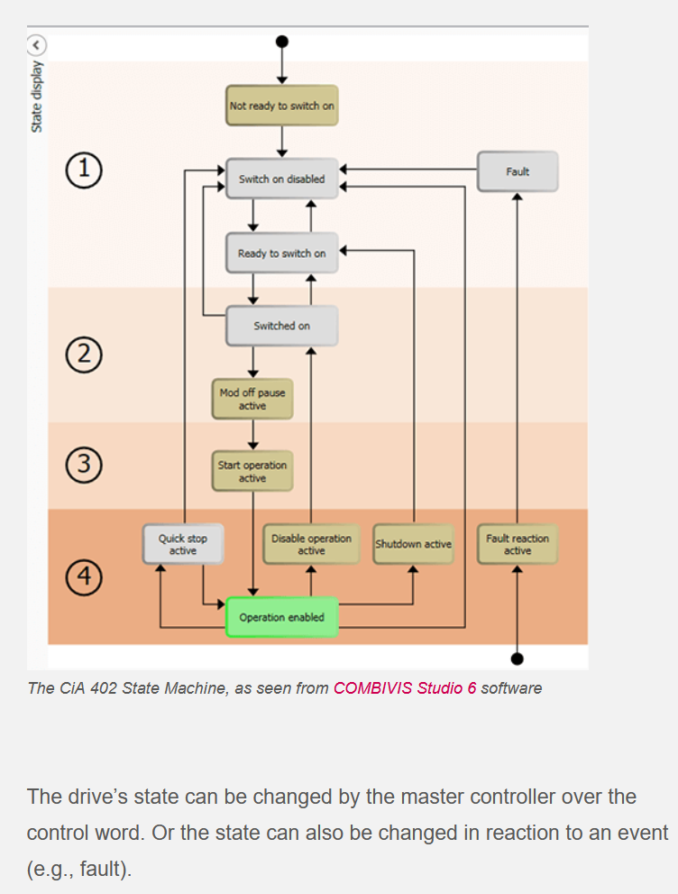
The cia402 component really only uses two states, disabled and op enabled, controlled by the enable pin.
Either transition to and stay in disabled mode, or transition to and stay in op enabled mode.
When in op enabled state, you can switch between the different operation modes. Anyway.
Is there no message in the syslog when you have a mismatch between pdos? I would have expected something there.
they have problem with the rotary position feedback. Could there be a general way? Save the position, and later
create an offset to add to the position feedback. Sounds like that could work.
The point I wanted to make about cia402 state machine was that the device decides the state,
the cia402 component can only react and ask for a change of state.
The cia402 component really only uses two states, disabled and op enabled, controlled by the enable pin.
Either transition to and stay in disabled mode, or transition to and stay in op enabled mode.
When in op enabled state, you can switch between the different operation modes. Anyway.
Is there no message in the syslog when you have a mismatch between pdos? I would have expected something there.
- timo
- timo
25 Jan 2026 14:57 - 25 Jan 2026 15:19
Replied by timo on topic Best controll board for LinuxCNC
Best controll board for LinuxCNC
Category: General LinuxCNC Questions
As I understood open loop drivers and motors are existing and are kept in the system. (for the time beeing) ")
It is probably difficult to answer the question. What makes a controller better (best)?
It is probably difficult to answer the question. What makes a controller better (best)?
- cheap? (two parallel ports (PCIe cards) in old office PC)
- least amount of re-wiring? (existing parallel port machine?)
- cheaper? (but not a bit of documentation) ( FPGA cards of unknown origin)
- Is wasted time cheaper than money spent?
- easy to set up? ( pnc config)
- upgradable? (linear scales, tool changer, rigid tapping, closed loop positioning, linear motors)
I used an old parallel port machine, changing form mach3 to LinuxCNC was 90% figuring the "charge pump" out (no re-wiring, all in software), then the computer quit service and the replacement had no parallel port. (a 10$ PCIe card fixed that).
Having problems to get an encoder running a Mesa card (6i25 with daughter card) went into the machine. (solving the spindle encoder issue) (it still is a Frankenstein mixed Mesa and Parallel port).
Greetings Timo
p.s. the UC300ETH is that working with linuxcnc? Some older threads stated it does not work.
forum.linuxcnc.org/27-driver-boards/2982...moothstepper-to-mesa
- Hakan
- Hakan
24 Jan 2026 13:16 - 24 Jan 2026 13:18
Replied by Hakan on topic Lichuan 4 axis stepper need help-
Lichuan 4 axis stepper need help-
Category: EtherCAT
Well, I think it follows the state diagram up to the point of operation
But for sure it isn't perfect. I have noticed multiple homing components around even if I don't use it myself.
Can you add support for PV (Profile Velocity) while you are at it? I made a quick fix for that.
PV is suitable for spindle mode.
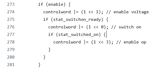
You should be able to transition states manually, in halshow for example, using controlword and check statusword.
Maybe that can give a clue to why it seems so grumpy.
But for sure it isn't perfect. I have noticed multiple homing components around even if I don't use it myself.
Can you add support for PV (Profile Velocity) while you are at it? I made a quick fix for that.
PV is suitable for spindle mode.
You should be able to transition states manually, in halshow for example, using controlword and check statusword.
Maybe that can give a clue to why it seems so grumpy.
Time to create page: 0.658 seconds