Search Results (Searched for: )
- besriworld
- besriworld
02 Sep 2024 14:06
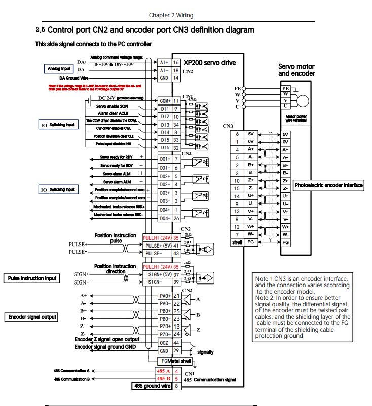
Replied by besriworld on topic Chinese Servo Drive Calibration XP200
Chinese Servo Drive Calibration XP200
Category: Milling Machines
- mighty_mick

02 Sep 2024 12:44
Optimizing Tool Paths or Generated G-code was created by mighty_mick
Optimizing Tool Paths or Generated G-code
Category: Post Processors
- Aciera

02 Sep 2024 12:18
Replied by Aciera on topic Sliders for overrides in gmoccapy
Sliders for overrides in gmoccapy
Category: General LinuxCNC Questions
- Walkahz
- Walkahz
02 Sep 2024 11:40
Chinese Servo Drive Calibration XP200 was created by Walkahz
Chinese Servo Drive Calibration XP200
Category: Milling Machines

- Aciera
02 Sep 2024 11:40
Replied by Aciera on topic Modbus VFD startup delay?
Modbus VFD startup delay?
Category: Basic Configuration
- Aciera
02 Sep 2024 10:59
Replied by Aciera on topic Understanding Source Files and Debugging
Understanding Source Files and Debugging
Category: General LinuxCNC Questions
- zz912

02 Sep 2024 10:31
Replied by zz912 on topic Pendant with 7i73: question with analog inputs
Pendant with 7i73: question with analog inputs
Category: Driver Boards
- Str8jacket
- Str8jacket
02 Sep 2024 10:00

- seyad
- seyad
02 Sep 2024 09:25
Understanding Source Files and Debugging was created by seyad
Understanding Source Files and Debugging
Category: General LinuxCNC Questions
- MennilTossFlykune
- MennilTossFlykune
02 Sep 2024 08:33
Replied by MennilTossFlykune on topic Modbus VFD startup delay?
Modbus VFD startup delay?
Category: Basic Configuration
- Aciera
02 Sep 2024 08:08
Replied by Aciera on topic Modbus VFD startup delay?
Modbus VFD startup delay?
Category: Basic Configuration
- Creative25
- Creative25
02 Sep 2024 07:30 - 07 Sep 2024 11:09
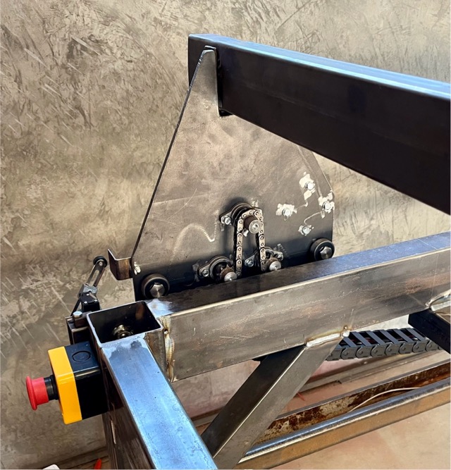
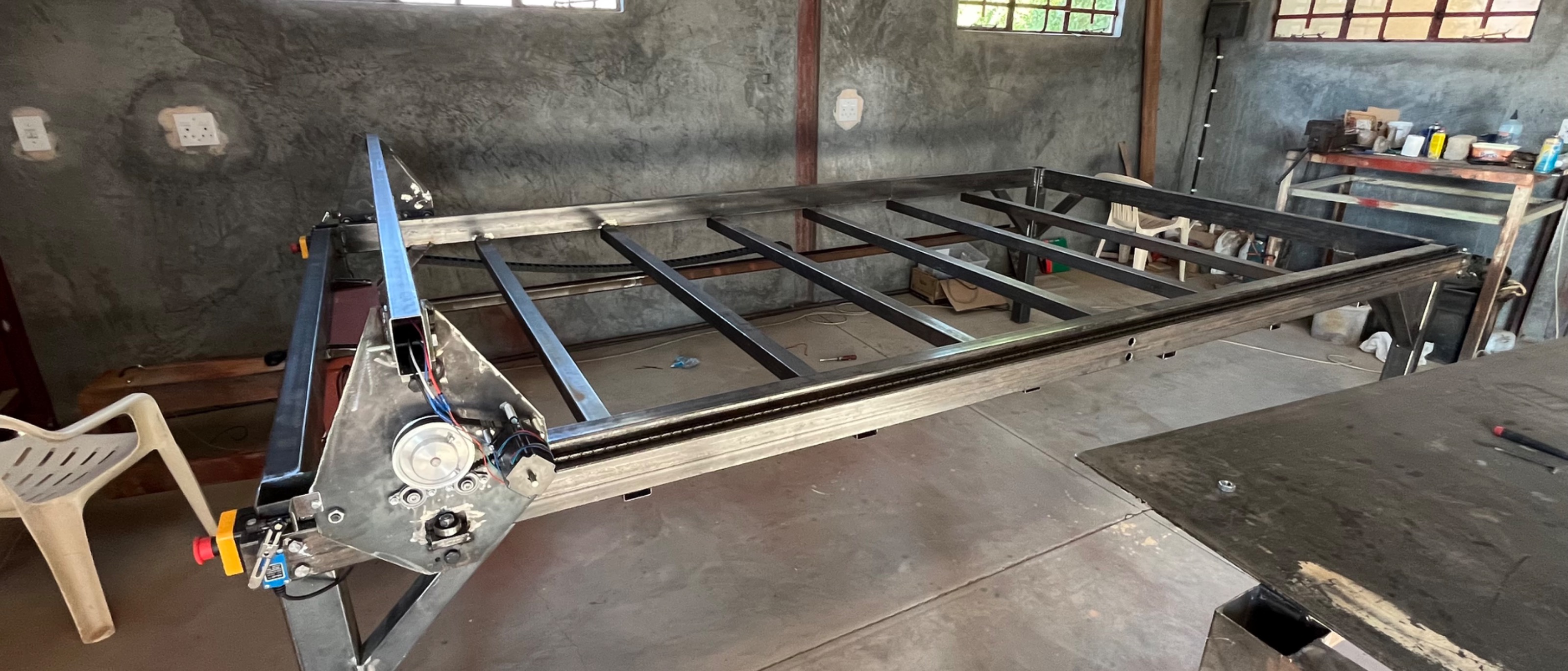
Replied by Creative25 on topic Building a chain driven Plasma table.
Building a chain driven Plasma table.
Category: General LinuxCNC Questions
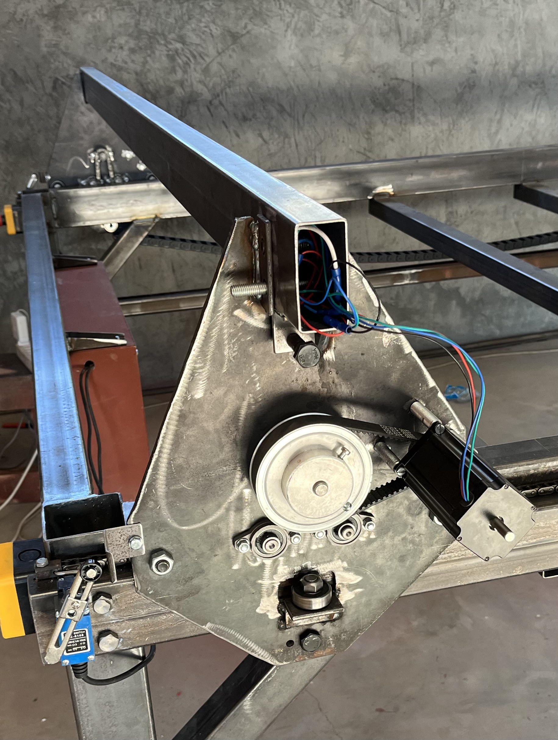
- Creative25
- Creative25
02 Sep 2024 07:29
Replied by Creative25 on topic Building a chain driven Plasma table.
Building a chain driven Plasma table.
Category: General LinuxCNC Questions
- Creative25
- Creative25
02 Sep 2024 07:15
Replied by Creative25 on topic Building a chain driven Plasma table.
Building a chain driven Plasma table.
Category: General LinuxCNC Questions
- MennilTossFlykune
- MennilTossFlykune
02 Sep 2024 07:09
Replied by MennilTossFlykune on topic Modbus VFD startup delay?
Modbus VFD startup delay?
Category: Basic Configuration
Time to create page: 0.506 seconds