Search Results (Searched for: )
- Donb9261

06 Jul 2024 14:55
- Project_Hopeless

06 Jul 2024 14:44
Replied by Project_Hopeless on topic 7i96s Board Firmware
7i96s Board Firmware
Category: Driver Boards

- blazini36
- blazini36
06 Jul 2024 13:51
- Aciera

06 Jul 2024 13:42 - 06 Jul 2024 13:58
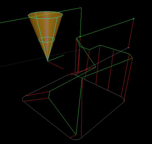
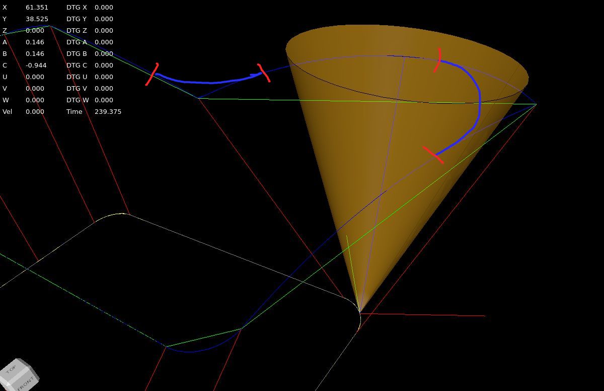
Replied by Aciera on topic Trajectory Planner using Ruckig Lib
Trajectory Planner using Ruckig Lib
Category: General LinuxCNC Questions
- garthnoakes
- garthnoakes
06 Jul 2024 13:14
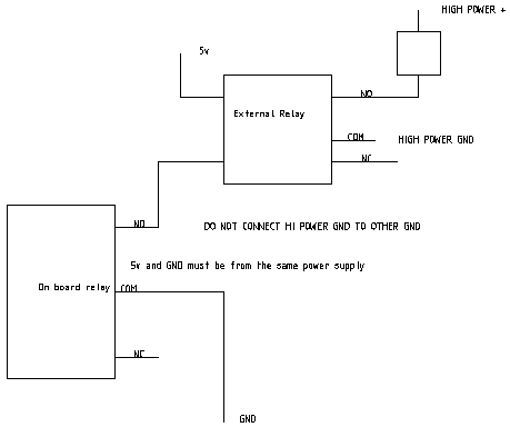
Replied by garthnoakes on topic Driving relay using NO, COM and or NC
Driving relay using NO, COM and or NC
Category: Driver Boards
- Cant do this anymore bye all

06 Jul 2024 13:12 - 06 Jul 2024 13:26
Replied by Cant do this anymore bye all on topic Driving relay using NO, COM and or NC
Driving relay using NO, COM and or NC
Category: Driver Boards
- garthnoakes
- garthnoakes
06 Jul 2024 13:12
Replied by garthnoakes on topic Driving relay using NO, COM and or NC
Driving relay using NO, COM and or NC
Category: Driver Boards
- Cant do this anymore bye all
06 Jul 2024 13:04
Replied by Cant do this anymore bye all on topic Driving relay using NO, COM and or NC
Driving relay using NO, COM and or NC
Category: Driver Boards
- Altenthaler1988
- Altenthaler1988
06 Jul 2024 12:52
Replied by Altenthaler1988 on topic qtplasmac "torch not showing"
qtplasmac "torch not showing"
Category: Plasmac
- garthnoakes
- garthnoakes
06 Jul 2024 12:51
Replied by garthnoakes on topic Driving relay using NO, COM and or NC
Driving relay using NO, COM and or NC
Category: Driver Boards
- Grotius

06 Jul 2024 12:50
Replied by Grotius on topic Trajectory Planner using Ruckig Lib
Trajectory Planner using Ruckig Lib
Category: General LinuxCNC Questions
- Cant do this anymore bye all
06 Jul 2024 12:34 - 06 Jul 2024 12:37
Replied by Cant do this anymore bye all on topic Driving relay using NO, COM and or NC
Driving relay using NO, COM and or NC
Category: Driver Boards
- Grotius
06 Jul 2024 12:33
Replied by Grotius on topic Trajectory Planner using Ruckig Lib
Trajectory Planner using Ruckig Lib
Category: General LinuxCNC Questions
- Robbbbbb
- Robbbbbb
06 Jul 2024 12:16
- garthnoakes
- garthnoakes
06 Jul 2024 12:16
Replied by garthnoakes on topic Driving relay using NO, COM and or NC
Driving relay using NO, COM and or NC
Category: Driver Boards
Time to create page: 0.512 seconds