Search Results (Searched for: )
- Adam Maszynotwór
07 Apr 2026 19:19
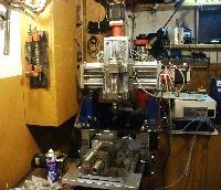
ATC lathe - Clasic Ladder, Stream Deck, Remap M6 My setup was created by Adam Maszynotwór
ATC lathe - Clasic Ladder, Stream Deck, Remap M6 My setup
Category: Advanced Configuration
")
- slowpoke
- slowpoke
07 Apr 2026 18:42 - 08 Apr 2026 10:50
Replied by slowpoke on topic Spindle encoder configuration (with G76 threading command and Mesa 7i96s)
Spindle encoder configuration (with G76 threading command and Mesa 7i96s)
Category: HAL
- Muecke

07 Apr 2026 18:03
")
- andrax

07 Apr 2026 17:53
Replied by andrax on topic Beckhoff BK1120 + KL modules on Linuxcnc
Beckhoff BK1120 + KL modules on Linuxcnc
Category: EtherCAT
- Atsu
- Atsu
07 Apr 2026 17:49
- Todd Zuercher

07 Apr 2026 17:41 - 07 Apr 2026 17:43
Replied by Todd Zuercher on topic Homing To Index Following Error
Homing To Index Following Error
Category: Advanced Configuration
- Nkbhvid
- Nkbhvid
07 Apr 2026 17:25
Beckhoff BK1120 + KL modules on Linuxcnc was created by Nkbhvid
Beckhoff BK1120 + KL modules on Linuxcnc
Category: EtherCAT
- eraserhd
- eraserhd
07 Apr 2026 17:25
- Todd Zuercher
07 Apr 2026 17:21
Replied by Todd Zuercher on topic Homing To Index Following Error
Homing To Index Following Error
Category: Advanced Configuration
- SteepLearningCurve
- SteepLearningCurve
07 Apr 2026 16:37
Replied by SteepLearningCurve on topic Issue getting XYYZ gantry to home (using 7i92t with 7i76u)
Issue getting XYYZ gantry to home (using 7i92t with 7i76u)
Category: Basic Configuration
- andrax
07 Apr 2026 16:29
- tommylight

07 Apr 2026 16:12
Replied by tommylight on topic Rotary axis backplot — centre of rotation not following WCS offset
Rotary axis backplot — centre of rotation not following WCS offset
Category: General LinuxCNC Questions
- PCW

07 Apr 2026 15:36
Replied by PCW on topic Homing To Index Following Error
Homing To Index Following Error
Category: Advanced Configuration
- Todd Zuercher
07 Apr 2026 15:17
Replied by Todd Zuercher on topic Homing To Index Following Error
Homing To Index Following Error
Category: Advanced Configuration
- grandixximo

07 Apr 2026 14:44
Replied by grandixximo on topic Ethercat random jitter fix
Ethercat random jitter fix
Category: EtherCAT
Time to create page: 0.651 seconds