Search Results (Searched for: )
- tar_san
- tar_san
02 Feb 2026 18:32
Replied by tar_san on topic How to let M101 turn on multiple digital output and wait digital input
How to let M101 turn on multiple digital output and wait digital input
Category: G&M Codes
- tommylight

02 Feb 2026 18:23
Replied by tommylight on topic Raspberry pi 5 freze
Raspberry pi 5 freze
Category: General LinuxCNC Questions
- krille
- krille
02 Feb 2026 18:08
Raspberry pi 5 freze was created by krille
Raspberry pi 5 freze
Category: General LinuxCNC Questions
- opw
- opw
02 Feb 2026 15:19
Simple G7x Profile editor for Linuxcnc/Axis was created by opw
Simple G7x Profile editor for Linuxcnc/Axis
Category: AXIS

- djdelorie
- djdelorie
02 Feb 2026 15:05
Replied by djdelorie on topic Where should linux cnc tool offsets be stored?
Where should linux cnc tool offsets be stored?
Category: General LinuxCNC Questions
")
- djdelorie
- djdelorie
02 Feb 2026 15:04
Replied by djdelorie on topic Where should linux cnc tool offsets be stored?
Where should linux cnc tool offsets be stored?
Category: General LinuxCNC Questions
- ruediger123
- ruediger123
02 Feb 2026 14:35
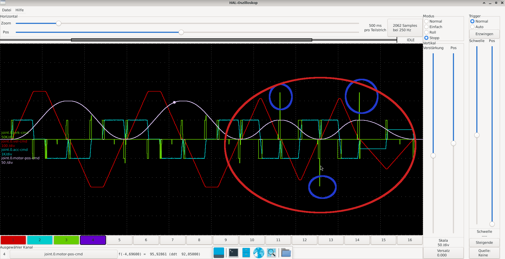
Replied by ruediger123 on topic LinuxCNC S-Curve Accelerations
LinuxCNC S-Curve Accelerations
Category: General LinuxCNC Questions
- Hakan
- Hakan
02 Feb 2026 14:20
- tommylight
02 Feb 2026 13:50
- Todd Zuercher

02 Feb 2026 13:01
Replied by Todd Zuercher on topic Need help selecting a Spindle and VFD
Need help selecting a Spindle and VFD
Category: Milling Machines
- Todd Zuercher
02 Feb 2026 12:49
Replied by Todd Zuercher on topic Maxnc15CL Motor timing help
Maxnc15CL Motor timing help
Category: General LinuxCNC Questions
- rodw

02 Feb 2026 10:03 - 02 Feb 2026 10:05

- rodw
02 Feb 2026 09:54
Replied by rodw on topic Where should linux cnc tool offsets be stored?
Where should linux cnc tool offsets be stored?
Category: General LinuxCNC Questions
- Ismacr63
- Ismacr63
02 Feb 2026 09:48
- jrc
- jrc
02 Feb 2026 09:13
Replied by jrc on topic Step By Step Help Needed . EL8 Leadshine to PI 5
Step By Step Help Needed . EL8 Leadshine to PI 5
Category: EtherCAT
Time to create page: 2.124 seconds