NativeCAM is Features renamed
- Gene1934
- Offline
- Elite Member
-

Less
More
- Posts: 174
- Thank you received: 13
17 Dec 2017 20:09 #103240
by Gene1934
Cheers, Gene Heskett
--
"There are four boxes to be used in defense of liberty:
soap, ballot, jury, and ammo. Please use in that order."
-Ed Howdershelt (Author)
Genes Web page <geneslinuxbox.net:6309/gene>
Replied by Gene1934 on topic NativeCAM is Features renamed
Reading upthread, I just found the zip is busted, si I'll try the git clone. Trying to run the txt installer from the zip, in the config directory of the lcnc 2.8.0-pre, I got this response from the script when it was to access my ini file:
gene@GO704:~/linuxcnc/configs/GO704fast$ ncam --ini=GO704Fast.ini --catalog=mill
Traceback (most recent call last):
File "/usr/bin/ncam", line 5150, in <module>
verify_ini(os.path.abspath(ini), catalog, in_tab)
File "/usr/bin/ncam", line 4952, in verify_ini
with open(fname, 'r') as b :
IOError: [Errno 2] No such file or directory: '/home/gene/linuxcnc/configs/GO704fast/GO704Fast.ini'
And that IS the exact path to that .ini file. ??? Is there a fix, or do I blow this whole tree away and git-clone it?
Cheers, Gene1934
Cheers, Gene Heskett
--
"There are four boxes to be used in defense of liberty:
soap, ballot, jury, and ammo. Please use in that order."
-Ed Howdershelt (Author)
Genes Web page <geneslinuxbox.net:6309/gene>
Please Log in or Create an account to join the conversation.
- kjacobs
- Offline
- Junior Member
-

Less
More
- Posts: 23
- Thank you received: 3
18 Dec 2017 07:58 #103274
by kjacobs
Replied by kjacobs on topic NativeCAM is Features renamed
Hi Fern,
Regards,
Karl
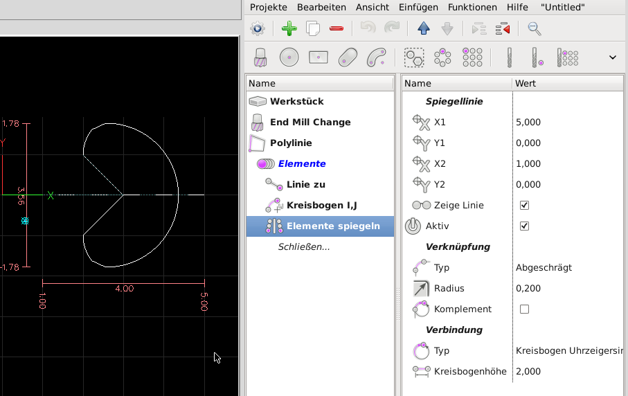
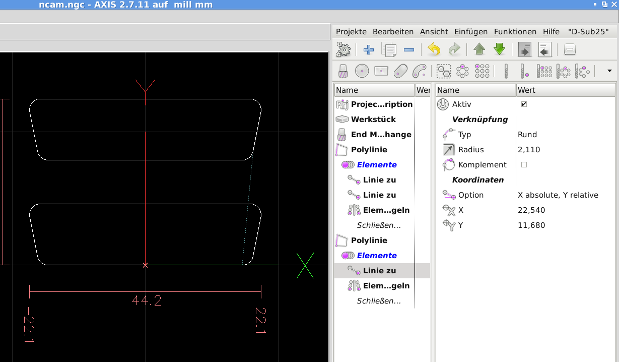
Earlier I did exactly that but did not see an effect. What I missed is that the "Mirror items" component comes up de-activated per default. I changed that behaviour in cfg/mill/polyline-mirror-i.cfg. Thanks for your help.. In your case what you need is "Elemente spiegeln" (Mirror items) and place it after the elements you want to miror like this image.
Regards,
Karl
Please Log in or Create an account to join the conversation.
- FernV
-
 Topic Author
- Offline
- Platinum Member
-

Less
More
- Posts: 457
- Thank you received: 124
18 Dec 2017 18:34 - 18 Dec 2017 18:39 #103301
by FernV
Having active by default made it very confusing in many case, wondering what was happening. I think re-ordering parameters with defining the mirror line first then activate would help.
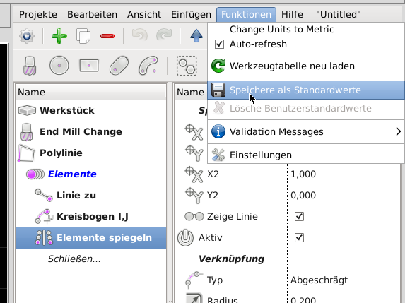
Instead of changing cfg/mill/polyline-mirror-i.cfg, right click and save values as your custom defaults after you changed parameters in ncam. Those defaults will be read every time you use cfg/mill/polyline-mirror-i.cfg or any other cfg file.
Fern
P.S. in next release, when not active, no parameters will be visible (except active of course)
Replied by FernV on topic NativeCAM is Features renamed
Hi Fern,
Earlier I did exactly that but did not see an effect. What I missed is that the "Mirror items" component comes up de-activated per default. I changed that behaviour in cfg/mill/polyline-mirror-i.cfg. In your case what you need is "Elemente spiegeln" (Mirror items) and place it after the elements you want to miror like this image.
Having active by default made it very confusing in many case, wondering what was happening. I think re-ordering parameters with defining the mirror line first then activate would help.
Instead of changing cfg/mill/polyline-mirror-i.cfg, right click and save values as your custom defaults after you changed parameters in ncam. Those defaults will be read every time you use cfg/mill/polyline-mirror-i.cfg or any other cfg file.
Fern
P.S. in next release, when not active, no parameters will be visible (except active of course)
Last edit: 18 Dec 2017 18:39 by FernV.
The following user(s) said Thank You: kjacobs
Please Log in or Create an account to join the conversation.
- Gene1934
- Offline
- Elite Member
-
Less
More
- Posts: 174
- Thank you received: 13
18 Dec 2017 19:31 #103305
by Gene1934
Cheers, Gene Heskett
--
"There are four boxes to be used in defense of liberty:
soap, ballot, jury, and ammo. Please use in that order."
-Ed Howdershelt (Author)
Genes Web page <geneslinuxbox.net:6309/gene>
Replied by Gene1934 on topic NativeCAM is Features renamed
How do I enable this backplot I see in the first snapshot above? Or what do I need to install and configure as the case may be?
Thanks & Cheers, Gene1934
Thanks & Cheers, Gene1934
Cheers, Gene Heskett
--
"There are four boxes to be used in defense of liberty:
soap, ballot, jury, and ammo. Please use in that order."
-Ed Howdershelt (Author)
Genes Web page <geneslinuxbox.net:6309/gene>
Please Log in or Create an account to join the conversation.
- kjacobs
- Offline
- Junior Member
-
Less
More
- Posts: 23
- Thank you received: 3
18 Dec 2017 22:17 #103317
by kjacobs
Replied by kjacobs on topic NativeCAM is Features renamed
Gene,
all I did was follow message # 94274 of this forum, then type ncam -h to get instructions how to embed into your ini-file.
Updates to new versions of NativeCAM after that are as easy as sudo apt-get update & sudo apt-get install nativecam
See forum.linuxcnc.org/40-subroutines-and-ng...w?limitstart=0#94274
Karl
Please Log in or Create an account to join the conversation.
- Gene1934
- Offline
- Elite Member
-
Less
More
- Posts: 174
- Thank you received: 13
18 Dec 2017 22:43 #103320
by Gene1934
Cheers, Gene Heskett
--
"There are four boxes to be used in defense of liberty:
soap, ballot, jury, and ammo. Please use in that order."
-Ed Howdershelt (Author)
Genes Web page <geneslinuxbox.net:6309/gene>
Replied by Gene1934 on topic NativeCAM is Features renamed
I did try it, it was added to the right edge of the lcnc screen. Viewing by an ssh login, now I go start it from its own keyboard and leave it running for a few hours as I have to go and play cook for some dinner now. Might even leave it cutting air for that wheel.
Thanks & Cheers to both of you.
Gene1934
Thanks & Cheers to both of you.
Gene1934
Cheers, Gene Heskett
--
"There are four boxes to be used in defense of liberty:
soap, ballot, jury, and ammo. Please use in that order."
-Ed Howdershelt (Author)
Genes Web page <geneslinuxbox.net:6309/gene>
Please Log in or Create an account to join the conversation.
- FernV
-
Topic Author
- Offline
- Platinum Member
-
Less
More
- Posts: 457
- Thank you received: 124
19 Dec 2017 14:17 #103343
by FernV
Replied by FernV on topic NativeCAM is Features renamed
Hi Karl
This is also for anyone wanting to learn more about polyline.
I created a demo on simpler and simplest ways to create a DSub cutout. Information is in the Project description
Fern
This is also for anyone wanting to learn more about polyline.
I created a demo on simpler and simplest ways to create a DSub cutout. Information is in the Project description
Fern
Please Log in or Create an account to join the conversation.
- kjacobs
- Offline
- Junior Member
-
Less
More
- Posts: 23
- Thank you received: 3
19 Dec 2017 21:43 #103364
by kjacobs
Replied by kjacobs on topic NativeCAM is Features renamed
Hi Fern,
that is very instructive, thank you! I should have thought earlier about the link types for polylines,which shows that I am still on the steep part of the learning curve. What I do not quite get though is how you arrived at the radii and lengths of the polylines to get to the same final dimensions as my "complicated" version that I constructed from published drawings (www.norcomp.net/dsub-panel-cutouts). I used the 3.35mm radius given there for example and you use 3.327mm, and also I do not find a relation of the line length of the bottom straight part to the value (C) in the drawing. Actually, if I shift my "complicated" version by 50.8+3.335mm to compare the versions, there is a tiny height difference, but the radii look identical on the backplot. (I used the shift of -3.335mm to have the centerline at y0 which makes it a bit simpler to offset the cutout to a given position). So in short, my question is how to arrive at given dimensions with the "simplest" version.
Cheers,
Karl
Please Log in or Create an account to join the conversation.
- FernV
-
Topic Author
- Offline
- Platinum Member
-
Less
More
- Posts: 457
- Thank you received: 124
20 Dec 2017 00:56 - 20 Dec 2017 04:30 #103371
by FernV
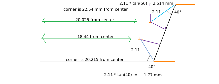
You just need to find the intersections of the straight lines and then apply the indicated radius
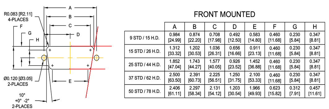
I used the dimensions for a 25 pins and the calculation is simple as you can see. If it is not clear enough, ask for more details.
P.S. lower angle is NOT 40° but 50°
Regards
Fern
Replied by FernV on topic NativeCAM is Features renamed
In fact, I just superposed just to get about the same dimensions but here how to do it, it is just a little trigonometry... how you arrived at the radii and lengths of the polylines to get to the same final
You just need to find the intersections of the straight lines and then apply the indicated radius
I used the dimensions for a 25 pins and the calculation is simple as you can see. If it is not clear enough, ask for more details.
P.S. lower angle is NOT 40° but 50°
Regards
Fern
Last edit: 20 Dec 2017 04:30 by FernV.
Please Log in or Create an account to join the conversation.
- kjacobs
- Offline
- Junior Member
-
Less
More
- Posts: 23
- Thank you received: 3
20 Dec 2017 04:54 - 20 Dec 2017 09:40 #103380
by kjacobs
Replied by kjacobs on topic NativeCAM is Features renamed
Hi Fern,
understood! On the other hand, now that "simplest" does not mean "least brainpower" anymore, I'd rather call your construction method "ingenious" from now on") Thanks for your explanations, and maybe you should arrange a new section in the forum containing a standard part library for NativeCAM for everyone to contribute, unless there is one already and I missed it.
Thanks for your explanations, and maybe you should arrange a new section in the forum containing a standard part library for NativeCAM for everyone to contribute, unless there is one already and I missed it.
For the final version of the D-Sub 25 the two mounting holes would have to be added, which is of course trivial.
Happy Holidays,
Karl
Edit: I did find a small quirk with your last version. If you try to set tool compensation to "left", there is an error concerning the entry move (3mm or 2mm cutter dia). If you flip it in X (long side on the bottom), it works, but it looks to me like part of the entry move is outside of the contour and would spoil the cutout. I think that does not happen in my "complicated" version because it starts to cut at the straight section. I am sure you will show me again what I missed...
understood! On the other hand, now that "simplest" does not mean "least brainpower" anymore, I'd rather call your construction method "ingenious" from now on
Thanks for your explanations, and maybe you should arrange a new section in the forum containing a standard part library for NativeCAM for everyone to contribute, unless there is one already and I missed it.For the final version of the D-Sub 25 the two mounting holes would have to be added, which is of course trivial.
Happy Holidays,
Karl
Edit: I did find a small quirk with your last version. If you try to set tool compensation to "left", there is an error concerning the entry move (3mm or 2mm cutter dia). If you flip it in X (long side on the bottom), it works, but it looks to me like part of the entry move is outside of the contour and would spoil the cutout. I think that does not happen in my "complicated" version because it starts to cut at the straight section. I am sure you will show me again what I missed...
Last edit: 20 Dec 2017 09:40 by kjacobs. Reason: Addition
Please Log in or Create an account to join the conversation.
Time to create page: 0.229 seconds