Another plasma component...
- phillc54
-
 Topic Author
- Offline
- Platinum Member
-

- Posts: 5711
- Thank you received: 2100
Not sure if this would workThe gcode for the buttons are defined in the ini file. I get soft limit issues on loading sheets so I've been meaning to hard code the position to be a bit less than the actual maximum (eg 1mm less)
BUTTON_2_CODE = G53 G0 Z[[AXIS_Z]MAX_LIMIT - nn] (with nn being the distance delow max height)
I intend to revisit probing later, I am not completely happy with it...When testing probing on different thickness of steel, I wondered if safe height and probe height would be better based off the material rather than the Z min limit? Then again I guess if these values are set for the maximum material that the table will cut, then there is no chance to select the wrong material and have the torch crash into it.
The plasmac component only starts doing it's thing when it receives a torch on signal so at the moment it does expect that the user has everything in position ready to go. It may be possible in future to do something about that...If I start the gcode program and the torch is below safe height, it rapids to the first cut coordinates without first raising to safe height, after the cut is finished it raises to safe height rapids back to x0 y0 then appears to drop the torch down to prob height. Should z not always raise to safe height before a rapid? Then raise to max limit at the end of the program?
That I am not sure about, Dewey Garrett the author of 'external offsets' would be the person to ask. It probably wouldn't hurt though.One question, in the Z Axis section should the stepgen_maxaccel and stepgen_maxvel be double the values they are in the joint section?
EDIT1:
There is no mention of these settings in the [AXIS_<letter>] section of the ini file, only in the [JOINT_<num>] section so my guess is they are not required in the [AXIS_<letter>] section.
Are these stepgen settings even required for hardware stepgens or only for the software stepgen component?
EDIT2:
Darren, your config is looking for these settings in the [AXIS_<letter>] section:
setp   hm2_5i25.0.stepgen.00.dirsetup        [AXIS_X]DIRSETUP
setp   hm2_5i25.0.stepgen.00.dirhold         [AXIS_X]DIRHOLD
setp   hm2_5i25.0.stepgen.00.steplen         [AXIS_X]STEPLEN
setp   hm2_5i25.0.stepgen.00.stepspace       [AXIS_X]STEPSPACE
setp   hm2_5i25.0.stepgen.00.position-scale  [AXIS_X]STEP_SCALE
setp   hm2_5i25.0.stepgen.00.maxaccel        [AXIS_X]STEPGEN_MAXACCEL
setp hm2_5i25.0.stepgen.00.maxvel [AXIS_X]STEPGEN_MAXVELsetp hm2_5i25.0.stepgen.00.dirsetup [JOINT_0]DIRSETUP
setp hm2_5i25.0.stepgen.00.dirhold [JOINT_0]DIRHOLD
setp hm2_5i25.0.stepgen.00.steplen [JOINT_0]STEPLEN
setp hm2_5i25.0.stepgen.00.stepspace [JOINT_0]STEPSPACE
setp hm2_5i25.0.stepgen.00.position-scale [JOINT_0]STEP_SCALE
setp hm2_5i25.0.stepgen.00.maxaccel [JOINT_0]STEPGEN_MAXACCEL
setp hm2_5i25.0.stepgen.00.maxvel [JOINT_0]STEPGEN_MAXVELCheers, Phill.
Please Log in or Create an account to join the conversation.
- phillc54
-
Topic Author
- Offline
- Platinum Member
-
- Posts: 5711
- Thank you received: 2100
I don't. Photos I could and should do but I can't do videos yet as doing this configuration has stalled my build.Do you have any pictures / video to show of your build?
Safe height is first calculated as the height above the material at a successful probe. If THC is enabled then safe height is updated to account for any rise in Z so that it ends up being calculated as the height above the highest point encountered.I also wold like to see the safe height and probe height to be set above the materials height
Probe height is the height above the Z minimum, as posted above I will revisit that.
Cheers, Phill.
Please Log in or Create an account to join the conversation.
- phillc54
-
Topic Author
- Offline
- Platinum Member
-
- Posts: 5711
- Thank you received: 2100
Up to now I have been thinking a tool change was only to change cut parameters.
I now think that sometimes it is required to actually change a nozzle as well as parameters.
IF TRUE:
- how do you guys do a nozzle change now? (the manual toolchange popup?)
- we need to be able to differentiate between a simple parameter change and a more complex nozzle and parameters change.
- we would need some sort of nozzle identification in the plasmac_tool_table, I had thought of Amps but then there a different nozzle types with the same current rating.
- how many different nozzle types per user would we need to account for?
- is there something standard in CAM tool tables that we could pick out?
- am I trying to do too much?
- life got harder...

IF FALSE:
- life is good...
")
I have got a prototype file converter working for you SheetCam users to copy SheetCam tool tables to plasmac format.
Does SheetCam always keep their tool table values as metric format?
If anyone has different format tool tables then I would be happy to have a crack at a converter after (if) we get tool handling sorted.
Cheers, Phill.
Sorry for the string of posts, the brain is a tad slow today...
Please Log in or Create an account to join the conversation.
- islander261
- Offline
- Platinum Member
-
- Posts: 757
- Thank you received: 216
Just got home from the seasons first market on the mainland. I have updated my Plasmac config to your latest release and will test in the morning.
The SheetCam tool table I sent you actually sorts the tools by material, thickness and cutting current (nozzle size), that is one reason there are so many entries. People wanting to use this in a job shop setting will want every combination called out like the file I posted. I use one nozzle size almost exclusively and rarely use another. After doing this for 9 years now I still have my original packages of the higher current nozzles I bought when I started. Needless to say I have never heard of anyone changing the nozzle sizes between cuts on a work piece but I could be wrong ( a M6 and a manual tool change will still handle this).
Thanks again for all the hard work. The Plasmac branch works far better than anything else I have used. I may seem picky but really all I am doing is trying to push the (your) branch to be the best available solution for plasma cutting.
I actually found changing over to the Plasmac branch pretty easy. Of course I was starting from a working LinuxCNC driven plasma cutter. Including macro buttons for a test probe (check the actual physical height of a probe) and tests cuts of say 150mm (6") or so on each axis will be a big help to newbies, they may not know it but those are the first two things you need to do before cutting an actual part file.
John
Please Log in or Create an account to join the conversation.
- phillc54
-
Topic Author
- Offline
- Platinum Member
-
- Posts: 5711
- Thank you received: 2100
I am guessing that some regular nozzles and some fine cut nozzles have the same amperage. I also assume that there are more than these two types. To do a real tool change there would need to be a way of distinguishing between them.The SheetCam tool table I sent you actually sorts the tools by material, thickness and cutting current (nozzle size)
I would be extremely happy if that is the case.Needless to say I have never heard of anyone changing the nozzle sizes between cuts on a work piece
Unfortunately the work I have done on tool handling stops this working as normal (it has a remapped T word) but with individual nozzle assignment I coulda M6 and a manual tool change will still handle this
No, not at all, you need to be as I know nothing about cutting. I would love to achieve that result as well.I may seem picky but really all I am doing is trying to push the (your) branch to be the best available solution for plasma cutting
If you think any of your macros or modifications should be included I would be happy to put them in.
Cheers, Phill.
Please Log in or Create an account to join the conversation.
- phillc54
-
Topic Author
- Offline
- Platinum Member
-
- Posts: 5711
- Thank you received: 2100
This ONLY applies to the Gmoccapy config and does not affect the plasmac component.
There are quite number of changes as listed below.
The standard LinuxCNC tool table is bypassed and a plasmac specific tool table is used. The tool table name is derived from [EMC]MACHINE in the in file, so a machine named METRIC_PLASMAC would have a tool table named metric_plasmac_tool.tbl. This file could be created by renaming your existing .mat file and modifying to suit.
The additional parameters are:
TOOL_NUMBER_ - this is now the section header rather than material name
NAME - this is the old header without []
KERF_WIDTH - this is passed to the #<kerf_width> parameter for cutter compensation
THC - this enables/disables THC on a per tool basis. 0 = disable, 1 = enable
All other parameters are as they were.
Tool numbers do not need to be consecutive nor do they need to be in numerical order. The maximum allowed tool number is 99999 as I believe this is the largest LinuxCNC will accept.
Tool handling is done by remapping the T word, so a M6 Tn will load the parameters associated with tool number n.
So if you don't want to use this feature then you can comment out:
REMAP = T prolog=plasmac_tool_prolog ngc=plasmac_tool epilog=plasmac_tool_epilogWhen a tool is changed it only changes the cut parameter, LinuxCNC knows nothing of the tool or its offsets.
To use cutter compensation you will need to use G41.1, G42.1 and G40 with the new global parameter #<kerf_width> like so:
G41.1 D#<kerf_width> for left of programmed path
G42.1 D#<kerf_width> for right of programmed path
G40 to turn compensation off
Tools can be selected manually with the Tool number spin button but this does not load the new #<kerf_width> value, to do this you need to do a M6 Tn via MDI.
The supplied metric and imperial *_plasmac_tool.tbl files are not meant for cutting, they were just use for testing as are the metric and imperial *_tool_change.ngc files in the nc_files/plasmac directory.
I hope I haven't forgotten anything or broken too much.
Cheers, Phill.
File changes:
MODIFIED:
configs/sim/gmoccapy/plasmac/imperial_plasmac.ini
configs/sim/gmoccapy/plasmac/imperial_plasmac.mat
configs/sim/gmoccapy/plasmac/metric_plasmac.ini
configs/sim/gmoccapy/plasmac/metric_plasmac.mat
configs/sim/gmoccapy/plasmac/plasmac_feed.ngc
configs/sim/gmoccapy/plasmac/plasmac_run.glade
configs/sim/gmoccapy/plasmac/plasmac_run.hal
configs/sim/gmoccapy/plasmac/plasmac_run.py
configs/sim/gmoccapy/plasmac/python/remap.py
DELETED:
configs/sim/gmoccapy/plasmac/imperial_plasmac.mat
configs/sim/gmoccapy/plasmac/imperial_tool.tbl
configs/sim/gmoccapy/plasmac/metric_plasmac.mat
configs/sim/gmoccapy/plasmac/metric_tool.tbl
ADDED:
configs/sim/gmoccapy/plasmac/imperial_plasmac_tool.tbl
configs/sim/gmoccapy/plasmac/metric_plasmac_tool.tbl
configs/sim/gmoccapy/plasmac/plasmac_tool.ngc
configs/sim/gmoccapy/plasmac/tool.tbl
configs/sim/gmoccapy/plasmac/toolverter.py
nc_files/plasmac/imperial_tool_change.ngc
nc_files/plasmac/metric_tool_change.ngc
Please Log in or Create an account to join the conversation.
- rodw
-

- Offline
- Platinum Member
-
- Posts: 12032
- Thank you received: 4106
You'll be please about that as I have about 7 tips I can use.
If I'm lazy, I can avoid changing out a nozzle by changing the selected material at a different amperage.
I did think about scanning the cut charts page diagrams of the consumables that show the part numbers and including a link to the image in the materials file. But all 40 amps mild steel would display the one image regardless of thickness. If there was an image included in a cut chart entry, you could unhide a button and display the image in a popup so you knew what parts you had to install.
Please Log in or Create an account to join the conversation.
- phillc54
-
Topic Author
- Offline
- Platinum Member
-
- Posts: 5711
- Thank you received: 2100
There is weird behaviour in Gmoccapy with the F word display. It seems that it displays the FeedRate for the segment after the one that is cutting. If you display velocity that is correct.
There is a python program named toolverter.py in the Gmoccapy folder. That will convert tools from SheetCam to plasmac. It only converts ones known as Plasmatools.
Cheers, Phill.
Please Log in or Create an account to join the conversation.
- rodw
-
- Offline
- Platinum Member
-
- Posts: 12032
- Thank you received: 4106
This is what I had in mind. Include an image file name like this for a given entry in the tool table
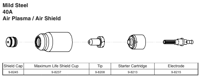
This would be very useful.
Attachments:
Please Log in or Create an account to join the conversation.
- rodw
-
- Offline
- Platinum Member
-
- Posts: 12032
- Thank you received: 4106
I had a quick look at the plasmac.comp source and it was not immediately apparent. There was a THC enable pin but I assumed it is hooked to the GUI.
Please Log in or Create an account to join the conversation.