Downdraft design questions
- txtrone
-
 Topic Author
- Offline
- Platinum Member
-

Less
More
- Posts: 384
- Thank you received: 106
26 Dec 2020 05:36 #193212
by txtrone
Yes, motion is running, I can move the gantry around with the keyboard using Axis gui. I still need to do some fine tuning of course, but all the directions are correct.
I have not wired my proximity sensors yet, the table still has the mechanical home and limit switches on it... and I have not bothered to wire them up since they will be replaced.
All I lack on solenoid wiring is landing on the Mesa card, I will check everything with a meter and then connect one at a time like you suggest. If I can wait on home and limits and keep working on the solenoids AND I can operate the solenoids using Axis gui, then I will get that setup first. That will be a pretty big day for me to see those blast gates in operation!
Replied by txtrone on topic Downdraft design questions
I think I would get the motion side up and running if you have not already.
Then I would install the ddraft component and connect the outputs to them...
Yes, motion is running, I can move the gantry around with the keyboard using Axis gui. I still need to do some fine tuning of course, but all the directions are correct.
I have not wired my proximity sensors yet, the table still has the mechanical home and limit switches on it... and I have not bothered to wire them up since they will be replaced.
All I lack on solenoid wiring is landing on the Mesa card, I will check everything with a meter and then connect one at a time like you suggest. If I can wait on home and limits and keep working on the solenoids AND I can operate the solenoids using Axis gui, then I will get that setup first. That will be a pretty big day for me to see those blast gates in operation!
The following user(s) said Thank You: rodw
Please Log in or Create an account to join the conversation.
- tommylight
-

- Offline
- Moderator
-

Less
More
- Posts: 21747
- Thank you received: 7433
26 Dec 2020 12:31 #193223
by tommylight
Replied by tommylight on topic Downdraft design questions
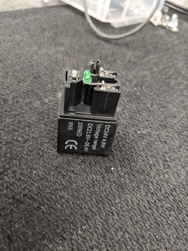
The valves are 110V ! ")
What current do the valves require ?
What current do the valves require ?
Please Log in or Create an account to join the conversation.
- Aciera
-

- Offline
- Administrator
-

Less
More
- Posts: 4755
- Thank you received: 2135
26 Dec 2020 13:18 #193228
by Aciera
Which valves ?
Replied by Aciera on topic Downdraft design questions
The valves are 110V !
Which valves ?
Please Log in or Create an account to join the conversation.
- tommylight
-
- Offline
- Moderator
-
Less
More
- Posts: 21747
- Thank you received: 7433
26 Dec 2020 13:53 - 26 Dec 2020 13:54 #193229
by tommylight
They are inverted.
Replied by tommylight on topic Downdraft design questions
On the drawings ..
The valves are 110V !
Which valves ?
They are inverted.
Last edit: 26 Dec 2020 13:54 by tommylight. Reason: more info
Please Log in or Create an account to join the conversation.
- txtrone
-
Topic Author
- Offline
- Platinum Member
-
Less
More
- Posts: 384
- Thank you received: 106
26 Dec 2020 14:24 #193233
by txtrone
haha ... I missed that on the image I used in the schematic. I will correct it at some point.
The actual valves I am using are 24v and require 0.2A
Replied by txtrone on topic Downdraft design questions
The valves are 110V !
What current do the valves require ?
haha ... I missed that on the image I used in the schematic. I will correct it at some point.
The actual valves I am using are 24v and require 0.2A
Please Log in or Create an account to join the conversation.
- tommylight
-
- Offline
- Moderator
-
Less
More
- Posts: 21747
- Thank you received: 7433
26 Dec 2020 14:53 #193234
by tommylight
Replied by tommylight on topic Downdraft design questions
That should do just fine.
Please Log in or Create an account to join the conversation.
- thefabricator03
-

- Visitor
-

26 Dec 2020 22:11 #193251
by thefabricator03
Replied by thefabricator03 on topic Downdraft design questions
What program do you use to do your schematic drawings?
Please Log in or Create an account to join the conversation.
- txtrone
-
Topic Author
- Offline
- Platinum Member
-
Less
More
- Posts: 384
- Thank you received: 106
27 Dec 2020 21:50 #193314
by txtrone
DIYLC - Do It Yourself Layout Creator ... several people on a tube amp forum were using it and I find it pretty easy to work with for freeware.
bancika.github.io/diy-layout-creator/
diy-fever.com/software/diylc/
Replied by txtrone on topic Downdraft design questions
What program do you use to do your schematic drawings?
DIYLC - Do It Yourself Layout Creator ... several people on a tube amp forum were using it and I find it pretty easy to work with for freeware.
bancika.github.io/diy-layout-creator/
diy-fever.com/software/diylc/
The following user(s) said Thank You: tommylight
Please Log in or Create an account to join the conversation.
- txtrone
-
Topic Author
- Offline
- Platinum Member
-
Less
More
- Posts: 384
- Thank you received: 106
28 Dec 2020 00:09 #193324
by txtrone
Replied by txtrone on topic Downdraft design questions
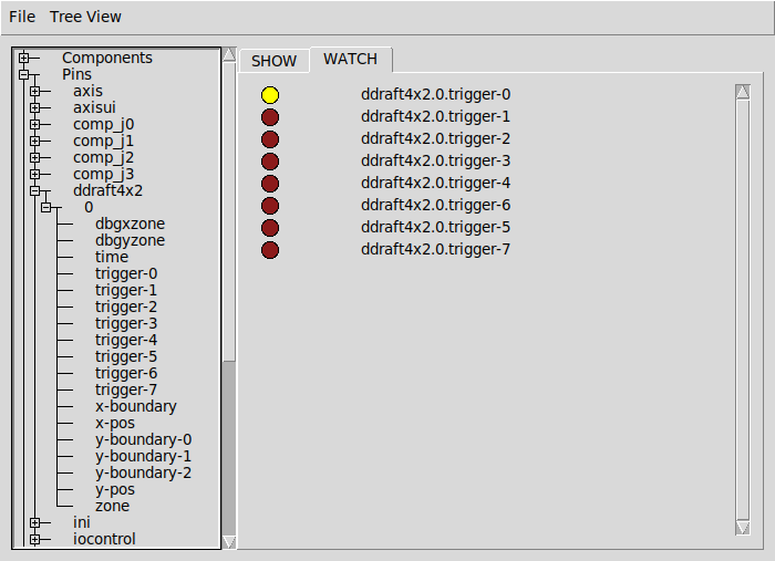
Where does this code go? Also, are these two lines of code specific to one zone? ie: will I need eight sections like this, one for each zone?I generally would do it like this:
net zone0 <= ddraft4x2.0.trigger-0
net zone0 =>  hm2_7i76e.0.7i76.0.0.output-00
net zone0 <=ddraft4x2.0.trigger-0
net zone0 => hm2_7i76e.0.7i76.0.0.output-00I am sure this will make more sense the once I grasp the first part.So if you wish to change the zone boundaries you can edit ddraft4x2.hal file to change them
Please Log in or Create an account to join the conversation.
- rodw
-

- Away
- Platinum Member
-
Less
More
- Posts: 12041
- Thank you received: 4109
28 Dec 2020 01:36 #193332
by rodw
Replied by rodw on topic Downdraft design questions
Yes, you need 8 pins like that using the pin names from the component, like I created. zone0,zone1, .... zone7
Some people will connect pins using one line but I always like to do it on two lines.
The first line creates a signal. Eg solders a wire to the downdraft output pin if it were hardware.
The second line connects the other end of the wire to something. In this case a 7i76e output pin.
You have to decide which hardware pins you are using.
The following user(s) said Thank You: txtrone
Please Log in or Create an account to join the conversation.
Moderators: snowgoer540
Time to create page: 1.671 seconds