Downdraft design questions
- tommylight
-

- Offline
- Moderator
-

Less
More
- Posts: 21747
- Thank you received: 7433
21 Dec 2020 21:23 #192713
by tommylight
Replied by tommylight on topic Downdraft design questions
That should do, but i also ground everything in the control box, so i use the extra motor wire to ground a part of the machine after bearings, meaning each moving part of the machine has a ground so it does not rely on the bearings to be grounded.
And in general, the signal wiring should be grounded only on the electronics side, not on both sides.
And in general, the signal wiring should be grounded only on the electronics side, not on both sides.
The following user(s) said Thank You: txtrone
Please Log in or Create an account to join the conversation.
- txtrone
-
 Topic Author
- Offline
- Platinum Member
-

Less
More
- Posts: 384
- Thank you received: 106
21 Dec 2020 21:44 #192724
by txtrone
Replied by txtrone on topic Downdraft design questions
That makes perfect sense. I appreciate it!
The following user(s) said Thank You: tommylight
Please Log in or Create an account to join the conversation.
- txtrone
-
Topic Author
- Offline
- Platinum Member
-
Less
More
- Posts: 384
- Thank you received: 106
22 Dec 2020 21:45 #192873
by txtrone
This part requires the installation of Plasmac, correct?
I am still getting my base machine setup, as the instructions are pretty clear about getting the base machine dead-nuts before proceeding to Plasmac.
Replied by txtrone on topic Downdraft design questions
To go live, copy ddraft4x2.hal to your config folder and edit your ini file in a text editor (I use Geany!) and add it to the [HAL] section
This part requires the installation of Plasmac, correct?
I am still getting my base machine setup, as the instructions are pretty clear about getting the base machine dead-nuts before proceeding to Plasmac.
Please Log in or Create an account to join the conversation.
- rodw
-

- Offline
- Platinum Member
-
Less
More
- Posts: 12041
- Thank you received: 4109
22 Dec 2020 22:32 #192885
by rodw
You can do that now and plasmac should leave it alone. Note I uploaded a revised sketch of how to wire in the solenoids on your other wiring thread. The band on the diode points towards the mesa output. Pretty much any diode will do IN4004/IN4007 etc are as cheap as chips.
Replied by rodw on topic Downdraft design questions
To go live, copy ddraft4x2.hal to your config folder and edit your ini file in a text editor (I use Geany!) and add it to the [HAL] section
This part requires the installation of Plasmac, correct?
I am still getting my base machine setup, as the instructions are pretty clear about getting the base machine dead-nuts before proceeding to Plasmac.
You can do that now and plasmac should leave it alone. Note I uploaded a revised sketch of how to wire in the solenoids on your other wiring thread. The band on the diode points towards the mesa output. Pretty much any diode will do IN4004/IN4007 etc are as cheap as chips.
The following user(s) said Thank You: txtrone
Please Log in or Create an account to join the conversation.
- txtrone
-
Topic Author
- Offline
- Platinum Member
-
Less
More
- Posts: 384
- Thank you received: 106
23 Dec 2020 01:28 #192908
by txtrone
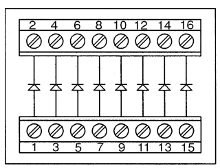
On this type of series diode module, how would you connect the negative wire from the bus and the output from the Mesa card? Or does the output from the Mesa card attach to one side of the diode and continue thru to the solenoid? For instance, would the output from the Mesa card for solenoid #1 connect to terminal #1 on the diode block, then 'continue' out through terminal #2.... while the negative wire from the 2x bus connects direct to the solenoid?
Replied by txtrone on topic Downdraft design questions
The band on the diode points towards the mesa output. Pretty much any diode will do IN4004/IN4007
On this type of series diode module, how would you connect the negative wire from the bus and the output from the Mesa card? Or does the output from the Mesa card attach to one side of the diode and continue thru to the solenoid? For instance, would the output from the Mesa card for solenoid #1 connect to terminal #1 on the diode block, then 'continue' out through terminal #2.... while the negative wire from the 2x bus connects direct to the solenoid?
Attachments:
Please Log in or Create an account to join the conversation.
- txtrone
-
Topic Author
- Offline
- Platinum Member
-
Less
More
- Posts: 384
- Thank you received: 106
23 Dec 2020 14:38 - 23 Dec 2020 14:42 #192962
by txtrone
Replied by txtrone on topic Downdraft design questions
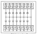
After a little more research, I am thinking I need the time with a common anode. Something like this:
Attachments:
Last edit: 23 Dec 2020 14:42 by txtrone. Reason: I uploaded the wrong diagram the first time
Please Log in or Create an account to join the conversation.
- tommylight
-
- Offline
- Moderator
-
Less
More
- Posts: 21747
- Thank you received: 7433
23 Dec 2020 15:36 #192973
by tommylight
Replied by tommylight on topic Downdraft design questions
That should be it for the non D versions of Mesa.
Preferably wait for PCW to confirm that.
Preferably wait for PCW to confirm that.
The following user(s) said Thank You: txtrone
Please Log in or Create an account to join the conversation.
- txtrone
-
Topic Author
- Offline
- Platinum Member
-
Less
More
- Posts: 384
- Thank you received: 106
23 Dec 2020 16:15 - 23 Dec 2020 16:16 #192982
by txtrone
Will do. I am just trying to round up material before the holidays... so I can work on it all next week.
I still can't wrap my head around where the diode needs to go.
ETA: I see you explanation in another thread. Let me make a quick schematic and post it up for verification.
Replied by txtrone on topic Downdraft design questions
That should be it for the non D versions of Mesa.
Preferably wait for PCW to confirm that.
Will do. I am just trying to round up material before the holidays... so I can work on it all next week.
I still can't wrap my head around where the diode needs to go.
ETA: I see you explanation in another thread. Let me make a quick schematic and post it up for verification.
Last edit: 23 Dec 2020 16:16 by txtrone.
Please Log in or Create an account to join the conversation.
- tommylight
-
- Offline
- Moderator
-
Less
More
- Posts: 21747
- Thank you received: 7433
23 Dec 2020 16:18 #192983
by tommylight
Replied by tommylight on topic Downdraft design questions
I wanted to quote and say i did reply to that, by the time i got my eyes on the screen i see the edit there! ")
Please Log in or Create an account to join the conversation.
- Aciera
-

- Offline
- Administrator
-

Less
More
- Posts: 4755
- Thank you received: 2135
23 Dec 2020 16:26 - 23 Dec 2020 16:29 #192985
by Aciera
Replied by Aciera on topic Downdraft design questions
The diode needs to go from the positive side of your solenoid inductor to the negative of your solenoid conductor with the "ring" pointing to the positive side.
The reason for this is that the moment you switch your solenoid off the magnetic field that was opening your pneumatic valve collapses and that changing magnetic field will induce a fairly large voltage in the solenoid inductor that can damage the drivers on the board. This induced voltage is inverted in polarity compared to the voltage you supply the inductor with so it will find a short circuit through the diode while your supply voltage will find the diode not conductive.
en.wikipedia.org/wiki/Flyback_diode
[edit]
Diode orientation:
electronics.stackexchange.com/questions/...al-diode-orientation
Last edit: 23 Dec 2020 16:29 by Aciera.
The following user(s) said Thank You: txtrone
Please Log in or Create an account to join the conversation.
Moderators: snowgoer540
Time to create page: 0.290 seconds