THC Velocity lock and void lock
- beefy
- Offline
- Elite Member
-

- Posts: 227
- Thank you received: 58
I don't think Linuxcnc has any problem reacting fast enough at 1 ms servo thread to manage any cutting condition, That lets the THC respond as fast as motion parameters change so the THC can be stopped more or less instantly (as far as Linuxcnc's view of the world.)
Following corrugated iron is well within plasmac's capabilities, its just that the maximum velocity of the Z axis determines the maximum XY velocity because the z axis must be able to follow the contour of the material at the cutting speed. The magic of plasmac, linuxcnc and external offsets will do the rest.
But yes, you are on the right track. There are many cut parameters that could be fine tuned if the system knows the material thickness. I guess it can make a guess at the material thickness based on the cut velocity but with a larger machine that has consumables to cut at 8-9 different amperages and do not communicate the amperage to the plasma controller its probably not possible.
I'll take your comments on board as a vote to include material thickness in the cut files.
Rod,
I think you may have mis-understood what I was saying.
At no point was I ever saying Plasmac could not react fast enough or was not capable of cutting corrugated. On the contrary, my point was that for Void Lock to activate, if the THC (including the mechanics too) is indeed fast enough to correct the voltage (drive the torch down) when passing over a void, you won't get the necessary voltage "spike" that causes the THC to lock. I also theorised that potentially, a fast THC reaction could even cause the torch to dive and crash into the material because Void Lock may not happen. So dampening the THC reaction on slower cuts could be a potential solution.
Of course when I'm talking about fast THC reaction, the assumption is the mechanics of the Z are physically capable of carrying out the THC moves. Without that a fast THC reaction in software is meaningless.
As for your last paragraph my thoughts are that XY feedrate is the main factor as opposed to material thickness. Yes feedrates generally go down as material gets thicker but for any given thickness, feedrates can vary based on nozzle size and corresponding amperage. And the system always knows the commanded feedrate so no guessing.
Keith
Please Log in or Create an account to join the conversation.
- rodw
-

- Offline
- Platinum Member
-

- Posts: 11697
- Thank you received: 3953
The transition at a kerf cross is not instantaneous because the arc "stretches" as it still makes contact with the edge of the void.
Because of the LCNC architecture we can only "see" changes at the servo thread frequency (typically 1000 times per second) and we can only alter the torch height at that frequency too. So a kerf crossing algorithm is able to be as responsive as changes in torch height can be. At one stage, Pre-plasmac, I did play around with a slower thread just for THC but I abandoned it..... I guess that says something.
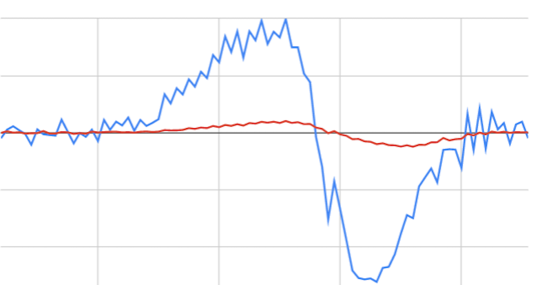
So what we have is this ever increasing arc length due to the distance from the edge which will eventually extinguish if some replacement material is not found (eg the other side of a kerf). The advantage of introducing a moving average is that it provides a greater and more stable platform anchored by prior results. Think of the moving average as being a diving board hanging out over the void. It takes quite a number of readings before the average can be influenced by the arc voltage at this very millisecond before the diving board curls upwards. So this makes a much better reference point to compare the arc voltage increase as it crosses the void.
This image from the plasma primer shows the diving board effect.
Ref: linuxcnc.org/docs/devel/html/plasma/plas...#_void_kerf_crossing
But what it also shows that I don't think Pedro is accounting for is a rapid dip below the diving board as the kerf is crossed before the arc stabilises on the other side of the kerf. You must wait until the arc stabilises before reenabling the THC so there are a number of states the data transitions through during the void crossing.
In my limited testing, I got good results from this and I did not see much of a difference between material thicknesses. I ended up with some fairly convoluted code and I had a slight dive if you ran off a sheet I wanted to address. By this time I had pretty well discovered the states that we needed to track (I had no idea what they were when I started) so I started to rewrite my component as a a state machine. But I broke it and then got busy so I never got back to getting the state machine working.
The thing about tracking dv/dt is that its a much more responsive indicator of the void behaviour. Essentially though its measuring the same thing as torch voltage becasues dt = 1 millisecond in Linuxcnc's servo thread.
I will say, I did nail the moving average part which is quite complex to do in an interrupt service routine without resorting to loops. This code is used in my ohmic3.comp that floats around this forum if you want to have a play.
EDIT: What a mess this new forum is when trying to edit a post. anything after the image is deleted when you press edit.
Please Log in or Create an account to join the conversation.
- phillc54
-

- Offline
- Platinum Member
-

- Posts: 5711
- Thank you received: 2093
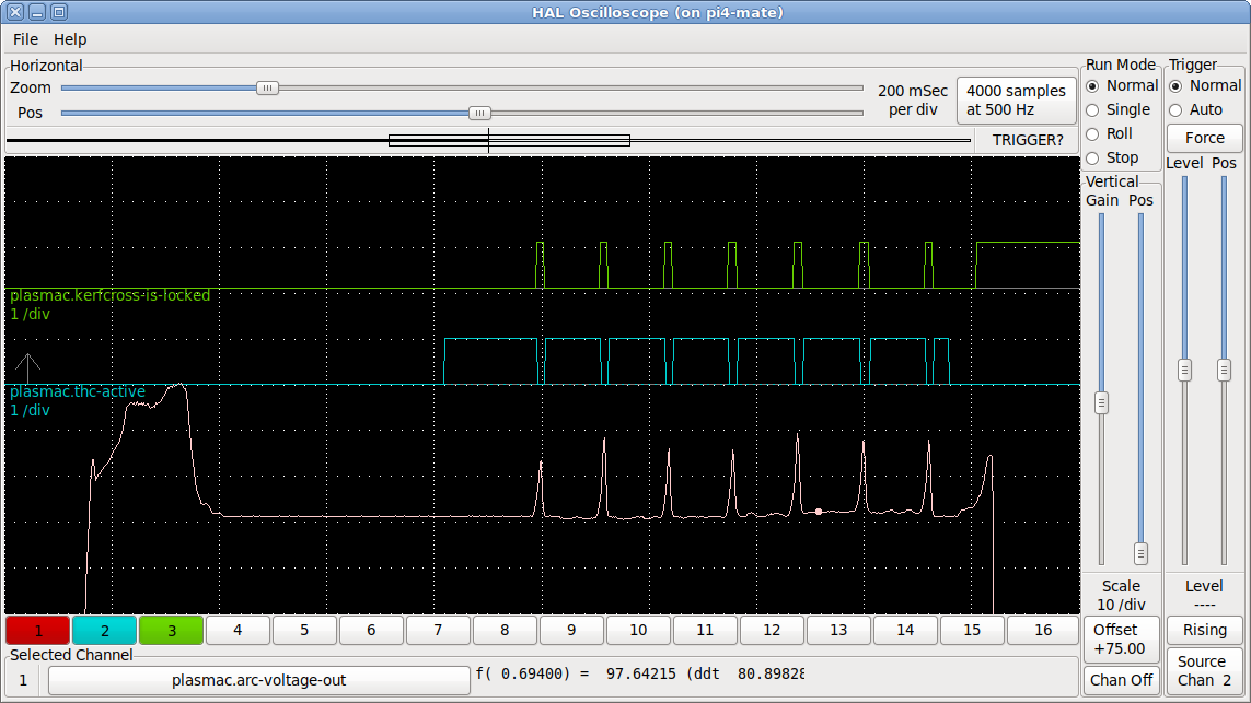
Regarding the image you show, my last testing of kerf crossing didn't show up any dips in the arc voltage like that plot.
forum.linuxcnc.org/plasmac/37886-void-lo...tion?start=30#169039
Crikey that was over a year ago, time flies when your having fun...
Attachments:
Please Log in or Create an account to join the conversation.
- rodw
-

- Offline
- Platinum Member
-

- Posts: 11697
- Thank you received: 3953
A year ago!I don't see any point in moving average. You already know what the target voltage is either from the Auto Volts calculation or from the Cut Volts from the material file. The target voltage is the one you should be trying to maintain so that should be the base for any calculations.
Regarding the image you show, my last testing of kerf crossing didn't show up any dips in the arc voltage like that plot.
Crikey that was over a year ago, time flies when your having fun...
That plot in the primer was done back in 2018!
Its from halscope data massaged in a spreadsheet so it is not particularly high resolution
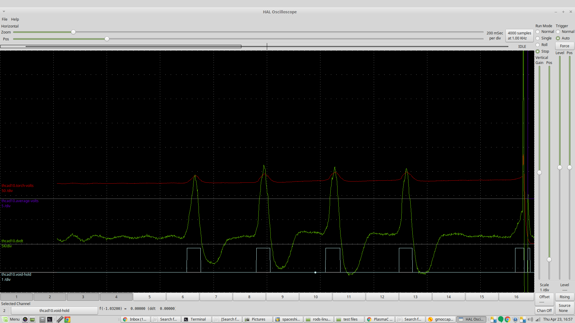
The reason why your plot differs to what I shared is that you are plotting arc voltage not dv/dt
This is what it looks like in halscope
Ref: forum.linuxcnc.org/plasmac/37886-void-lo...stion?start=0#165191
The moving average is not used directly. Instead its used as to calculate dv/dt
dvdt = (tvolts - avgvolts)/fperiod; // Calculate change in volts for this servo cycle.Clearly some people saw there was a point in calculating a moving average and dv/dt because they registered a patent over the technique which they milked for 20 years. It provides a much more sensitive indicator to a void crossing event.. Something that Pedro is finding difficult to achieve with the Plasmac algorithm.
Please Log in or Create an account to join the conversation.
- phillc54
-

- Offline
- Platinum Member
-

- Posts: 5711
- Thank you received: 2093
Maybe a bit text on the image may have helped.The reason why your plot differs to what I shared is that you are plotting arc voltage not dv/dt
This is what it looks like in halscope
I also don't see the benefit in calculating the actual dv/dt value. You then need to set whatever you are comparing it to as an equivalent type of value.The moving average is not used directly. Instead its used as to calculate dv/dt
dvdt = (tvolts - avgvolts)/fperiod; // Calculate change in volts for this servo cycle.
where torch volts = tvolts and avgvolts = moving average
We know we measure every cycle so why not just use tvolts - avgvolts and compare that result to a voltage value each cycle?
So how is it a more sensitive indicator than using the target voltage?Clearly some people saw there was a point in calculating a moving average and dv/dt because they registered a patent over the technique which they milked for 20 years. It provides a much more sensitive indicator to a void crossing event.
Please Log in or Create an account to join the conversation.
- rodw
-

- Offline
- Platinum Member
-

- Posts: 11697
- Thank you received: 3953
Well, the experts said
So how is it a more sensitive indicator than using the target voltage?
Ref: patents.google.com/patent/US5866872Testing has demonstrated that the absolute values of measured arc voltage slopes generated during a kerf crossing tend to be at least an order of magnitude greater than those generated due to workpiece warpage. For example, kerf crossing slopes can range from about 100 volts/sec to about 1000 volts/sec; whereas, warpage slopes are generally much less than 100 volts/sec. In FIG. 3, the kerf crossing spike slope is about 720 volts/sec. The warpage slope is about 14 volts/sec. Accordingly, kerf crossings and similar discontinuities can be reliably detected and accommodated readily with little chance of improperly overriding standoff control.
Please Log in or Create an account to join the conversation.
- phillc54
-

- Offline
- Platinum Member
-

- Posts: 5711
- Thank you received: 2093
A quick glance doesn't seem answer my questions but hopefully when I read it fully tomorrow they will be answered.
I don't see moving average anywhere but it does seem that the magic number is 100 volts/sec.
It is interesting that they use 2ms which is what I ended up with as the default.
Please Log in or Create an account to join the conversation.
- rodw
-

- Offline
- Platinum Member
-

- Posts: 11697
- Thank you received: 3953
There is other research that showed that the arc voltage terminates on the material at the "anode spot" which fluctuates from the top of the material to the bottom. This results in a natural variation of voltage seen at the torch. So its useful to apply a moving average to smooth out this natural variation which we often dismiss a noise. But becasue dv/dt at a void is exponentially higher than the norm, the average does not slow down void detection in my experiments. It can detect a void in 2-3 milliseconds (servo cycles).A natural complement to any time series interpretation, a moving average can smooth out the noise of random outliers and emphasize long-term trends.
The hard part was to sense when to turn the THC back on. I see the experts cheated and just waited for 10 ms and tried again. at a maximum cut speed of 10240mm/min, the torch travels 17mm in that time. I found it was possible to detect when the kerf had been crossed, but it took a lot to understand the dv/dt behaviour to work out how to do this.
100 as a threshold is too low, at a guess somewhere between 1000 to 3000 possibly even as high as 6000 from my halscope plots. I think this threshold needs to vary with material thickness from what I've been told and what Pedro advised. It really needs testing from 2mm to 20mm thickness to understand that.
Please Log in or Create an account to join the conversation.
- phillc54
-

- Offline
- Platinum Member
-

- Posts: 5711
- Thank you received: 2093
Edit: Oops I submitted too quickly...
From the look of your plot it would be better to use the arc voltage plot then the calculated dv/dt plot.
Please Log in or Create an account to join the conversation.
- rodw
-

- Offline
- Platinum Member
-

- Posts: 11697
- Thank you received: 3953
I don't think thats a good example with all the oscillations. I did not enable the THC and the thc disable signal was doing nothing cos I valued my torch! I can't really remember what I had it set at when I went live. I did a lot of plots of normal cutting so I could watch the data to get my head around it before writing any void sensing code.6000 is a heck of a lot more than HT's 1000 upper value...
Edit: Oops I submitted too quickly...
From the look of your plot it would be better to use the arc voltage plot then the calculated dv/dt plot.
The number of readings to average is configurable. I think I used 100 which was 0.1 seconds worth
What makes you say voltage was better? With all the observations I did, I thought I could set a safe threshold with dv/dt but not on just voltage alone.
Here is what Juha my Finnish high def expert friend said...
I did not take speed into accountKerf Crossing:
Typically there are 3 ways that the CNCs deal with this. Do not mistake this with holes, see my "notes" for hole cutting.
One:
Same as you do, they take the cutting speed and reference that to the arc voltages rate of change. As your thickness range can be 1-150mm the speed has a significant effect and has to be used in the equation (like seems you do). This is the best way to do it and can with the right settings makes it nice. I think there is a patent about this so not everybody does it this way.
Two:
Simple but not so good. You have 2 voltage values that you set Kerf detect ON and Kerf detect OFF. One triggers the torch to lock the height and disable AVC and the other releases the lock. Lets assume your set arc voltage is 100V KD_ON 20 and KD_OFF 15. If the arc voltage reaches 120V (100+120), the height will lock. It will stay locked until it goes below 115 (100+15).
Very simple and avoids collision but is not nearly as good as option 1.
Three:
CAM handles it. So typically you don't cross kerfs intentionally so that it would matter (normally you just cross the kerf in the end and it does really affect cut quality). But for example in corner loops, multipass bevel etc. you might cross the kerf. 99% of the times you do this on a CAM so it will put height locks in those sections where the kerf will be crossed. CNC just has to lock/unlock based on G-codes.
Please Log in or Create an account to join the conversation.


