Rods "Spaceship" Scratch built Plasma Cutter build
- rodw
-
 Topic Author
- Offline
- Platinum Member
-

- Posts: 12032
- Thank you received: 4106
After a bunch of searching online - I found a few references to .004/volt. (what I have been using) And I think that falls pretty close to what you are finding...
Yes thats a number (equates to 0.1mm/volt or 10 volts per mm) often quoted by Jim Colt of Hypertherm who said
» Sat May 09, 2015 8:30 am
Most height controls accurately control arc voltage to plus or minus about 2-3 volts. For every volt you will see roughly a .004"(0.1mm) change in height (this varies a bit with thickness and power levels). Controlling the arc voltage tighter than this usually creates some oscillation in the z axis, which will show as striations (roughness) in the cut edge.
I think it is funny when THC manufacturers advertise .5 volts accuracy......because the arc voltage itself fluctuates more than this (due to the moving cathode attachment).....which means the height control will oscillate rapidly up/down to try to compensate. In all cases when the edge gets rough because of this oscillation, you need to slow down the z axis speed or deaden the THC reaction time, which ultimately loosens up the voltage deadband to at least the 2-3 volt range. In reality controlling to plus or minus 5 volts is ok on materials thicker than .125".
One of the overlooked components in a THC is the mechanical tightness as well as the lack of "overshoot" of the z axis lifter. A loose lifter requires that the voltage range (deadband) is loosened up, a lifter that does not instantly stop (braking) will do the same. The z axis lifter, properly designed will be the most costly part of any THC.
This is what is what the external offsets simulated torch works on (because of that statement). Of course it varies from torch to torch.The other parameter we discovered in testing is that the THCAD board has a rise time of 5 ms which in the sim equates to a lowpass of 70 Hz (I'm just quoting what Dewey told me after looking at some plots I did for him as I don't really understand that).
So after getting the lowpass component docs revised by BigJohnT so they are understandable, I've reconfigured the eoffsets simulated torch to be as close to my torch as possible. based on these two bits of empirical data we've uncovered. I did find that in real cutting the resulting tuning did not crash my torch.
The eoffset_pid component now includes a deadband following one of my suggestions but I have not found it helpful in my last testing. In the sims any more than 0.5 volts made it pretty unstable.
So hopefully the new coupling on my Z axis will address "mechanical tightness as well as the lack of "overshoot" of the z axis lifter" in the last paragraph above.
Please Log in or Create an account to join the conversation.
- Grotius
-

- Offline
- Platinum Member
-
- Posts: 2419
- Thank you received: 2348
Maybe a stupid question.
Your input voltage is controlled real time trough a mesa ad card. Is a mesa comp file doing the height interactions in real time to the externall offset branche?
Why this question. It looks like you are missing some interaction speed if i read your posts. Or am i wrong about that view?
Please Log in or Create an account to join the conversation.
- rodw
-
Topic Author
- Offline
- Platinum Member
-
- Posts: 12032
- Thank you received: 4106
Hi Rod,
Maybe a stupid question.
Your input voltage is controlled real time trough a mesa ad card. Is a mesa comp file doing the height interactions in real time to the externall offset branche?
Why this question. It looks like you are missing some interaction speed if i read your posts. Or am i wrong about that view?
No such thing as a stupid question. The Mesa THCAD-10 card receives a 16:1 divided voltage from the Everlast plasma's voltage divider. The THCAD is a voltage to frequency converter with an internal 0-10 volt range. each THCAD has been individually calibrated and frequencies at 0 volts and 10 volts is provided. The THCAD is attached to the encoder input on my Mesa 7i76e which reads the frequency count which is decoded in real time in HAL. You can do the maths in Hal but I wrote a component to do it.
The external offsets branch includes the eoffset_pid component which includes its own PID algorithm which takes the decoded voltage, compares it with the commanded voltage (which I sample at the end of the THC delay period) and applies an appropriate external offset count to the Z axis in real time. A sim is included in the external offsets branch to allows you to play with this. The theory is you should be able to configure the SIM parameters to reflect your hardware and thus allow tuning without cutting anything. This simulation approach is quite common in the PID tuning world.
The way that external offsets works is a percentage of the axis velocity and acceleration is devoted to the offsets. So using the external offsets actually reduces the operating speed of the machine. So while reserving say 20% of the velocity and acceleration to external offsets might be fine on a lathe turning a crankshaft lobe, we want all of the available speed available for external offsets for plasma Z axis control. If we try say 80% to offsets then touchoffs take forever.. . So how I manage this is that when setting up the Z axis, in the INI file, I double the velocity and acceleration settings and apply a ratio of 50%. eg. 200% x 50% = 100%. We can get away with this on a plasma machine as touchoff and THC are mutually exclusive and we have 100% of the velocity and acceleration available to the THC and also for touchoff.
So I think in answer to your question, yes, the eoffset_pid comp written by Dewey does the THC stuff and applies the offset in real time in the servo thread.
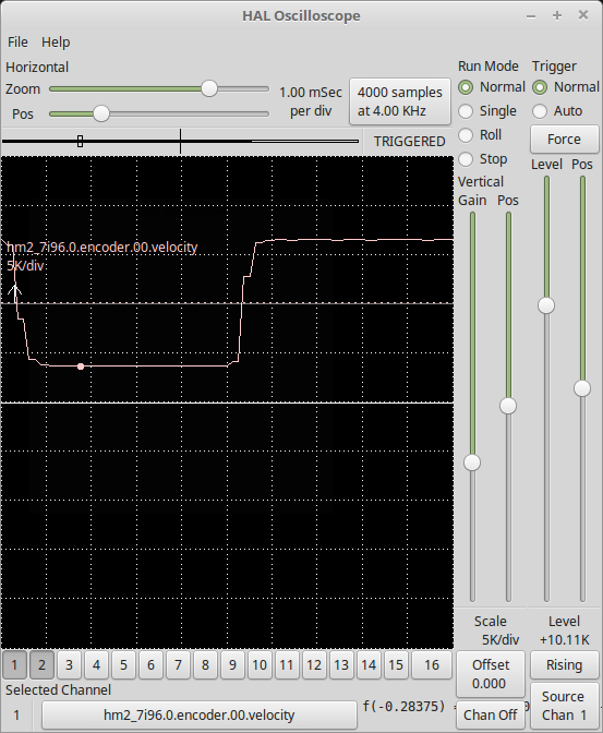
So back to my problem. No matter what I do, I get fairly regular oscillation around the set point so the hal plots of torch voltage look much like a sheet of corrugated iron. I am hoping that the new coupling has removed backlash from the system under the acceleration forces that are experienced. This backlash could be a source of overshoot and may be contributing to the oscillations I am experiencing. From what I've learnt, the original helix style coupling was overpowered by abot 3x it maximum backlash torque handling. So the proof will be in the cutting of the pudding!
Please Log in or Create an account to join the conversation.
- Grotius
-
- Offline
- Platinum Member
-
- Posts: 2419
- Thank you received: 2348
For the hardware :
1. Input 16:1 divided voltage from the Everlast plasma's voltage divider.
2. Input 0-10 volt range THCAD (Mesa)
For example, if you cut 45 amps with 117 volt = 0.0625 * 117 = 7.31 Volt
If you cut at 45 amps at 200 volt = 12.5 Volt (Mesa max is 10Volt in, smoke out of garage
 )
)Voltage divider must be set 1 to 50 if possible.
Then if you cut 350 volt : 7 volt input on mesa, quite good.
For the software :
1. Mesa has 0-10 Volt input, your self written comp file is calculating the real voltage out of this value.
2. You put this calculated input voltage value to the external offset branche z-axis value.
3. Your external offset branche will do the trick. It will react in speed on the ini z axis (2 values to set i remember)., and also your programmed distance, like 0.5mm for one step. If you are at m5. You say, delete offset and you are ready for the next cut.
4. If you use for example the thcud component there is a signal like at requested speed. Do you use this type of signal?
Please Log in or Create an account to join the conversation.
- tecno
-

- Offline
- Platinum Member
-
- Posts: 1850
- Thank you received: 127
Please Log in or Create an account to join the conversation.
- islander261
- Offline
- Platinum Member
-
- Posts: 757
- Thank you received: 216
Look at the THCAD manual on the Mesa site, all your questions will be answered.
On my system I take advantage of the within reason over voltage tolerance to have a full scale input arc voltage of about 180V .
John
Please Log in or Create an account to join the conversation.
- Grotius
-
- Offline
- Platinum Member
-
- Posts: 2419
- Thank you received: 2348
Before i posted my comment to Rod, i have read the pfd documentation of thcad mesa card.
My worries are only about the input voltage ratio. In my opinion a save input ratio is max 400 vdc.
Tecno is right. Use a hypertherm powermax 45 xp with internal voltage divider .
Optional order one with modbuss interface. I called hypertherm too late this day. But maybe rod is
better of with a powermax to make some progress. I have sayed before i sponsor, it depends on free shipping
to australia...
Please Log in or Create an account to join the conversation.
- robertspark
- Offline
- Platinum Member
-
- Posts: 915
- Thank you received: 216
Please Log in or Create an account to join the conversation.
- robertspark
- Offline
- Platinum Member
-
- Posts: 915
- Thank you received: 216
THCAD manual,
page 8
OPERATION
ISOLATION
The analog inputs on the THCAD are full floating with a 2500V RMS test rating (1 minute). This is a common mode rating. This is also specified as a 425V continuous peak rating with 50 year life.
Please Log in or Create an account to join the conversation.
- PCW
-

- Away
- Moderator
-

- Posts: 17990
- Thank you received: 5281
The THCAD10 has a maximum continuous input voltage rating of 500VDC so 12.5V or 500V will read as full scale but willIf you cut at 45 amps at 200 volt = 12.5 Volt (Mesa max is 10Volt in, smoke out of garage
not harm the THCAD-10
The other parameter we discovered in testing is that the THCAD board has a rise time of 5 ms which in the sim equates to a lowpass of 70 Hz (I'm just quoting what Dewey told me after looking at some plots I did for him as I don't really understand that).
The THCADs rise time is less then 0.5 ms. A 5 ms risetime would be detrimental to loop tuning. Of course any post direct data
filtering will affect the loop bandwidth.
Please Log in or Create an account to join the conversation.