Rods "Spaceship" Scratch built Plasma Cutter build
- rodw
-
 Topic Author
- Away
- Platinum Member
-

Less
More
- Posts: 12032
- Thank you received: 4104
12 Nov 2017 12:15 #101694
by rodw
Replied by rodw on topic Rods "Spaceship" Scratch built Plasma Cutter build
Thanks for that. I could not find it anywhere. The current metric version of the eoffsets branch calls an existing imperial subroutine and divides everything by 25.4.
Once I got down into the touch off routine everything was in imperial so my probe moves were too big for the Z axis to handle. eg 5mm became 5". I wanted to come up with a way to sense the units so the probing routine is better behaved so it can be fed back as an improvement.
I'm not ready to worry about the POST yet
And yes, expect an email that is already half written..
Please Log in or Create an account to join the conversation.
- rodw
-
Topic Author
- Away
- Platinum Member
-
Less
More
- Posts: 12032
- Thank you received: 4104
13 Nov 2017 22:25 - 13 Nov 2017 22:25 #101748
by rodw
Replied by rodw on topic Rods "Spaceship" Scratch built Plasma Cutter build
Well, I think I have finally got everything done to do live cutting with the external offsets default axis interface and control everything from gcode. I still want to think through my approach before cutting anything.
I wrote a component that samples torch voltage. it receives a digital input from a Timedelay on ArcOK ((currently set to 1.5 seconds) and the actual torch volts so when the timedelay fires, it samples the voltage, sets the commanded voltage and does the final enable to the eoffset_pid component to enable the torch height control. It took all of about 20 lines of code. Having seen how stable the volts are when cutting, I don't think there is much point doing any averaging when taking this sample so its a oneshot approach. At worst, it will differ by 0.2 volts or so based on what I've seen.
I'm also setting the cornerlock hold in gcode. eoffset_pid expects a velocity here but in practice, it is easier to think of percentages of the feed rate (eg. hold THC when velocity falls to 80% of programmed feed rate). This seems to work nicely. This is the bit I need to think through. In my gmoccapy config, I do all this in Hal from screen variables. To make this all seamless, I think it would be nicer to just set everything in a Sheetcam POST.
I'm hoping that starting the PID control right on the actual voltage will make a big difference to PID but we'll see what happens in the next day or so.
Last edit: 13 Nov 2017 22:25 by rodw.
The following user(s) said Thank You: tommylight
Please Log in or Create an account to join the conversation.
- rodw
-
Topic Author
- Away
- Platinum Member
-
Less
More
- Posts: 12032
- Thank you received: 4104
18 Nov 2017 12:46 #101973
by rodw
Replied by rodw on topic Rods "Spaceship" Scratch built Plasma Cutter build
I finally have a result with PID control and torch voltage and height.
This is cutting 8mm mild steel.
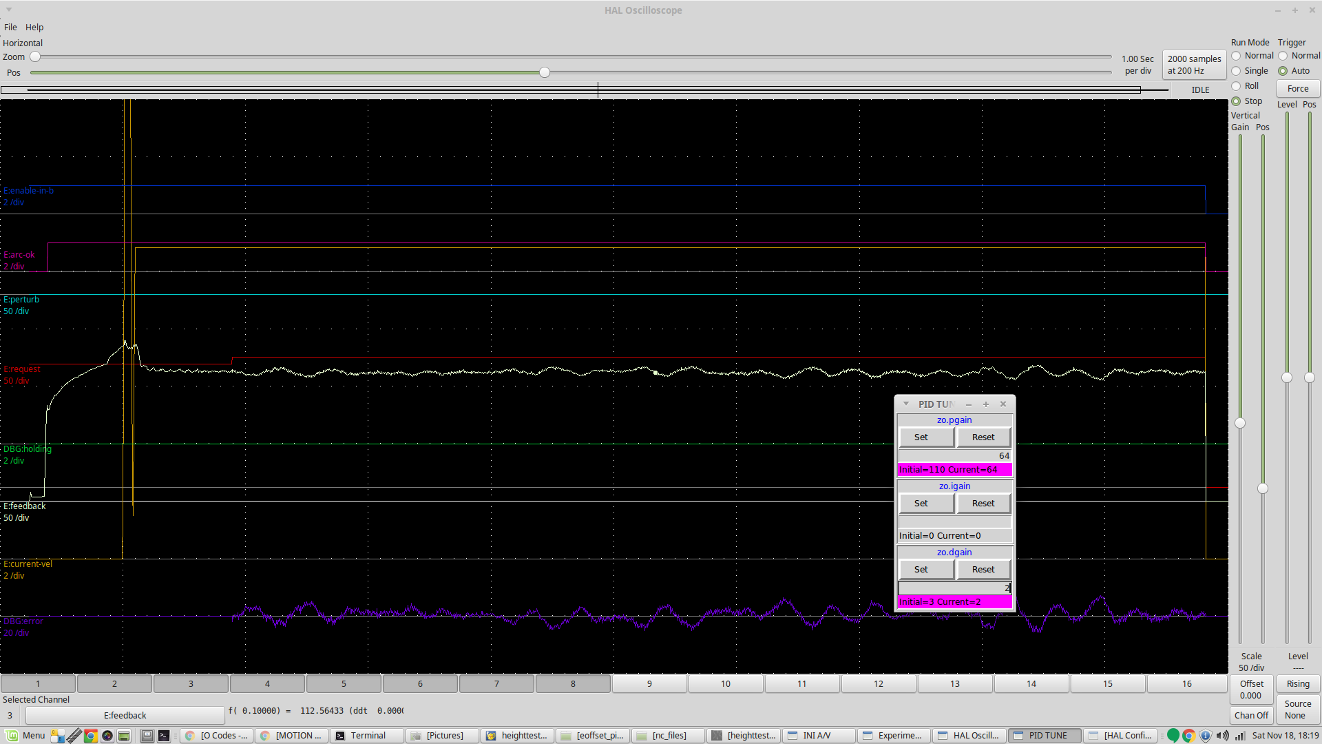
You can see that the voltage is sampled 1.5 seconds after ArcOK and it wobbles along OK. I just have to learn more about tuning the pid loop. If anybody has a procedure they can share or a link to a tutorial, it would be great if you could chip in.
Anyway, its been a long road to get here, hopefully it will come together quickly from here.
This is cutting 8mm mild steel.
You can see that the voltage is sampled 1.5 seconds after ArcOK and it wobbles along OK. I just have to learn more about tuning the pid loop. If anybody has a procedure they can share or a link to a tutorial, it would be great if you could chip in.
Anyway, its been a long road to get here, hopefully it will come together quickly from here.
The following user(s) said Thank You: tommylight
Please Log in or Create an account to join the conversation.
- tommylight
-

- Away
- Moderator
-

Less
More
- Posts: 21738
- Thank you received: 7428
19 Nov 2017 03:29 #101991
by tommylight
Replied by tommylight on topic Rods "Spaceship" Scratch built Plasma Cutter build
I do not think my experience tunning servo motors would help in this case.
You have done a great job.
Regards,
Tom
You have done a great job.
Regards,
Tom
Please Log in or Create an account to join the conversation.
- rodw
-
Topic Author
- Away
- Platinum Member
-
Less
More
- Posts: 12032
- Thank you received: 4104
19 Nov 2017 09:44 #101997
by rodw
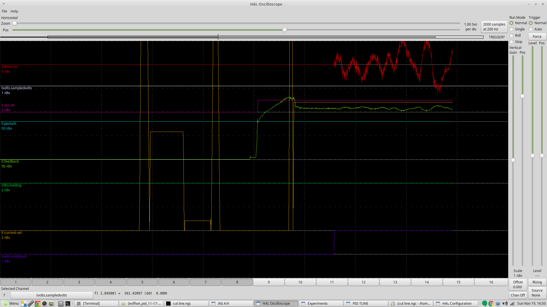
I did some test cuts yesterday to try and determine the change in volts per mm of torch height and ran the simulator again with about 5 volts per mm instead of 10 volts per mm. Whilst it changed the tuning, the oscillation is still there.
Sorry, I forgot to include the PID settings in the screen dump. This is with p = 15, i = 0.0128, d = 0.6
In the SIM, small amounts of I moves the volts up and down to centre it on the setpoint.
With all of the settings I've played with nothing seems to get rid of the oscillation and it seems pretty constant regardless of the PID settings.
I've been doing some research about PID tuning. I'm beginning to think that the eoffset scale setting Dewey has told us to use might be too high in the real world even though he had a mathematical reason to set it to where it is.
If you read the external offsets documentation, it says that the scale parameter is similar to the scaling for an encoder.. I think my next experiment will be to halve the scale and leave the PID untouched. What do you think?
Replied by rodw on topic Rods "Spaceship" Scratch built Plasma Cutter build
Tommy, thanks for the encouragement. When I crack this PID, it will be a really great job! Perhaps you can help though. What causes oscillation and how do you eliminate it in a PID control? There is still a motor involved so some of the response parameters will be similar.I do not think my experience tunning servo motors would help in this case.
You have done a great job.
Regards,
Tom
I did some test cuts yesterday to try and determine the change in volts per mm of torch height and ran the simulator again with about 5 volts per mm instead of 10 volts per mm. Whilst it changed the tuning, the oscillation is still there.
Sorry, I forgot to include the PID settings in the screen dump. This is with p = 15, i = 0.0128, d = 0.6
In the SIM, small amounts of I moves the volts up and down to centre it on the setpoint.
With all of the settings I've played with nothing seems to get rid of the oscillation and it seems pretty constant regardless of the PID settings.
I've been doing some research about PID tuning. I'm beginning to think that the eoffset scale setting Dewey has told us to use might be too high in the real world even though he had a mathematical reason to set it to where it is.
If you read the external offsets documentation, it says that the scale parameter is similar to the scaling for an encoder.. I think my next experiment will be to halve the scale and leave the PID untouched. What do you think?
Please Log in or Create an account to join the conversation.
- Mike_Eitel
-

- Offline
- Platinum Member
-
Less
More
- Posts: 1052
- Thank you received: 183
19 Nov 2017 10:15 #101998
by Mike_Eitel
Replied by Mike_Eitel on topic Rods "Spaceship" Scratch built Plasma Cutter build
This writing describs how to tune PID for mass-effect-compensation in the old way.
Unterstand P as a pure 2 point regulator whitch is damped by D.
And I as error "corector"...
robotics.stackexchange.com/questions/167...for-tuning-pid-loops
Unterstand P as a pure 2 point regulator whitch is damped by D.
And I as error "corector"...
robotics.stackexchange.com/questions/167...for-tuning-pid-loops
Please Log in or Create an account to join the conversation.
- rodw
-
Topic Author
- Away
- Platinum Member
-
Less
More
- Posts: 12032
- Thank you received: 4104
19 Nov 2017 11:14 #101999
by rodw
Mike, thanks, I've pored through that link and the very interesting PDF file linked there which I printed out.. The intent of the External offset developer (Dewey Garrett) was to be able to replicate your hardware (eg. Velocity and Acceleration) in a software simulator and do most of your tuning there. This seems to be quite common practice in the world of PID. The unknown is the torch parameters. Dewey says I is not useful as this PID functions as an inner loop within LinuxCNC. I have found in the SIM that small amounts of I align the response with the setpoint. I was hoping that changing some of the torch simulation parameters to be more in line with my plasma cutter but it was not to be.
By and large the SIMULATOR is very helpful as straight off the bat, it gives you a working (but oscillating) system. I've had a few iterations (as has the eoffset branch) but when I look back , I've got a similarly oscillating system with a large range of P values from about 10 through to 120 and the outcome has been the same with the oscillation amplitude being similar. Thats what is making me think that possibly the eoffset scale is too strong and its resulting in overshoot. This has been suggested in some of my readings.
Replied by rodw on topic Rods "Spaceship" Scratch built Plasma Cutter build
This writing describs how to tune PID for mass-effect-compensation in the old way.
Unterstand P as a pure 2 point regulator whitch is damped by D.
And I as error "corector"...
robotics.stackexchange.com/questions/167...for-tuning-pid-loops
Mike, thanks, I've pored through that link and the very interesting PDF file linked there which I printed out.. The intent of the External offset developer (Dewey Garrett) was to be able to replicate your hardware (eg. Velocity and Acceleration) in a software simulator and do most of your tuning there. This seems to be quite common practice in the world of PID. The unknown is the torch parameters. Dewey says I is not useful as this PID functions as an inner loop within LinuxCNC. I have found in the SIM that small amounts of I align the response with the setpoint. I was hoping that changing some of the torch simulation parameters to be more in line with my plasma cutter but it was not to be.
By and large the SIMULATOR is very helpful as straight off the bat, it gives you a working (but oscillating) system. I've had a few iterations (as has the eoffset branch) but when I look back , I've got a similarly oscillating system with a large range of P values from about 10 through to 120 and the outcome has been the same with the oscillation amplitude being similar. Thats what is making me think that possibly the eoffset scale is too strong and its resulting in overshoot. This has been suggested in some of my readings.
Please Log in or Create an account to join the conversation.
- robertspark
- Offline
- Platinum Member
-
Less
More
- Posts: 915
- Thank you received: 216
19 Nov 2017 11:21 #102000
by robertspark
Replied by robertspark on topic Rods "Spaceship" Scratch built Plasma Cutter build
Why are you thinking about it in terms of volts per mm?
Why not think of it in terms of volts per step?.... That way the settings can be adapted universally..... Plus you are only interested in the amount of "error", and you correct for the error my moving a number of steps
Next.... PID tuning requires the.process to be repeatable.... Do you see the process as being repeatable?.... What conditions make the process repeatable?
For the process to be repeatable everything process wise needs to be the same then you can vary the setpoint and the corrective action device (z-axis) can move to the corrected location....
I think you are going to struggle tuning PID now without factoring in feedrate... The feedrate will affect the speed of the corrective action you require..... Whilst the error may be the same the rate of response will be different because the cut speed and therefore voltage may be varying quicker or slower.
Suggestion.... Forget about PID tuning for a moment.... Do some test cuts
Set up a gcode file moving in one direction say from x0 to X?, Using the book (or your optimum) feedrate
X? Is to be determined by giving your machine say a good 5-10 seconds of cut time, because your voltage takes ~1.5 sec to stabilise.
What you are looking to do is to find out the voltage variance per say 10 / 20/ 50 / 100 z axis steps.
So you want the cuts side by side offset so that dross does not affect the adjacent cut or voltage reading (hence you want say 10mm clearance from the of of the torch or torch cap)
You also want to zero your torch at the start of the cut, and at the end of the cut you want to probe the height of the plate (this requires no top side dross or divot at the cut)
Don't voltage track (sample and hold during the cut)... You want the z axis locked / non moving....
You want to obtain the plots from points x0 to X? And you want to know that at the start of the cut what the height of the torch is and you want to find out what the height of the torch was at the end of the cut.
Let's say your recommended cut height is 3mm, and the book voltage at this height for 8mm plate is 135v, you want to do say 6 test cuts even 7 all using the same gcode file (because the torch consumables may warm up during your first cut which may change the parameters and logs obtained later)
First cut at 3mm
Next cut at 3mm+10 steps
Next cut at 3mm +20 steps
Next cut at 3mm
Next cut at 3mm -10 steps
Next cut at 3mm -20 steps
Next cut at 3mm
(The cut height is your touch off height... You will need to run a g31 at the end of the cut to establish what the cut height is at the end of the cut as the bed may be slightly rising or falling or have dross on it etc plus the metal may have changed shape)
Now the +10 and +20 steps are just an approximation as you want something as a meaningful distance that will show you a meaningful voltage reading between all of the cuts ..... You don't want to do a 3mm cut... Then one at 4mm and one at 5mm as then you will need to do one at 2mm and 1mm going the other way and your voltage change may be very large and you may also crash with the plate or dross at 1mm or the pierce pool when dropping from pierce to cut height
Choose your units such they mean something to you and are the Lilley distances that your torch / z axis may need to be correcting.
Armed with this data you now know the error (voltage variance) per unit (step) and you can approximate this into 0.1mm... 0.5mm or 1mm
Next we can look at the PID and adding a responsiveness factor.... Which is to be derived from your feedrate (actual not set) and also from your z axis acceleration to calculate your maximum z axis THC velocity using centripetal acceleration as the torch may need to one moment be going down and then the next going up (with a 1khz sampling rate we want this as which and smooth as possible) and the distance moved to be very short between samples but relative to the feedrate because we know that the voltage will not vary greatly if the feedrate is low (unless we hit a kerf / gap... Which will be ignored)
Please Log in or Create an account to join the conversation.
- robertspark
- Offline
- Platinum Member
-
Less
More
- Posts: 915
- Thank you received: 216
19 Nov 2017 11:45 #102002
by robertspark
Replied by robertspark on topic Rods "Spaceship" Scratch built Plasma Cutter build
On hindsight (of having a think + shower following typing tourettes)... Ignore the centrpetal acceleration bit it would not be correct , one with 2 or more blended axis motion)... Standard linear acceleration would be fine plus correct.
It may also be useful to perform the same test cuts on 6mm and or 3mm plate too at the correct book feedrate so that you can establish the voltage variances per unit are hopefully the same.... Or close...
With hypertherm the cut heights are the same for all the same material but different thicknesses to the 3mm +10 +20 or whatever you use should stand true
The voltage will be lower though... But you are not really interested in what the voltage actually is... You are trying to find the voltage variance per unit accurately from the book cut height to these higher and lower cut heights
Given the feedrate is higher you will need to have a longer cut run for the thinner materials too so you can factor in the 1.5 sec of voltage stabilisation at the start of the cut
Please Log in or Create an account to join the conversation.
- robertspark
- Offline
- Platinum Member
-
Less
More
- Posts: 915
- Thank you received: 216
19 Nov 2017 11:49 #102003
by robertspark
Replied by robertspark on topic Rods "Spaceship" Scratch built Plasma Cutter build
When calculating your distance of run you need to think about the cut sequence and what it will give you voltage wise....
M3 .... Pause for pierce.... Accelerate to cut velocity (exclude 1.5 sec for voltage stabilisation).... 5 sec at cut velocity, decelerate to zero, M5 torch off.... Exclude end of cut as torch slowing down voltage may be rising as kerf gets wider plus end of cut divot
Focus on the bit in the middle only
Please Log in or Create an account to join the conversation.
Time to create page: 0.226 seconds