Rods "Spaceship" Scratch built Plasma Cutter build
- rodw
-
 Topic Author
- Offline
- Platinum Member
-

Less
More
- Posts: 11691
- Thank you received: 3942
05 Aug 2017 10:55 #97024
by rodw
Replied by rodw on topic Rods "Spaceship" Scratch built Plasma Cutter build
Thanks guys. For interest, here is a excerpt from the halsampler output. Headings added for clarity. Since this capture, I've added an extra value for the raw voltage read by the THCAD card. In my case it should be between 0-20 volts as I've scaled it with an external resistor.
This data streams in 1000 times a second
Here is an excerpt from my hal files. This is probably not complete.
sampler seems to be fussy about syntax and I found it was hard to set from a signals so I had to add it to the line that created the signal so it received its value directly from a pin. This meant the code got scattered around a bit more than I wanted. With this set up in your hal, you just need to run the halsampler command from the command line. Check the docs for syntax.
So I'm all set for another round of tests tomorow. I've been lent a high quality Agilent multimeter as mineseems to be very slow reading values and updating the display.
A couple of pics.
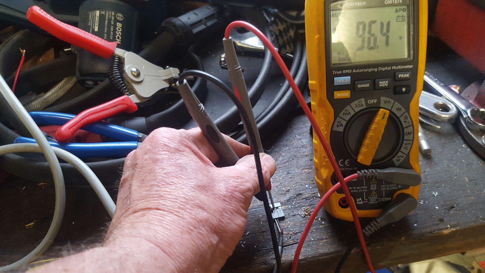
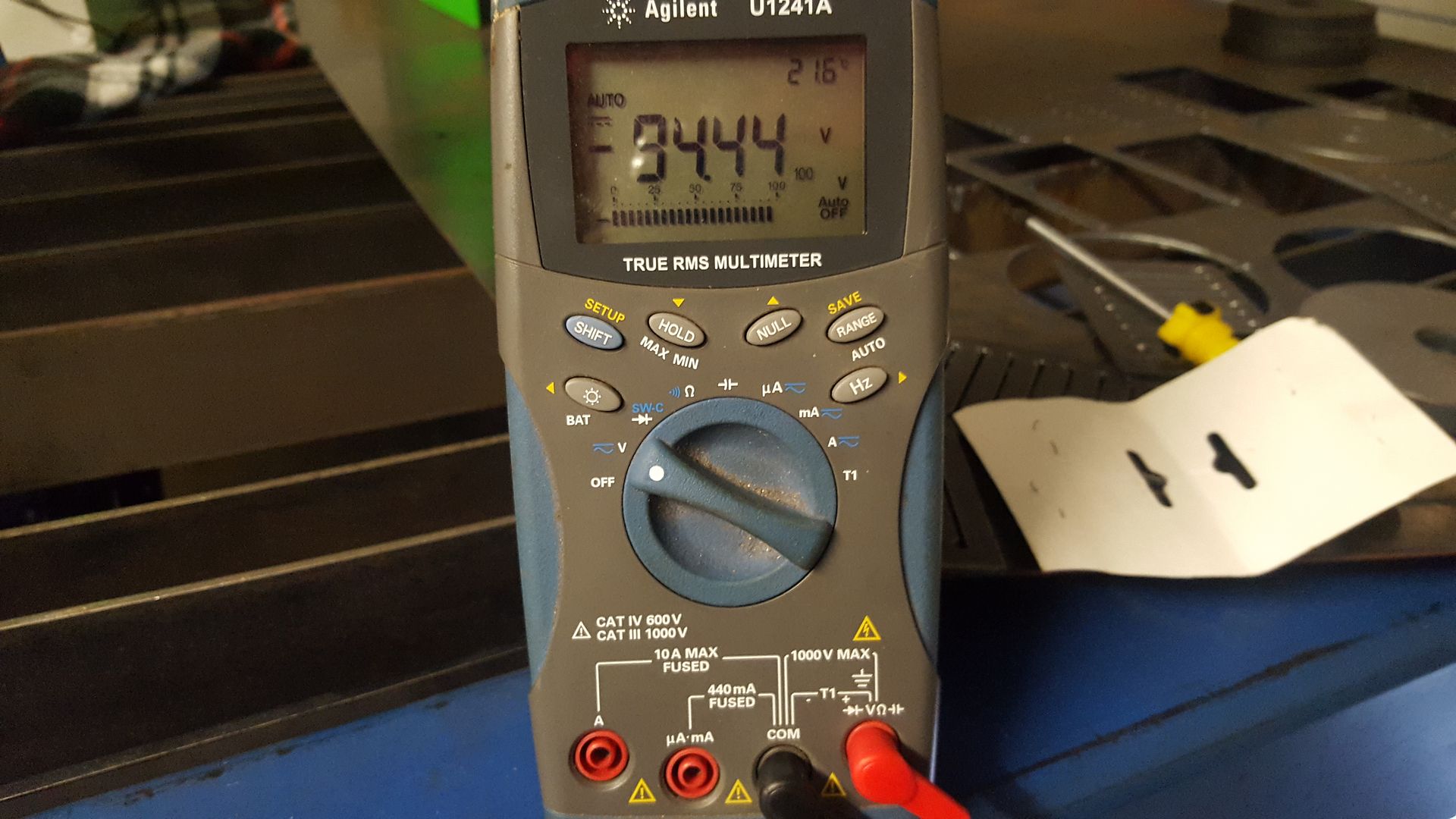
Wires to multimeter for raw arc voltage
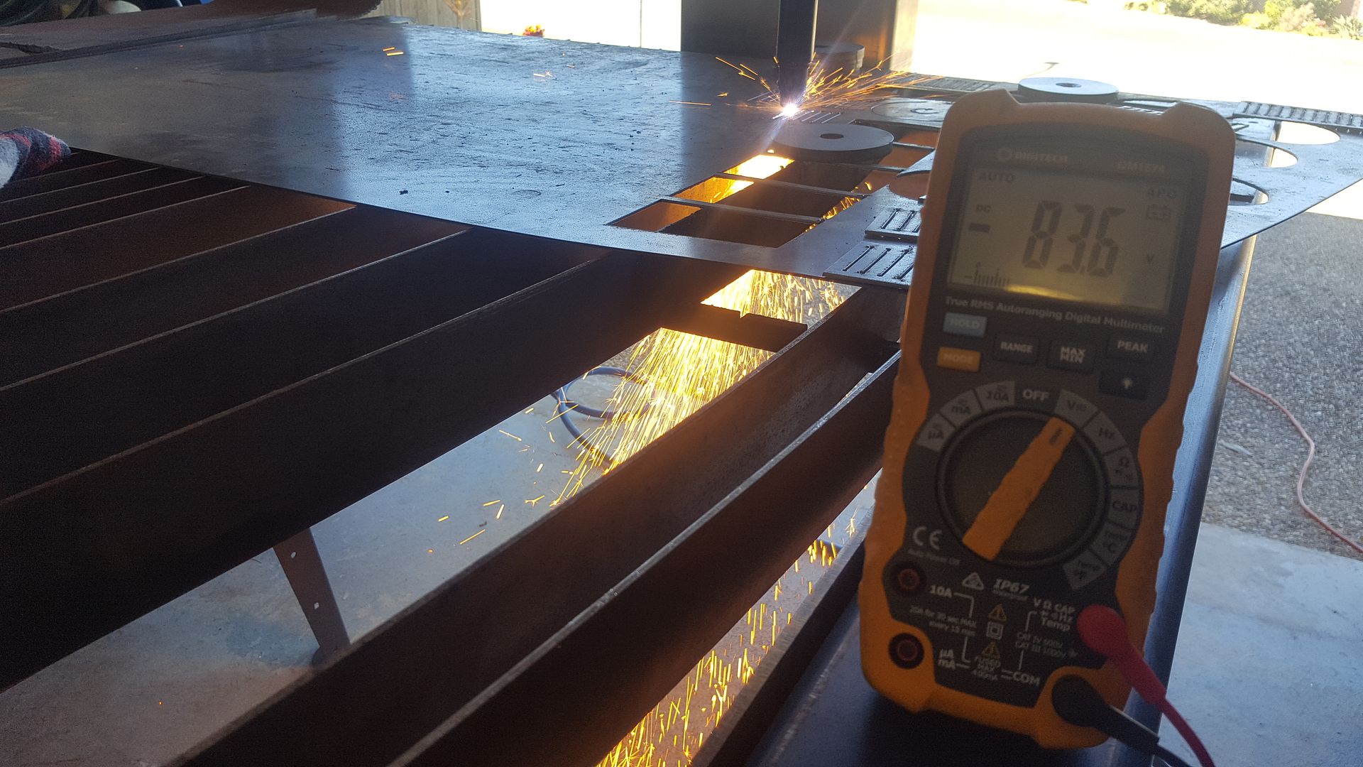
And raw arc voltage
X coord    Y coord     Z coord   Volts     THCAD freq
263.000000 380.000000 -55.234143 81.969943 10266.940452
263.000000 380.000000 -55.237488 84.435688 10460.251046
263.000000 380.000000 -55.240757 83.754051 10406.811731
263.000000 380.000000 -55.243952 82.781669 10330.578512
263.000000 380.000000 -55.247072 83.741494 10405.827263
263.000000 380.000000 -55.250117 83.004798 10348.071496
263.000000 380.000000 -55.253087 82.104535 10277.492292
263.000000 380.000000 -55.255982 81.969943 10266.940452
263.000000 380.000000 -55.258802 82.509978 10309.278351
263.000000 380.000000 -55.261547 82.917936 10341.261634
263.000000 380.000000 -55.264217 81.567819 10235.414534
263.000000 380.000000 -55.266812 81.835627 10256.410256
263.000000 380.000000 -55.269332 82.756924 10328.638498
This data streams in 1000 times a second
Here is an excerpt from my hal files. This is probably not complete.
loadrt sampler depth=10000 cfg=ffffff
addf sampler.0                servo-thread
# x,y,z,volts, THCAD volts, velocity
net sample0 sampler.0.pin.0 <= axis.x.pos-cmd
net sample1 sampler.0.pin.1 <= axis.y.pos-cmd
net z-position   <= sampler.0.pin.2 <= axis.z.pos-cmd
net curvolt <= sampler.0.pin.3 <= thcad10.torch-volts
net THCAD-volts-in  <= sampler.0.pin.4 <= thcad10.thcad-volts
net THCAD-velocity-in  <= sampler.0.pin.5 <= hm2_7i76e.0.encoder.00.velocity
sampler seems to be fussy about syntax and I found it was hard to set from a signals so I had to add it to the line that created the signal so it received its value directly from a pin. This meant the code got scattered around a bit more than I wanted. With this set up in your hal, you just need to run the halsampler command from the command line. Check the docs for syntax.
So I'm all set for another round of tests tomorow. I've been lent a high quality Agilent multimeter as mineseems to be very slow reading values and updating the display.
A couple of pics.
Wires to multimeter for raw arc voltage
And raw arc voltage
Please Log in or Create an account to join the conversation.
- racedirector
- Offline
- Elite Member
-

Less
More
- Posts: 231
- Thank you received: 42
06 Aug 2017 00:24 #97054
by racedirector
Replied by racedirector on topic Rods "Spaceship" Scratch built Plasma Cutter build
Rod
Very impressed with what you are doing, I have been thinking of building a plasma cutter for a while. I watch your thread silently to "borrow" all your knowledge
Very impressed with what you are doing, I have been thinking of building a plasma cutter for a while. I watch your thread silently to "borrow" all your knowledge
The following user(s) said Thank You: rodw
Please Log in or Create an account to join the conversation.
- islander261
- Offline
- Platinum Member
-

Less
More
- Posts: 757
- Thank you received: 216
06 Aug 2017 03:31 #97057
by islander261
Replied by islander261 on topic Rods "Spaceship" Scratch built Plasma Cutter build
Rod
We are here! You are in uncharted territory for most of us with your chinacom power supply. I will say that the arc voltage measurement was one of the first things I got worked out with my setup... long before I tried any motion. I actually did a lot of measuring with both a good multi-meter and an oscilloscope of the raw arc voltage before I made my voltage divider / filter circuit. I then tested the voltage divider / filter circuit observing the output with the multi-meter and oscilloscope long before connecting to to my THCad card. The end result was that my displayed arc voltage was spot on the first time I tried to observe it with my LinuxCNC system.
Keep up the good work.
John
The following user(s) said Thank You: rodw
Please Log in or Create an account to join the conversation.
- rodw
-
 Topic Author
- Offline
- Platinum Member
-

Less
More
- Posts: 11691
- Thank you received: 3942
06 Aug 2017 04:46 #97060
by rodw
Thanks mate. This has been a much longer journey than I ever anticipated.
John, Thanks for the encouragement. Its frustrating to find problems in purchased equipment. I can make enough problems myself without others adding to them. I did not have the luxury of a working table to experiment with and I don't have any test gear.
In reality, it does not matter 2 hoots what the voltage is, just as long as you have a target to work to either as a calibration to enter into the machine or a sampled frequency from the THCAD. I had always assumed you would use the frequency as the pid control input. But it would be nice to display an accurate voltage reading for the operator.
I think the one solution would be to parallel 2 x 48 volt power supplies together to give me 96 volts and calibrate the divider using that. Meanwell show a circuit for joining power supplies. You just need to add a couple of diodes. I do have a couple of 48V power supplies here but one is a 7 amp Meanwell and the other is a 10amp Chinese one. Meanwell do say the amperage should be the same.
If I can find the same connector as is used on the CNC board, I could just wire it up insitu with the plasma turned off and everything else disconnected form the CNC board.
Any thoughts on that? Am I likely to blow them up? Or should I buy a couple of small ones to be safe?
Replied by rodw on topic Rods "Spaceship" Scratch built Plasma Cutter build
Rod
Very impressed with what you are doing, I have been thinking of building a plasma cutter for a while. I watch your thread silently to "borrow" all your knowledge
Thanks mate. This has been a much longer journey than I ever anticipated.
Rod
We are here! You are in uncharted territory for most of us with your chinacom power supply. I will say that the arc voltage measurement was one of the first things I got worked out with my setup... long before I tried any motion. I actually did a lot of measuring with both a good multi-meter and an oscilloscope of the raw arc voltage before I made my voltage divider / filter circuit. I then tested the voltage divider / filter circuit observing the output with the multi-meter and oscilloscope long before connecting to to my THCad card. The end result was that my displayed arc voltage was spot on the first time I tried to observe it with my LinuxCNC system.
Keep up the good work.
John
John, Thanks for the encouragement. Its frustrating to find problems in purchased equipment. I can make enough problems myself without others adding to them. I did not have the luxury of a working table to experiment with and I don't have any test gear.
In reality, it does not matter 2 hoots what the voltage is, just as long as you have a target to work to either as a calibration to enter into the machine or a sampled frequency from the THCAD. I had always assumed you would use the frequency as the pid control input. But it would be nice to display an accurate voltage reading for the operator.
I think the one solution would be to parallel 2 x 48 volt power supplies together to give me 96 volts and calibrate the divider using that. Meanwell show a circuit for joining power supplies. You just need to add a couple of diodes. I do have a couple of 48V power supplies here but one is a 7 amp Meanwell and the other is a 10amp Chinese one. Meanwell do say the amperage should be the same.
If I can find the same connector as is used on the CNC board, I could just wire it up insitu with the plasma turned off and everything else disconnected form the CNC board.
Any thoughts on that? Am I likely to blow them up? Or should I buy a couple of small ones to be safe?
Please Log in or Create an account to join the conversation.
- Mike_Eitel
-

- Offline
- Platinum Member
-

Less
More
- Posts: 1052
- Thank you received: 183
06 Aug 2017 09:25 #97062
by Mike_Eitel
Replied by Mike_Eitel on topic Rods "Spaceship" Scratch built Plasma Cutter build
M5C
I have no clue of THC but I'm electronic engineer.
I don't know if my way is dangerous for your electronic, but doubt it.
Take a known DC voltage and connect it via resistor,1k-10k, to your torch.
(Measure behind resistor will show if there is current flowing, allowing to destroy anything in your electronics...)
Than measure the voltage going to your message input. Simple compare those two voltages gives you the divisor...
What I expect is that a plasma generates a lot of radio frequency, and I would not trust a normal meter to show the correct DC part anyhow. But there are more experienced guys on this forum than me..
P.S.
Using lcnc since 99... Super soft!
Reading this forum most days, never commenting.
Mike
Please Log in or Create an account to join the conversation.
- rodw
-
 Topic Author
- Offline
- Platinum Member
-

Less
More
- Posts: 11691
- Thank you received: 3942
06 Aug 2017 10:44 #97063
by rodw
Replied by rodw on topic Rods "Spaceship" Scratch built Plasma Cutter build
Well I did it and did not blow anything up!
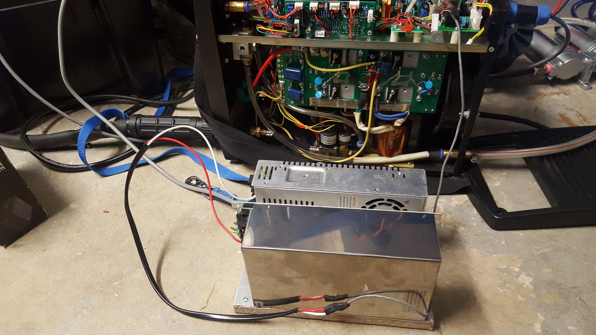
I screwed a couple of 48 volt power supplies I've accumulated through this project onto a piece of chipboard and connected them in series. Cool!
This is just perfect and somewhere in the cutting range.
So I disconnected all of the wires form the CNC board after tagging a wire with some tape (remind me tape = top)
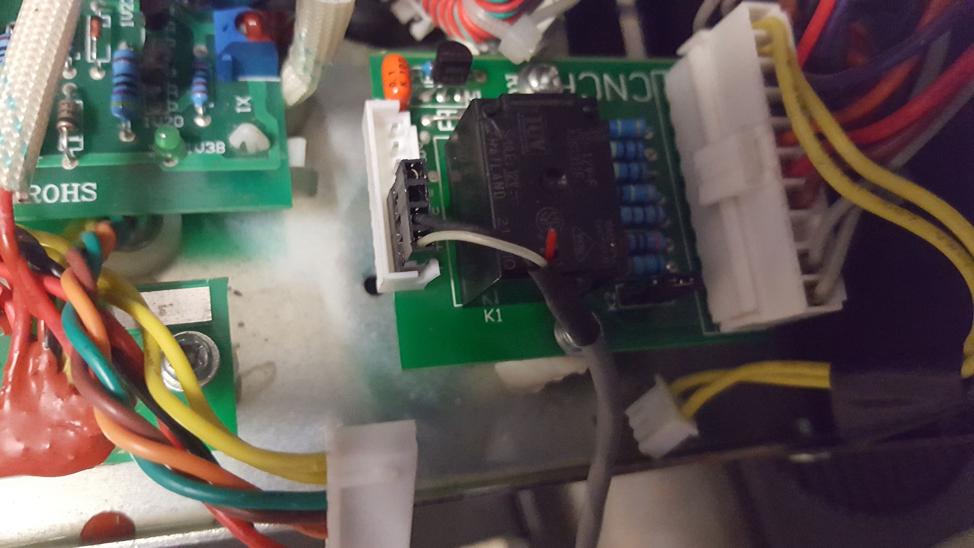
And plugged this into where the torch voltage enters the CNC board
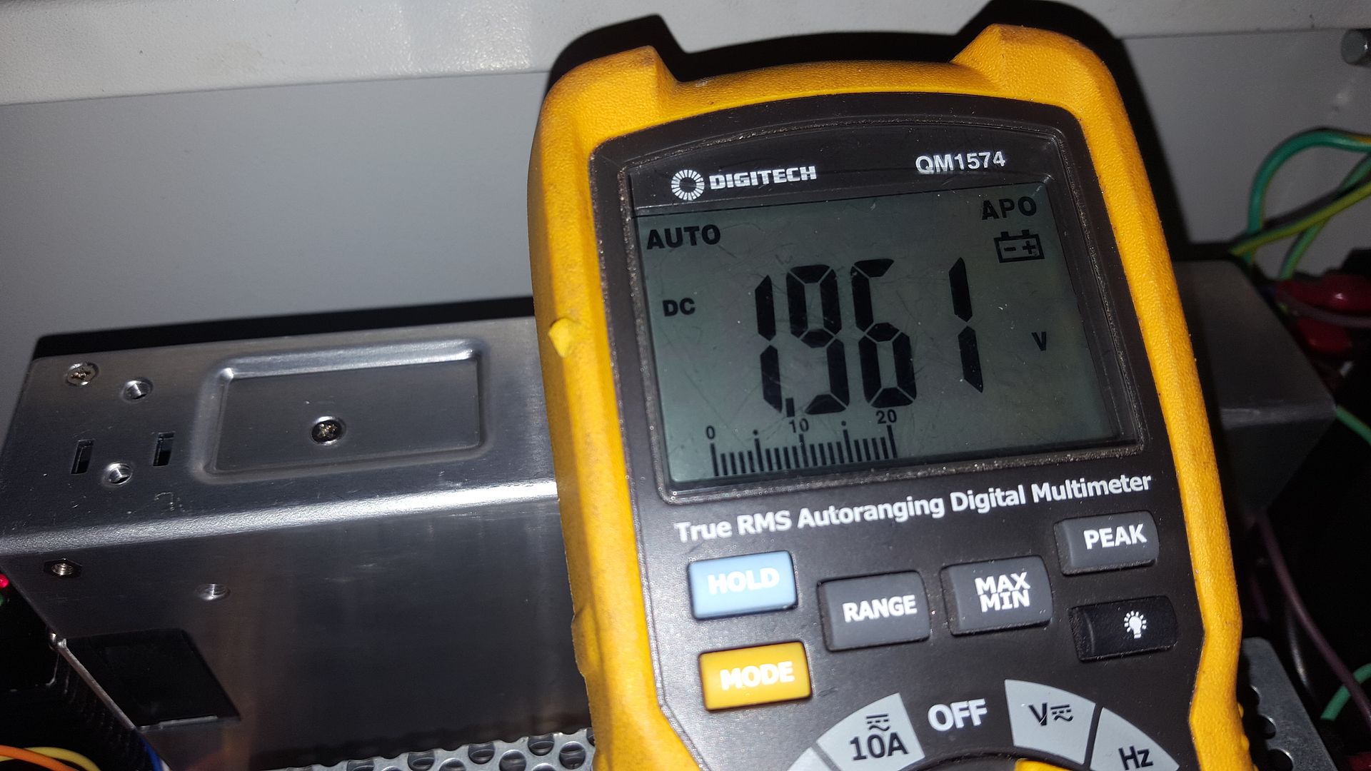
And fired up the power supply and LinuxCNC. THere was a 1.95 volt drop across the spark arresting resistors on the raw voltage connectors.
and then checked the voltage at the control box.
Now I had something to work with! The so called 16:1 divider showed up as 48:1. So I plugged this ratio into my hal file and felt I was getting somewhere. Looking at LinuxCNC, something did not look wight, I was out by a factor of 2. Then I remembered I had a scaling resistor for the THCAD in the cable connector so I checked the voltage at the other (plasma) end of the cable. Yup it was double the voltage at the cabinet. So now I reworked the divider ratios. The were way out in comparison with the Everlast plasma manual:
Everlast manual 50:1 divider. Actual measured 76.0:1
Everlast manual 16:1 divider. Actual measured 24.5:1
So I plugged these results into my hal file and got perfect calculated voltage!
I had a look at a random sample of voltage. The THCAD reported voltage was +- 0.7% of the power supply voltage. I'm a happy man!
I'm very annoyed about the hours this weekend I'll never get back becasue of totally wrong documentation.
I might look at the scaling resistor value. Previously for a 16:1 divider the full scale is 320 volts.Now that torch voltage is only 65% of full scale. I'll wait until I see some cutting data before I decide what to do. If I take the scaling resistor out altogether, the full scale will be 245 volts which may well be enough!
Anyway, now I've got accurate torch voltage reading into LinuxCNC, I'll be able to move ahead with cut heights on different materials and then finally Torch height control!
Please Log in or Create an account to join the conversation.
- rodw
-
 Topic Author
- Offline
- Platinum Member
-

Less
More
- Posts: 11691
- Thank you received: 3942
06 Aug 2017 10:51 #97064
by rodw
Thanks for your advice. That basically is what I ended up doing.
I'm glad I coaxed you out from under your log
Replied by rodw on topic Rods "Spaceship" Scratch built Plasma Cutter build
M5C
I have no clue of THC but I'm electronic engineer.
I don't know if my way is dangerous for your electronic, but doubt it.
Take a known DC voltage and connect it via resistor,1k-10k, to your torch.
(Measure behind resistor will show if there is current flowing, allowing to destroy anything in your electronics...)
Than measure the voltage going to your message input. Simple compare those two voltages gives you the divisor...
What I expect is that a plasma generates a lot of radio frequency, and I would not trust a normal meter to show the correct DC part anyhow. But there are more experienced guys on this forum than me..
P.S.
Using lcnc since 99... Super soft!
Reading this forum most days, never commenting.
Mike
Thanks for your advice. That basically is what I ended up doing.
I'm glad I coaxed you out from under your log
Please Log in or Create an account to join the conversation.
- Mike_Eitel
-

- Offline
- Platinum Member
-

Less
More
- Posts: 1052
- Thank you received: 183
06 Aug 2017 10:51 #97065
by Mike_Eitel

I'm happy to help. Love to read your journey.
Mike
Replied by Mike_Eitel on topic Rods "Spaceship" Scratch built Plasma Cutter build
I'm happy to help. Love to read your journey.
Mike
Please Log in or Create an account to join the conversation.
- rodw
-
 Topic Author
- Offline
- Platinum Member
-

Less
More
- Posts: 11691
- Thank you received: 3942
09 Aug 2017 05:13 #97229
by rodw
Replied by rodw on topic Rods "Spaceship" Scratch built Plasma Cutter build
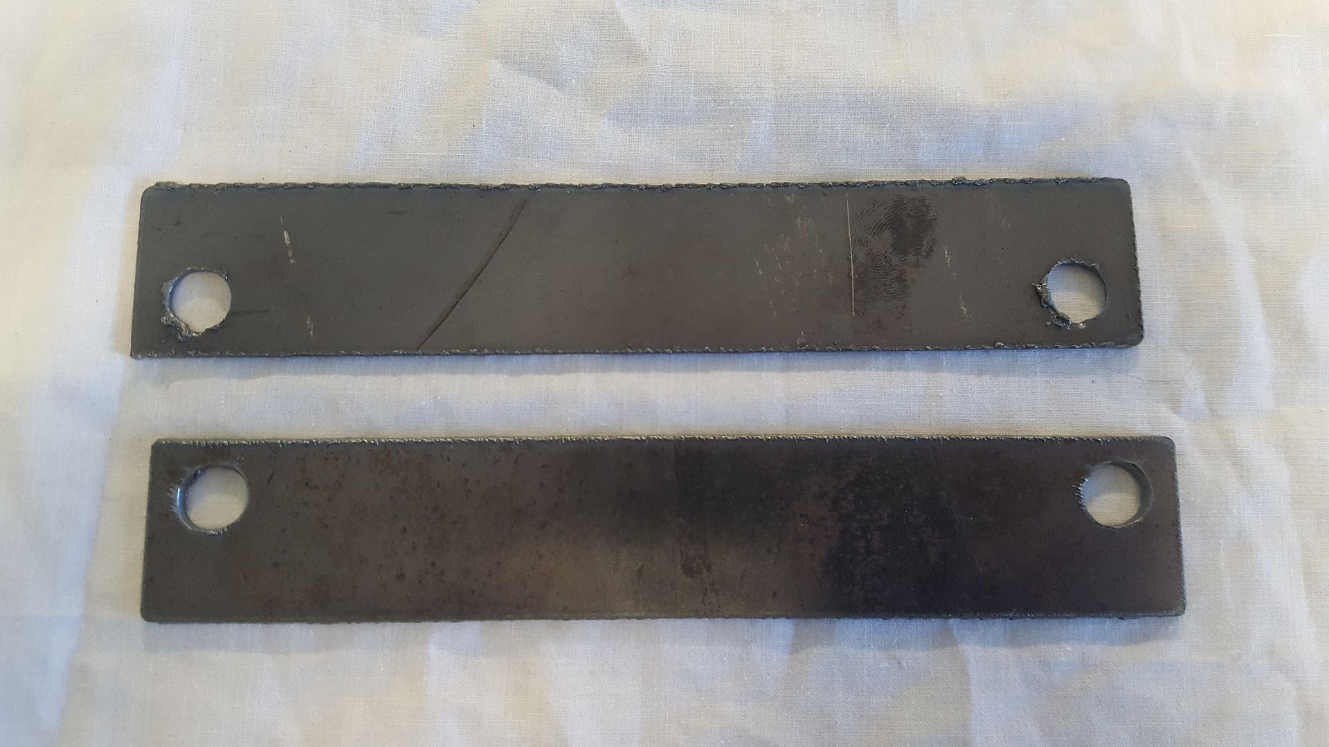
Well, here is the first commercial parts (front and back shown before cleanup). Both were nested and cut as one job.
We've paid up to $9.50 each for these parts from laser cutters and somebody ordered the wrong part so I thought it was agood opportunity to try something for real.
Nothing special, the holes are not round but there is a couple of nutserts to go in them and they will be fine as I had to run a drill through them before the nutserts would fit.
The torch was running at a stable 84 volts for the duration of the cuts. Nice!
I still have to sort out the post processor in sheetcam. The one I borrowed needs some work as the torch was lifting after dropping to cut height so I had to hand edit the Gcode. For some strange reason, the leadins on both parts were different. The first one did not separate cleanly at the start point but the second one just fell out nicely.
I was a bit worried for a while because after all the time mucking with the plasma internals, I could not get anything to cut so I thought I'd broken it. I finally realised that I'd knocked the earth lead out of the machine and being a pilot arc torch, it would still fire but was only good for dotted lines... Don't ask me how much time that wasted...
Now they want me to cut another set of the whole job which is an infill plate if you don't install a winch in a bullbar.
I need to play with torch height now as the cuts are a bit angular top to bottom.
Please Log in or Create an account to join the conversation.
- rodw
-
 Topic Author
- Offline
- Platinum Member
-

Less
More
- Posts: 11691
- Thank you received: 3942
16 Aug 2017 14:21 #97574
by rodw
Replied by rodw on topic Rods "Spaceship" Scratch built Plasma Cutter build
Well I branched out on this thread
forum.linuxcnc.org/10-advanced-configura...plasma-machine#97573
and I got BigJohnT's attention on the IRC and he got Dewey to help
So now I have THC control happening (if you don't mind crashing 3 seconds after starting a cut!)
So I need some tuning from here.
The video shows all of the external offset signals. first inputs a,b,c are enabled (after the THC starting delay), then enable-out goes true and the one I wanted to see was zo.active come on to tell me that offsets were enabled!
Please Log in or Create an account to join the conversation.
Time to create page: 0.625 seconds

