Rods "Spaceship" Scratch built Plasma Cutter build
- rodw
-
 Topic Author
- Offline
- Platinum Member
-

Less
More
- Posts: 12007
- Thank you received: 4089
22 Dec 2016 13:04 #84550
by rodw
Rods "Spaceship" Scratch built Plasma Cutter build was created by rodw
You can blame my wife for the title. She was lamenting over how much time I was spending in my shed building what to her might as well be a spaceship as she could not comprehend what was going on.
I've been meaning to start a build thread for quite a while but yesterday something happened that I thought made a a good place to start.
Allow you to present to you some dome nuts valued at AUD $174.24
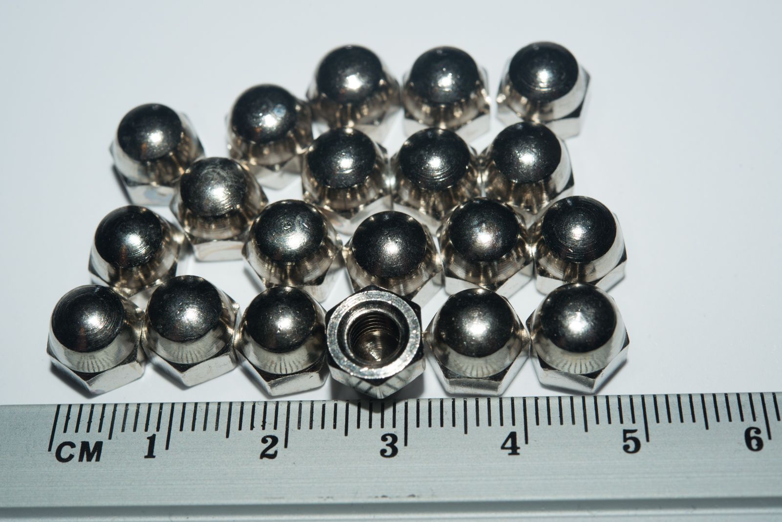
Yep, that's what my bolt shop charged me for these 20 solid brass nickel plated dome nuts yesterday. After a terse email or 2 the price settled to a more reasonable $8.67 by the end of today. The embarrassing thing was that I didn't use any of them becasue the M4 stainless steel ones I bought a week or so ago was the right size (and half the price)!
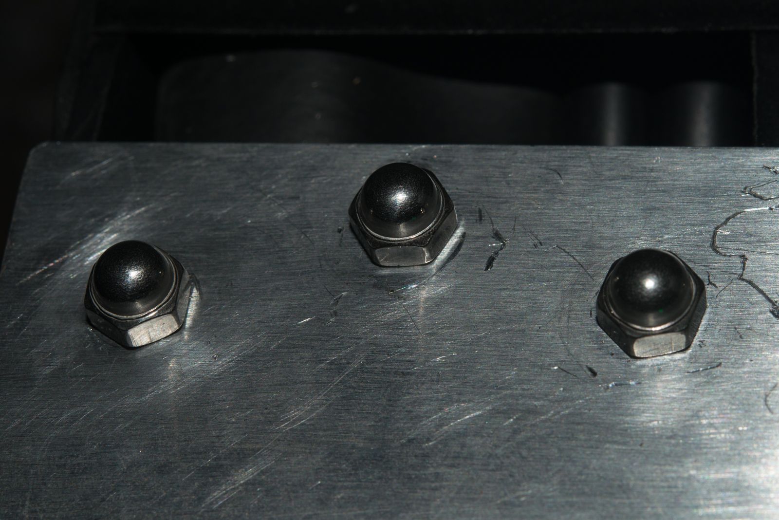
I really only needed 6 to secure the drag chain at each end
and 3 of them are pretty much out of sight. I'm sure you will agree that these add a certain amount of profesisonalism to my plasma cutter.
Anyway, while I had the camera out, I thought I better take a couple more pics.
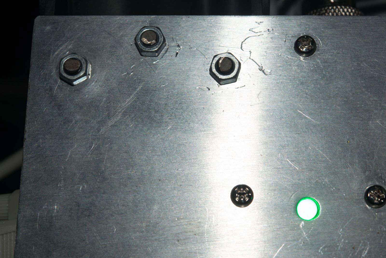
This one shows where these bolts belong and you can see that I've got a little circuit board tucked underneath. This is simply a DB9 connector soldered to a piece of vero board. that is broken out into 7 x 3 wire terminal blocks for each of the limit switches (1 wire for the signal and the other 2 for 24V power.. The remaining 2 wires in the 5m DB9 cable are used for 24 volt power. I made a bit of a stuffup and ordered a bunch of NPN proximity switches only to find the Mesa boards play much more nicely with PNP sensors. This did not prove a drama and it was easy to add a few pullup resistors (2.2K x 1 W) to the circuit board. I also added a LED to the 24 volt power so I had a visual trouble shooting aid for when things go wrong. The LED current limiting resistor has been set for 10 mA.You can see it in one of the pics above.
The black grommets just fill in some oversized holes to let me mount the gear rack on the fornt face using M6 socket head screws.
I've been meaning to start a build thread for quite a while but yesterday something happened that I thought made a a good place to start.
Allow you to present to you some dome nuts valued at AUD $174.24
Yep, that's what my bolt shop charged me for these 20 solid brass nickel plated dome nuts yesterday. After a terse email or 2 the price settled to a more reasonable $8.67 by the end of today. The embarrassing thing was that I didn't use any of them becasue the M4 stainless steel ones I bought a week or so ago was the right size (and half the price)!
I really only needed 6 to secure the drag chain at each end
and 3 of them are pretty much out of sight. I'm sure you will agree that these add a certain amount of profesisonalism to my plasma cutter.
Anyway, while I had the camera out, I thought I better take a couple more pics.
This one shows where these bolts belong and you can see that I've got a little circuit board tucked underneath. This is simply a DB9 connector soldered to a piece of vero board. that is broken out into 7 x 3 wire terminal blocks for each of the limit switches (1 wire for the signal and the other 2 for 24V power.. The remaining 2 wires in the 5m DB9 cable are used for 24 volt power. I made a bit of a stuffup and ordered a bunch of NPN proximity switches only to find the Mesa boards play much more nicely with PNP sensors. This did not prove a drama and it was easy to add a few pullup resistors (2.2K x 1 W) to the circuit board. I also added a LED to the 24 volt power so I had a visual trouble shooting aid for when things go wrong. The LED current limiting resistor has been set for 10 mA.You can see it in one of the pics above.
The black grommets just fill in some oversized holes to let me mount the gear rack on the fornt face using M6 socket head screws.
The following user(s) said Thank You: uptown47
Please Log in or Create an account to join the conversation.
- rodw
-
Topic Author
- Offline
- Platinum Member
-
Less
More
- Posts: 12007
- Thank you received: 4089
22 Dec 2016 13:05 #84551
by rodw
Replied by rodw on topic Rods "Spaceship" Scratch built Plasma Cutter build
HYmm, the forum does not like too many links in one post.... so continuing.
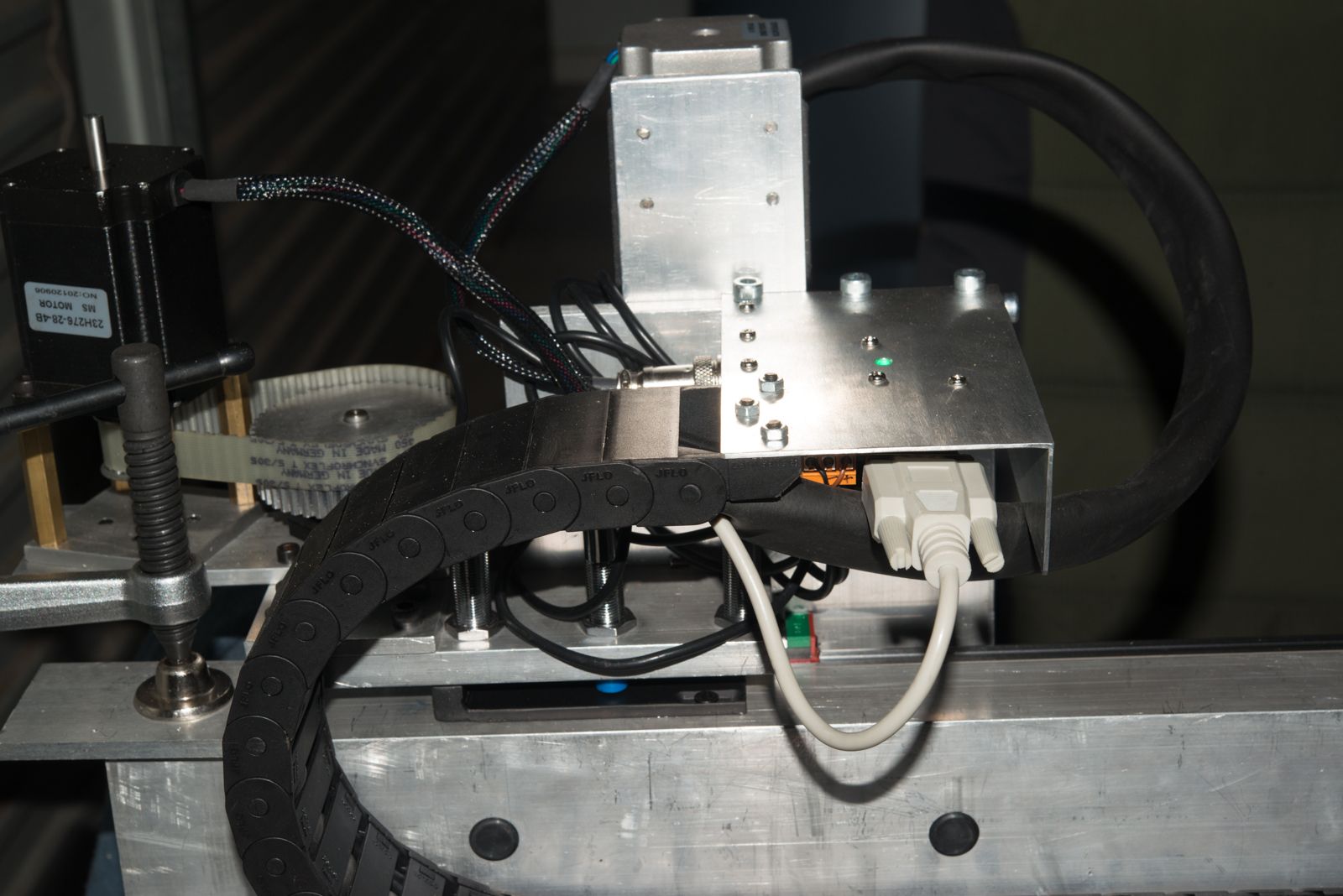
I also mounted a bracket on the gantry for the wiring for the two stepper motors.
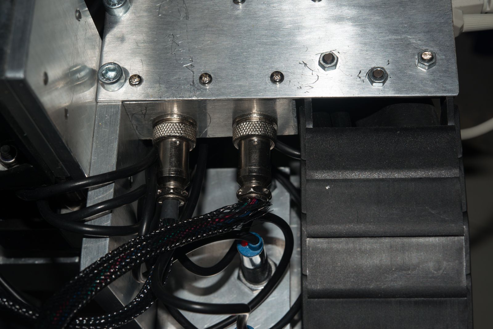
I'm using 5 pin CB microphone sockets here. At the control box end, one of the pins is used to continue the shielding on the cable right up to the stepper controllers before it is earthed to the frame.
The Y axis limits and home switches are mounted on the moving gantry
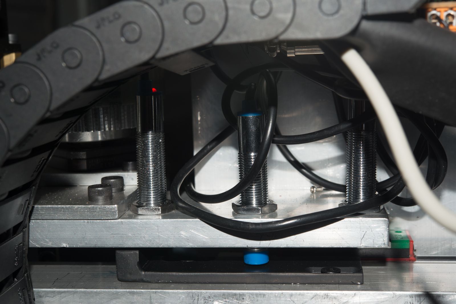
The home switch is in the centre and the sensing surface is set a lot lower than the limit sensors. Its all been a bit of a learning curve but I found that the home switches needed a fair bit of room to decelerate during the homing process but then the offset lets you place the axis where ever you like with the homing offset. I did find one trick though. If you are using a shared home/limit switch, you need to make sure the limit is not left engaged once the axis is moved to its final position as this will trigger a limit switch error once homing is complete. Cost me a bit of travel.
So here's what I came up with for the limit switches triggers. Its just a 100mm long bit of 5mm x 25mm flat steel bar with some 10mm x 10mm square bar welded on the end.
I don't really know why I bothered slotting the holes as once I worked out the position, I never had to adjust it to get it working perfectly.
This has given me 1230mm gantry travel, so plenty of room for a 1200 (4') wide sheet of steel. There is not much room for the axis to slow down if a limit switch is triggered but they stop pretty quickly.
Well thats about All I've got time for tonight but before I go, I better list the specs.
Mesa Ethernet 7i76e card
Mease THCAD for torch height control
Longs Motor DM542A stepper controllers.
Meanwell Power supplies for 48v, 24V and 5V
Z axis:
NEMA 23, 2.8 amp stepper with 150mm x 5mm pitch ball screw (with 87 mm travel) Hiwin HGR15 linear rails, floating head, magnetic breakaway, share dupper home/limit switch, dedicated lower mechanical limit switch
I've left some room on the mounting plate to mount other stuff but I'n not worrying about that right now.
Y axis
80mm x 40mm Aluminium crossmember
NEMA 23, 2.8 amp stepper motor running a 3:1 pinion drive which was discussed (and redesigned) here:
forum.linuxcnc.org/30-cnc-machines/31509...-loaded-pinion-drive
2 x HGR15 Hiwin linear rails, 1.5 module gear rack for pinion drive. If I did it again, I'd only use 1 linear rail.
Capable of running at about 21 metres per minute (call it 800" per minute if you must)
X Axis - TO DO
1600 Hiwin HGR25mm linear rails and carriages (ordered)
Cast Alloy 5:1 Timing belt driven helical pinion drives with NEMA 34 motor mounts (1 each side- ORDERED)
I was planning on using NEMA 23 steppers which I am sure I could adapt to this part but I Might bite the bullet and upgrade to NEMA 34 drives.
1600mm 1.5 module helical gear rack each side (ORDERED)
Should get around 1300-1250mm travel, enough for a half sheet
PC:
Gigabyte J1900 USFF PC, Liniux MInt, recompiled kernel, patched for the pre-emptive kernel
DELL 19" 3:4 monitor somebody left on the side of the road so I took it away.
ASUS N10 Nano USB Wifi DOngle
Running LInuxCNC MAster branch compiled for Run in Pace with much support from you guys on this thread.
forum.linuxcnc.org/9-installing-linuxcnc...ng-uspace-for-master
Well, thats about all I've got time for now.
Plasmacutter
Everlast Power Plasma 50 , 50 amp plasma cutter with CNC port and 75 amp Machine torch
I bought this as it was pretty cheap and would allow me to prove the concept. Ultimately, It may be replaced with a 3 phase unit.
Table - TO DO
Half sheet size, 1200mm x 1200mm working size
downdraft table.
Side mounted linear rails mounted on steel laser cut rails
Probably have a roll out material support so I can put a fiull sheet up on the table.
I've got some early designs of this but I have a fair bit left to rework.
Electronic Control Box
A very nice 500mm x 500mm x 200mm IP67 rated enclosure that cost me about $160
AC cooling fan
Estop controlled power outlet for table downdraft fan.
I also mounted a bracket on the gantry for the wiring for the two stepper motors.
I'm using 5 pin CB microphone sockets here. At the control box end, one of the pins is used to continue the shielding on the cable right up to the stepper controllers before it is earthed to the frame.
The Y axis limits and home switches are mounted on the moving gantry
The home switch is in the centre and the sensing surface is set a lot lower than the limit sensors. Its all been a bit of a learning curve but I found that the home switches needed a fair bit of room to decelerate during the homing process but then the offset lets you place the axis where ever you like with the homing offset. I did find one trick though. If you are using a shared home/limit switch, you need to make sure the limit is not left engaged once the axis is moved to its final position as this will trigger a limit switch error once homing is complete. Cost me a bit of travel.
So here's what I came up with for the limit switches triggers. Its just a 100mm long bit of 5mm x 25mm flat steel bar with some 10mm x 10mm square bar welded on the end.
I don't really know why I bothered slotting the holes as once I worked out the position, I never had to adjust it to get it working perfectly.
This has given me 1230mm gantry travel, so plenty of room for a 1200 (4') wide sheet of steel. There is not much room for the axis to slow down if a limit switch is triggered but they stop pretty quickly.
Well thats about All I've got time for tonight but before I go, I better list the specs.
Mesa Ethernet 7i76e card
Mease THCAD for torch height control
Longs Motor DM542A stepper controllers.
Meanwell Power supplies for 48v, 24V and 5V
Z axis:
NEMA 23, 2.8 amp stepper with 150mm x 5mm pitch ball screw (with 87 mm travel) Hiwin HGR15 linear rails, floating head, magnetic breakaway, share dupper home/limit switch, dedicated lower mechanical limit switch
I've left some room on the mounting plate to mount other stuff but I'n not worrying about that right now.
Y axis
80mm x 40mm Aluminium crossmember
NEMA 23, 2.8 amp stepper motor running a 3:1 pinion drive which was discussed (and redesigned) here:
forum.linuxcnc.org/30-cnc-machines/31509...-loaded-pinion-drive
2 x HGR15 Hiwin linear rails, 1.5 module gear rack for pinion drive. If I did it again, I'd only use 1 linear rail.
Capable of running at about 21 metres per minute (call it 800" per minute if you must)
X Axis - TO DO
1600 Hiwin HGR25mm linear rails and carriages (ordered)
Cast Alloy 5:1 Timing belt driven helical pinion drives with NEMA 34 motor mounts (1 each side- ORDERED)
I was planning on using NEMA 23 steppers which I am sure I could adapt to this part but I Might bite the bullet and upgrade to NEMA 34 drives.
1600mm 1.5 module helical gear rack each side (ORDERED)
Should get around 1300-1250mm travel, enough for a half sheet
PC:
Gigabyte J1900 USFF PC, Liniux MInt, recompiled kernel, patched for the pre-emptive kernel
DELL 19" 3:4 monitor somebody left on the side of the road so I took it away.
ASUS N10 Nano USB Wifi DOngle
Running LInuxCNC MAster branch compiled for Run in Pace with much support from you guys on this thread.
forum.linuxcnc.org/9-installing-linuxcnc...ng-uspace-for-master
Well, thats about all I've got time for now.
Plasmacutter
Everlast Power Plasma 50 , 50 amp plasma cutter with CNC port and 75 amp Machine torch
I bought this as it was pretty cheap and would allow me to prove the concept. Ultimately, It may be replaced with a 3 phase unit.
Table - TO DO
Half sheet size, 1200mm x 1200mm working size
downdraft table.
Side mounted linear rails mounted on steel laser cut rails
Probably have a roll out material support so I can put a fiull sheet up on the table.
I've got some early designs of this but I have a fair bit left to rework.
Electronic Control Box
A very nice 500mm x 500mm x 200mm IP67 rated enclosure that cost me about $160
AC cooling fan
Estop controlled power outlet for table downdraft fan.
Please Log in or Create an account to join the conversation.
- tommylight
-

- Away
- Moderator
-

Less
More
- Posts: 21714
- Thank you received: 7419
22 Dec 2016 15:26 #84556
by tommylight
Replied by tommylight on topic Rods "Spaceship" Scratch built Plasma Cutter build
Nice job, been following it all allong.
The following user(s) said Thank You: rodw
Please Log in or Create an account to join the conversation.
- rodw
-
Topic Author
- Offline
- Platinum Member
-
Less
More
- Posts: 12007
- Thank you received: 4089
23 Dec 2016 10:26 #84602
by rodw
Tommy, thanks, I can't thank you enough for your input so far but some times I've cursed you for making me work harder
But when I eventually turned my machine on it was evident your input had made an enormous difference!

So I managed to find time to take a few more pics before the sun went down.
So to finish off on the last post, I thought I'd start by showing you the sensor circuit board tucked in below my gold plated dome nuts
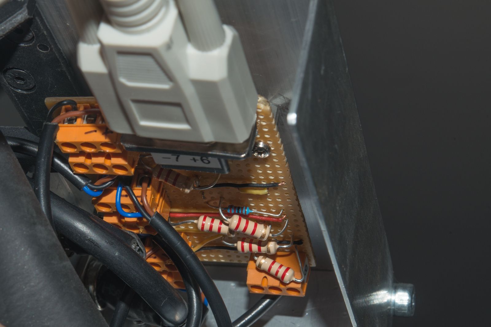
The blue resistor is the current limiting resistor for the 24 V LED indicator and you can see the orange terminal blocks. (7 of them).
The drag chain is only just big enough to hold all of the wires and it sits on some 90 x 40 x 1.6mm Angle that is fastened to the gantry lower surface using M3 drilled and tapped hole
I don't have much extra travel on the Y axis so the hard stops are when the carriage is hard up against the blocks attached at the end of the gantry.
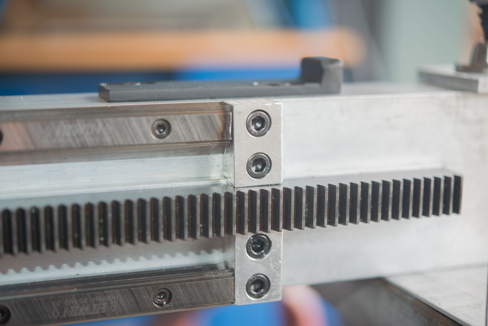
At the other end, the gear rack is not in the road so its a single piece.
Replied by rodw on topic Rods "Spaceship" Scratch built Plasma Cutter build
Nice job, been following it all allong.
Tommy, thanks, I can't thank you enough for your input so far but some times I've cursed you for making me work harder
But when I eventually turned my machine on it was evident your input had made an enormous difference!
So I managed to find time to take a few more pics before the sun went down.
So to finish off on the last post, I thought I'd start by showing you the sensor circuit board tucked in below my gold plated dome nuts
The blue resistor is the current limiting resistor for the 24 V LED indicator and you can see the orange terminal blocks. (7 of them).
The drag chain is only just big enough to hold all of the wires and it sits on some 90 x 40 x 1.6mm Angle that is fastened to the gantry lower surface using M3 drilled and tapped hole
I don't have much extra travel on the Y axis so the hard stops are when the carriage is hard up against the blocks attached at the end of the gantry.
At the other end, the gear rack is not in the road so its a single piece.
Please Log in or Create an account to join the conversation.
- rodw
-
Topic Author
- Offline
- Platinum Member
-
Less
More
- Posts: 12007
- Thank you received: 4089
23 Dec 2016 10:50 - 23 Dec 2016 10:52 #84603
by rodw
Replied by rodw on topic Rods "Spaceship" Scratch built Plasma Cutter build
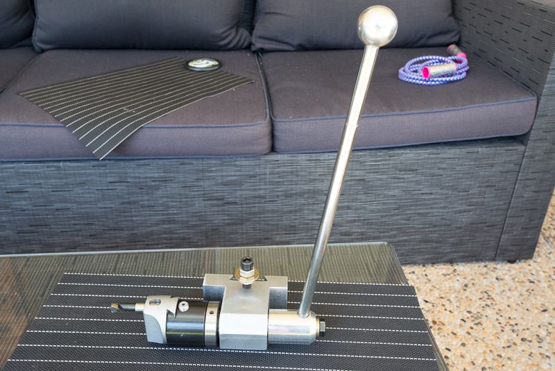
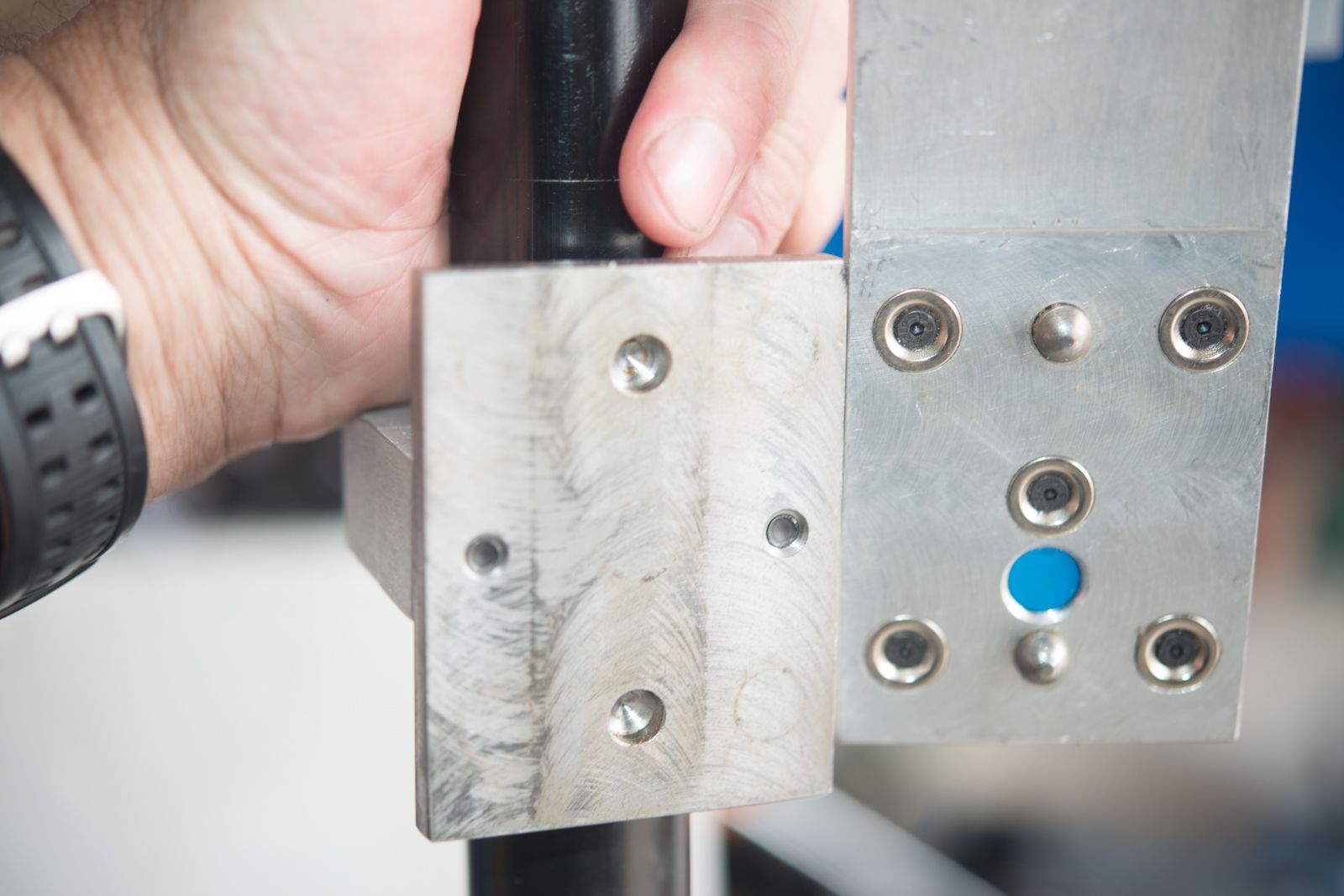
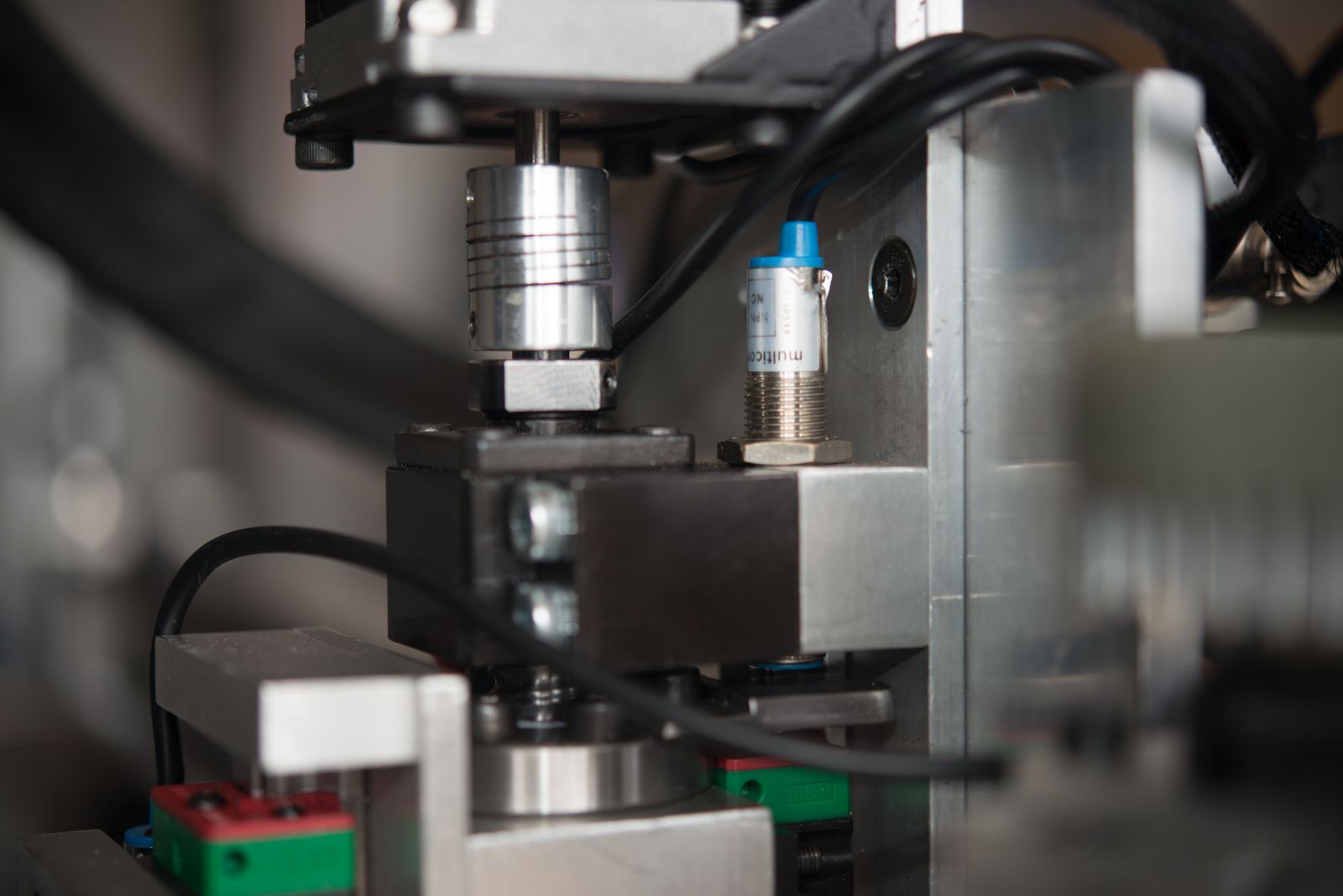
So lets have a look at the Z axis a bit more closely. I started here as I knew it was the most complex part of the build and if I could build it, I would have the confidence to build the complete table
The torch is held on by a magnetic breakaway that incorporates a Normally open Proximity sensor (becasue it is normally closed in normal operation if that makes sense.
The rounded dowels were machined on a lathe using my boring head ball turner on a manual lathe
You can see it in operation on this link
Anyway, I'm digressing, but here are both sides
The breakaway sensor is ORed with the external e-stop but I'll get to the software config later.
I need to work out how to protect the sensor as its pretty exposed.
Eventually, I'll fold up a cover to protect it and the wire. The torch is a Traffimet S75 which was provided by Everlast Australia when I purchased the plasma cutter. They said it was too expensive and did not sell many but I thought AUD $350 for a machine torch with an 8 metre lead was pretty good value.
The ballscrew nut is attached to a machined block with an obscene number of milling operations on it. I also mounted a mechanical limit switch on it. I need to swap the trigger and switch around so the wiring does not move as it does now but you live and learn!
Thats probably enough links/photos for one post. Oops, one too many so to be continued
Last edit: 23 Dec 2016 10:52 by rodw.
Please Log in or Create an account to join the conversation.
- rodw
-
Topic Author
- Offline
- Platinum Member
-
Less
More
- Posts: 12007
- Thank you received: 4089
23 Dec 2016 11:04 #84604
by rodw
Replied by rodw on topic Rods "Spaceship" Scratch built Plasma Cutter build
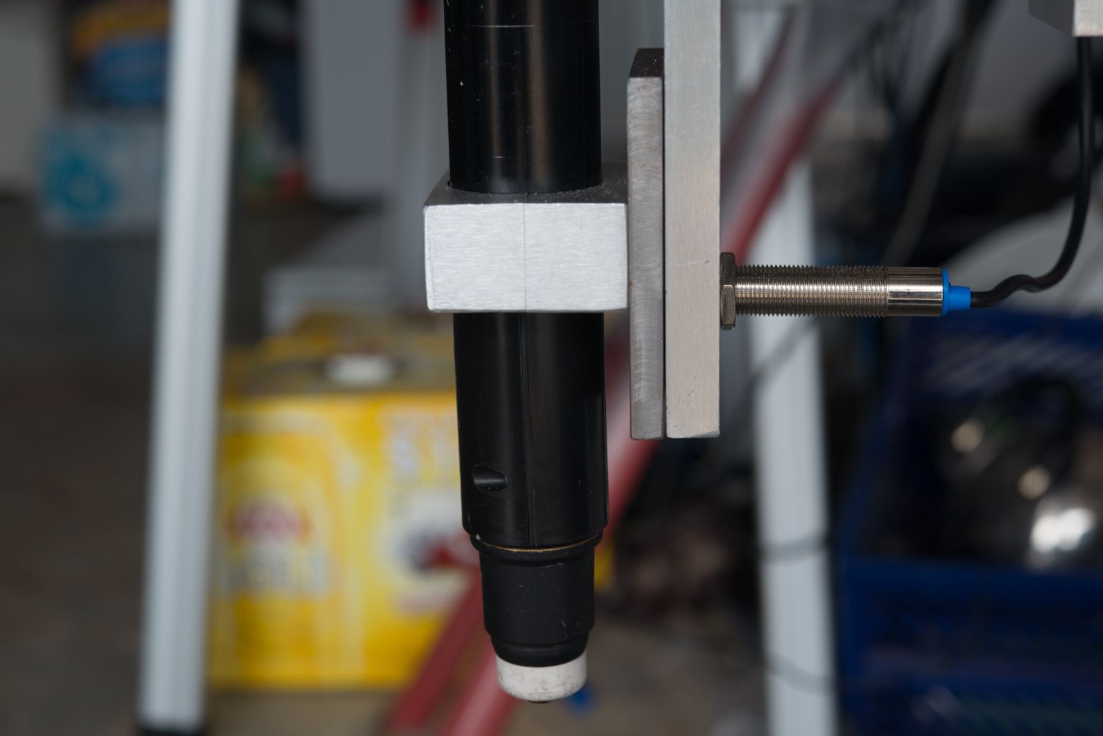
Here is the photo that I could not add to the previous post showing Z axis lower limit switch
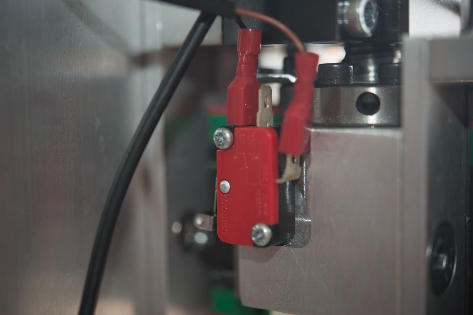
I used a mechanical switch here as it was easier to incorporate into the design and I figured that it should hardly ever get triggered if the float switch is doing its job.
The upper limit switch also doubles as a home switch as I could not see how to incorporate a separate home switch
As discussed earlier in the thread, this cost me a bit of travel on an axis that is shorter than i'd really like.
The float switch is tucked in on one side
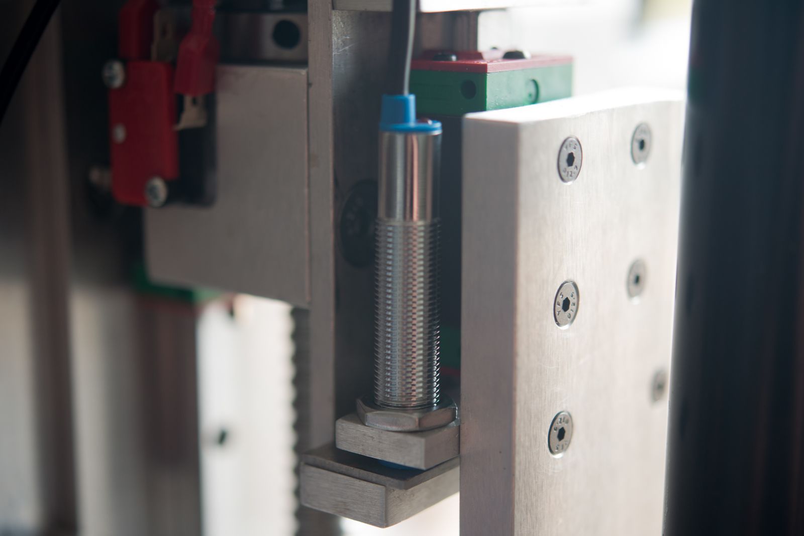
You can see that the torch rides up along the linear rail which in turn triggers the sensor. Tommy has said the limit switch need to be set so it triggers with as little movement as possible and I still need to put an adjustment in place so I have control over how far the floating torch moves. I'm hoping to get to that on the weekend provided Christmas does not intrude too much into quality shed time.
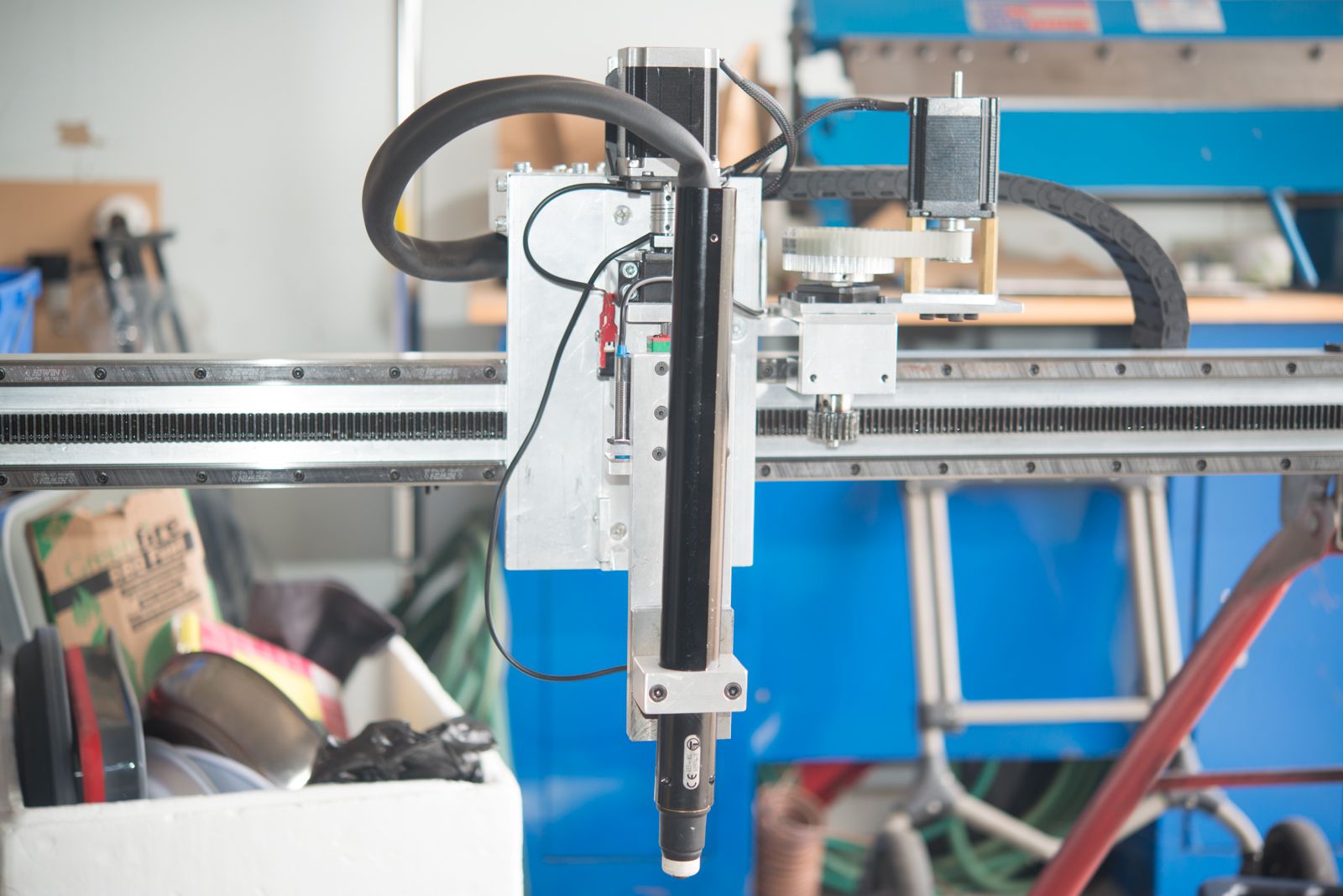
The other feature is the NEMA 23 stepper mount bracket.
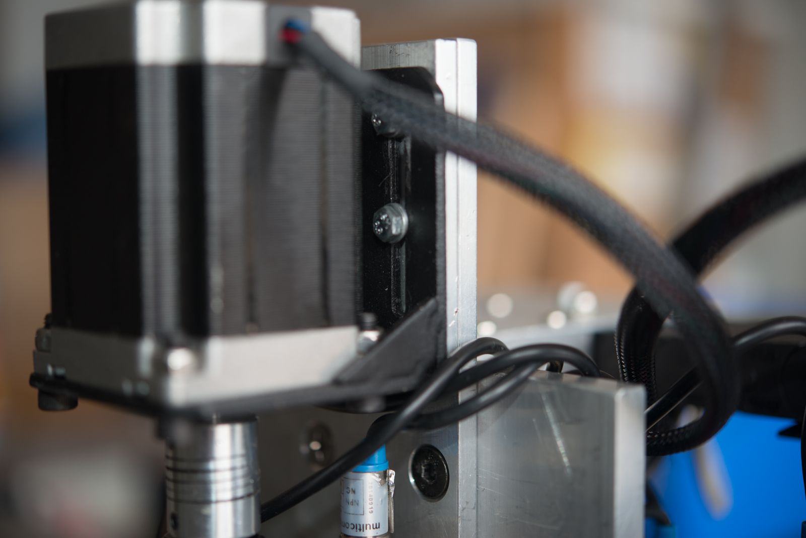
I purchased this from steppers online as it looked a lot easier to use their part than make my own bracket. I will say though that its not that good a part. It would be much nicer if it had tapped holes to mount the stepper motor.
I'm about to run out of links again and my wife has just come home so I better go at this point.
I used a mechanical switch here as it was easier to incorporate into the design and I figured that it should hardly ever get triggered if the float switch is doing its job.
The upper limit switch also doubles as a home switch as I could not see how to incorporate a separate home switch
As discussed earlier in the thread, this cost me a bit of travel on an axis that is shorter than i'd really like.
The float switch is tucked in on one side
You can see that the torch rides up along the linear rail which in turn triggers the sensor. Tommy has said the limit switch need to be set so it triggers with as little movement as possible and I still need to put an adjustment in place so I have control over how far the floating torch moves. I'm hoping to get to that on the weekend provided Christmas does not intrude too much into quality shed time.
The other feature is the NEMA 23 stepper mount bracket.
I purchased this from steppers online as it looked a lot easier to use their part than make my own bracket. I will say though that its not that good a part. It would be much nicer if it had tapped holes to mount the stepper motor.
I'm about to run out of links again and my wife has just come home so I better go at this point.
Please Log in or Create an account to join the conversation.
- rodw
-
Topic Author
- Offline
- Platinum Member
-
Less
More
- Posts: 12007
- Thank you received: 4089
23 Dec 2016 11:42 #84605
by rodw
Replied by rodw on topic Rods "Spaceship" Scratch built Plasma Cutter build
Don't you hate it when you loose a post just before you hit save?
Anyway, I wanted to show 2 more pics.
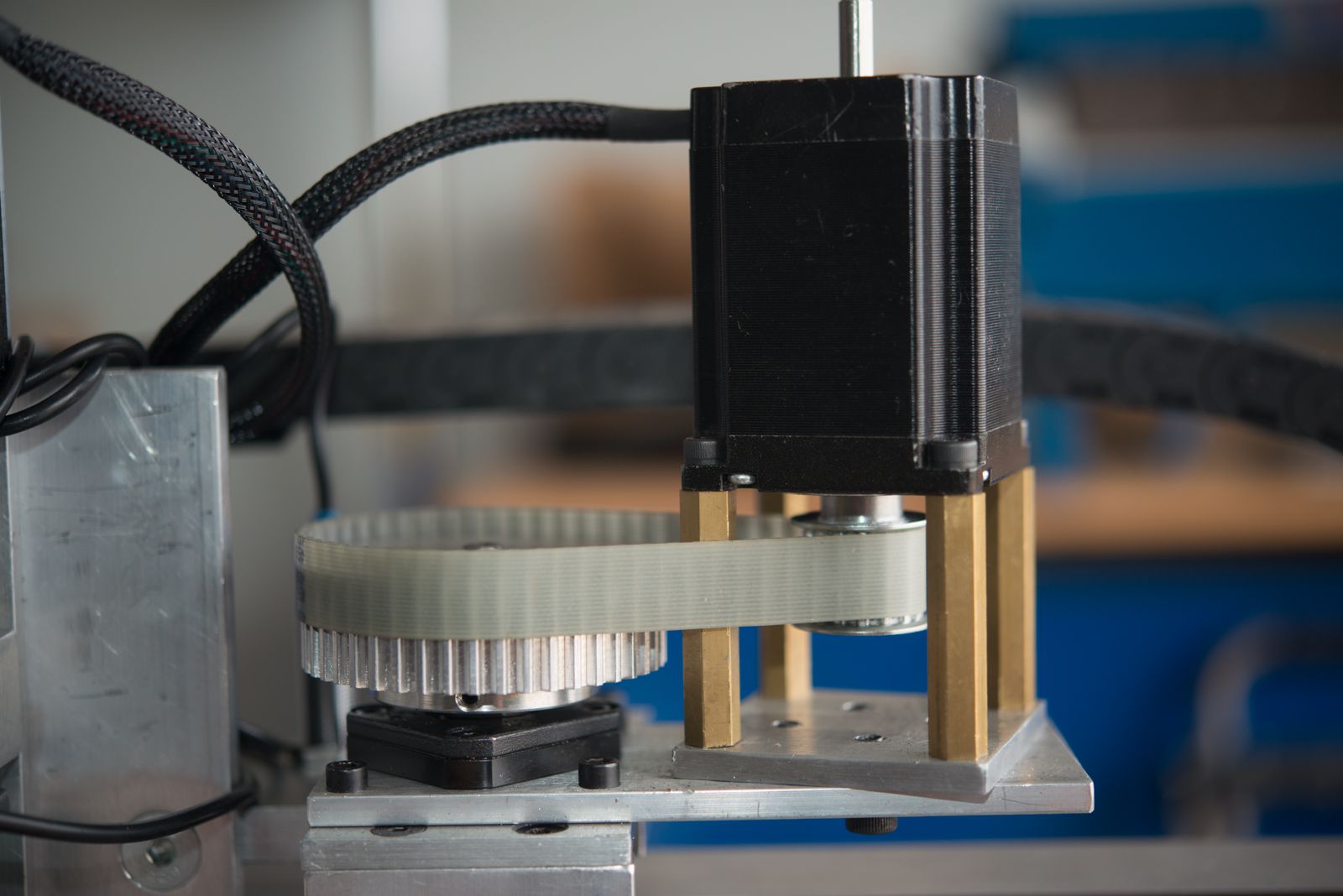
The drive pulley on the stepper has slipped so I need to shorten the brass standoff legs which won't take long.
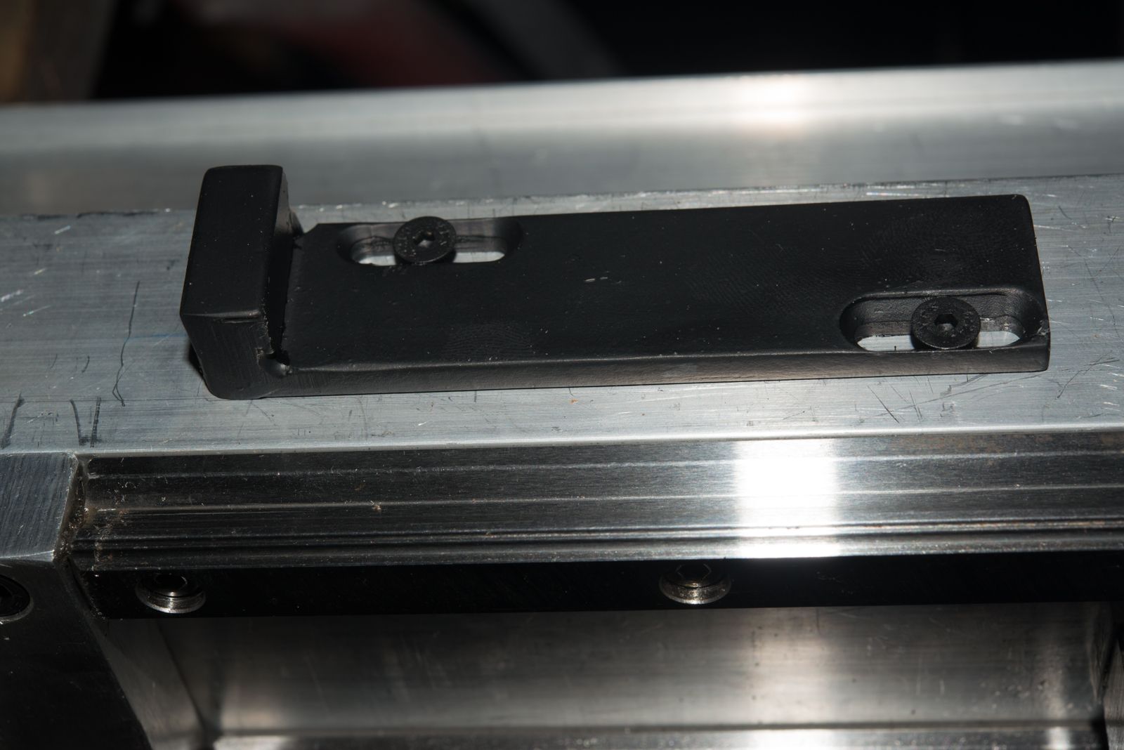
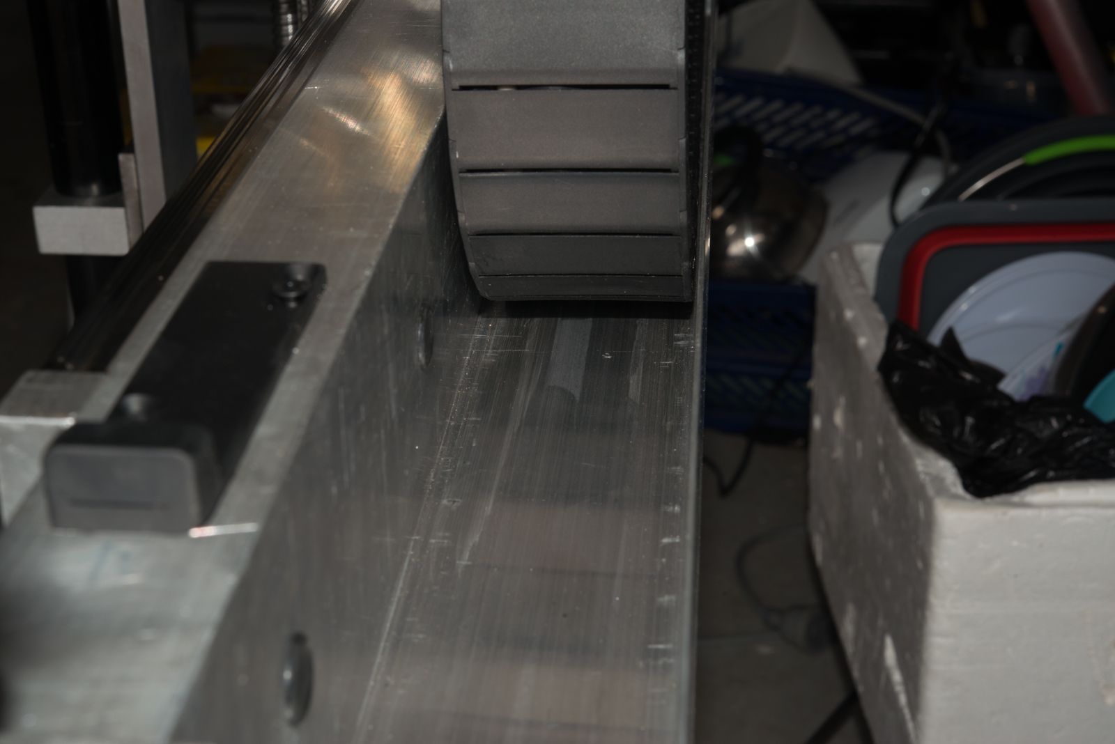
And this one of th ealuminium channel that takes over from the drag chain to protect the wiring.
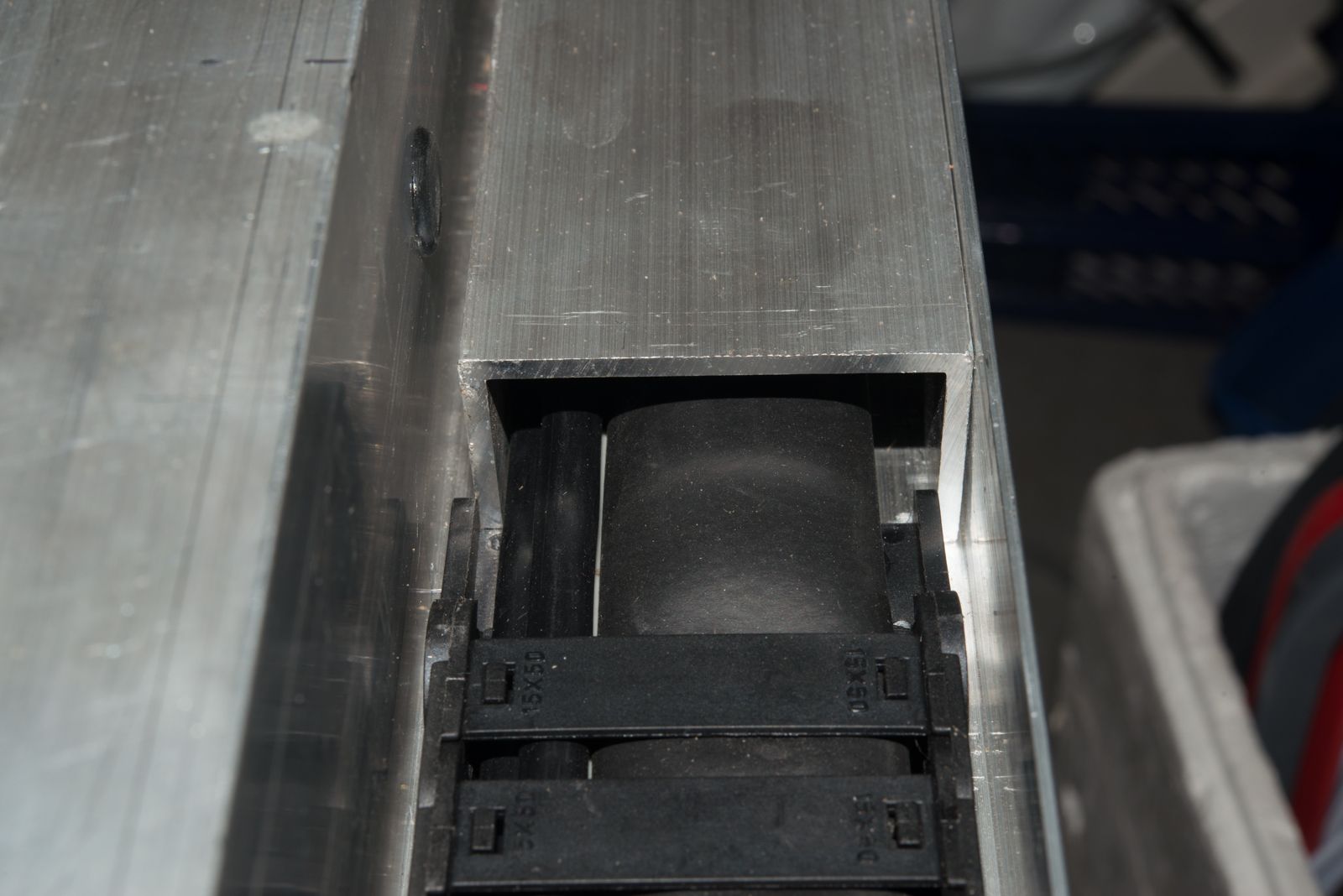
I still have to mount this part and undercut the drag chai end so the cables are not as exposed as they are in this pic.
It is worth mentioning that I've made extensive use of 60mm wide Aluminium flat bar. This easily fits in most small milling machine vices.Most material is 6mm thick but also some 12mm thick. This means this design is ideal for entry level milling machines so anybody can build this in their home workshop.
I have a Seig SX3 milling machine which has done most of the work here but there has been a little bit of lathe work machining the drive shafts. Anybody with a decent home workshop can build something like this.
So next post will cover off on the enclosure and wiring.and then we can talk about software configuration which is what tis forum is all about.
Anyway, I wanted to show 2 more pics.
The drive pulley on the stepper has slipped so I need to shorten the brass standoff legs which won't take long.
And this one of th ealuminium channel that takes over from the drag chain to protect the wiring.
I still have to mount this part and undercut the drag chai end so the cables are not as exposed as they are in this pic.
It is worth mentioning that I've made extensive use of 60mm wide Aluminium flat bar. This easily fits in most small milling machine vices.Most material is 6mm thick but also some 12mm thick. This means this design is ideal for entry level milling machines so anybody can build this in their home workshop.
I have a Seig SX3 milling machine which has done most of the work here but there has been a little bit of lathe work machining the drive shafts. Anybody with a decent home workshop can build something like this.
So next post will cover off on the enclosure and wiring.and then we can talk about software configuration which is what tis forum is all about.
Please Log in or Create an account to join the conversation.
- rodw
-
Topic Author
- Offline
- Platinum Member
-
Less
More
- Posts: 12007
- Thank you received: 4089
24 Dec 2016 07:47 #84668
by rodw
Replied by rodw on topic Rods "Spaceship" Scratch built Plasma Cutter build
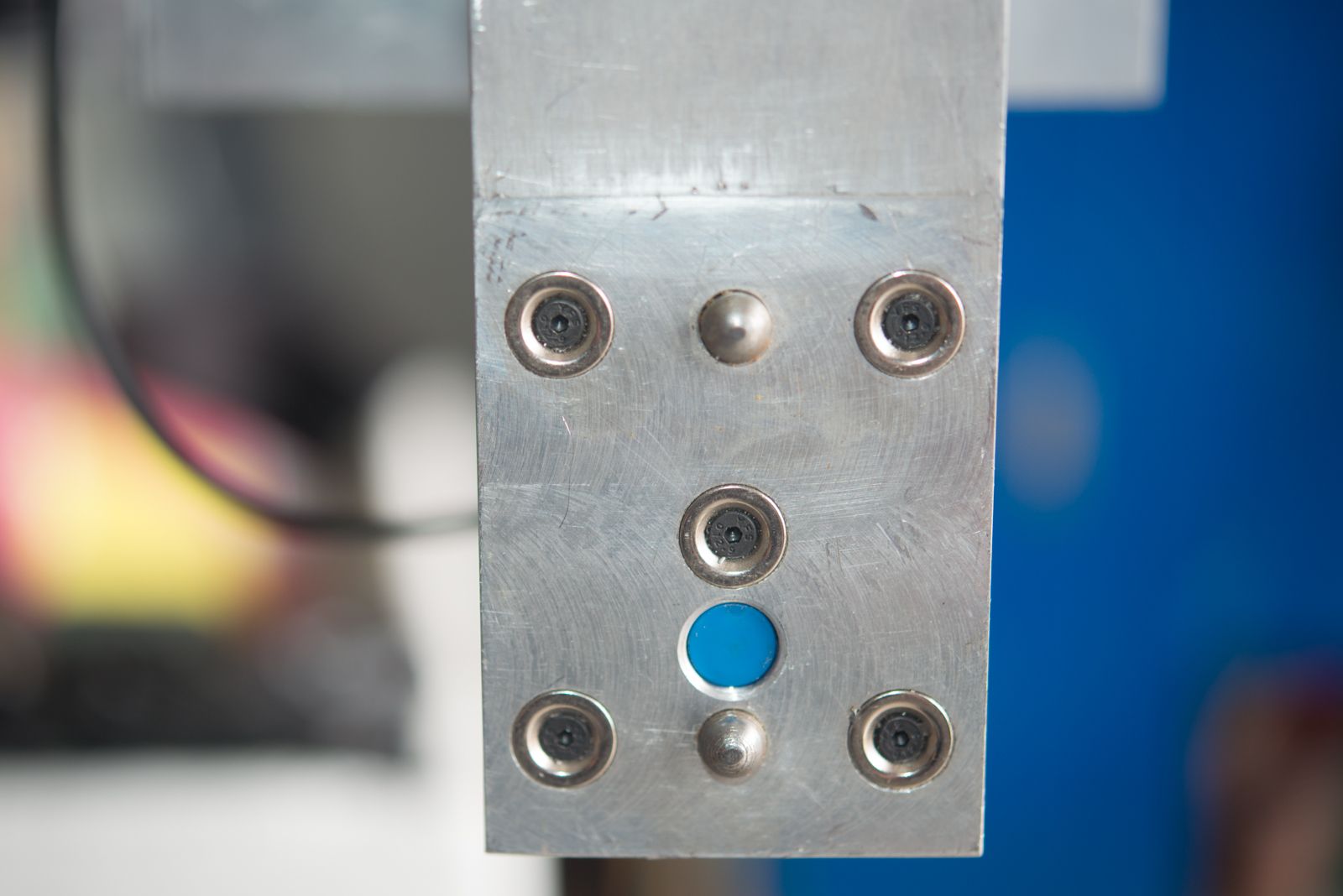
I only got an hour or so to play today but I added an adjustment screw to control the float switch movement. All I did was remove the part the sensor is mounted to and drill and tap an M4 hole for a countersunk screw and lock nut.
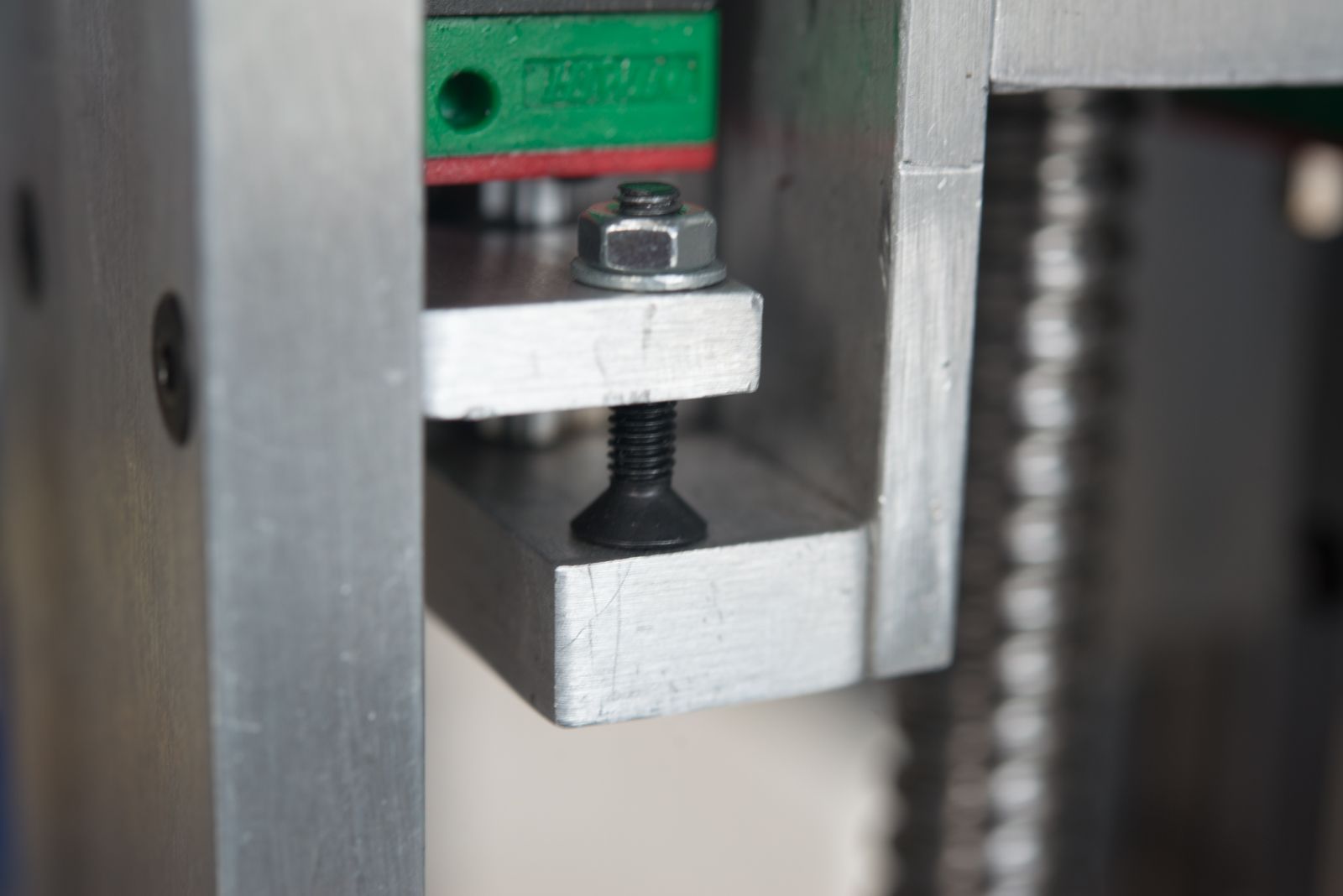
I did think of turning up a knurled knob but the M4 screw will do the job just as well. If I get too much wear in the aluminium, I'll add a countersink screw in the bottom part to act as a metal seat.
I have not measured the movement precisely but I would say movement of well under 0.5 mm will trigger the float sensor.. I'll revisit this when I get the float switch input actually doing something useful in the software.
Please Log in or Create an account to join the conversation.
- rodw
-
Topic Author
- Offline
- Platinum Member
-
Less
More
- Posts: 12007
- Thank you received: 4089
27 Dec 2016 06:17 #84737
by rodw
Replied by rodw on topic Rods "Spaceship" Scratch built Plasma Cutter build
Well I solved a problem today that had been bugging me for 18 months or more and was the impetus that made me upgrade to a Mesa ethernet card.
You see, back then I built a plasma CNC controller back then and shoehorned it into an old Plasma case
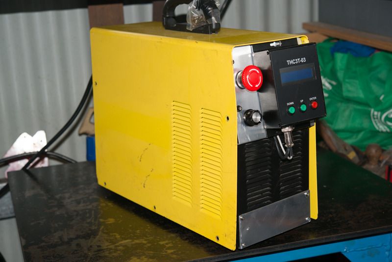
I could never get it going and put it down to experience and tore it apart at the beginning of this build.
Anyway, becasue I am still waiting for my motion control hardware to arrive, I decided to reinstall LinuxCNC on the MiniBox PC I have. Once again I had no luck but realised that the real problem was that the ribbon cable I made had the connectors round the wrong way.
I tried to correct the problem but I never have much luck modifying ribbon cable connectors and yesterday was no exception. I ended up ordering a new on of eBay but emailed my mate Chris to see if he had a spare. Turns out he didn't but my query motivated him into finally making a longer cable for his Smoothstepper on his mill so he gave me the old one.
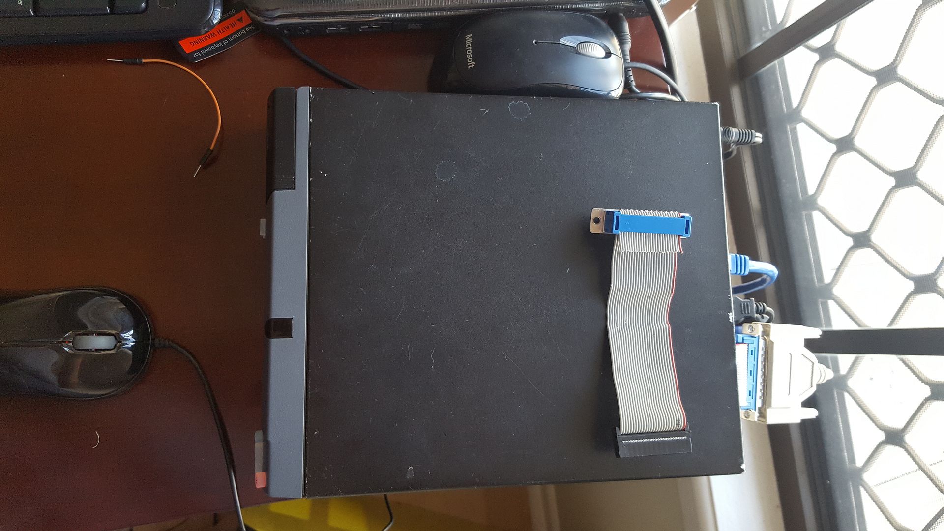
He knows a lot more about electronics than I do and we bench tested my cheap Chinese breakout board and confirmed it was working perfectly and the signals and LCNC is seeing both inputs and outputs. Anyway, once I got it home, his old ribbon cable worked a treat. Everything is running perfect on the breakout board now.
The old VIA motherboard has latency of about 18000 so I think it will be fine for when I'm ready to make another CNC machine. Actually, I have my eye on a converted Seig X3 mill but really think I'll struggle to house it and a plasma table in the garage.
I did do a bit more work on wiring the controller up including the torch on relay and THC input. I added a LED light for the torch and a switch to simulate the ArcOK signal but still have to tackle the wiring.
From the UPS tracking, it looks like my linear rails and carriages are now in the country and the gear racks and stepper gear boxes are somewhere between Singapore and Australia. I spent a bit of time last night designing the gantry end plates. The plan is to have it all designed in the next week or so so I can send the parts out for laser cutting when my suppliers get back in the new year.
You see, back then I built a plasma CNC controller back then and shoehorned it into an old Plasma case
I could never get it going and put it down to experience and tore it apart at the beginning of this build.
Anyway, becasue I am still waiting for my motion control hardware to arrive, I decided to reinstall LinuxCNC on the MiniBox PC I have. Once again I had no luck but realised that the real problem was that the ribbon cable I made had the connectors round the wrong way.
I tried to correct the problem but I never have much luck modifying ribbon cable connectors and yesterday was no exception. I ended up ordering a new on of eBay but emailed my mate Chris to see if he had a spare. Turns out he didn't but my query motivated him into finally making a longer cable for his Smoothstepper on his mill so he gave me the old one.
He knows a lot more about electronics than I do and we bench tested my cheap Chinese breakout board and confirmed it was working perfectly and the signals and LCNC is seeing both inputs and outputs. Anyway, once I got it home, his old ribbon cable worked a treat. Everything is running perfect on the breakout board now.
The old VIA motherboard has latency of about 18000 so I think it will be fine for when I'm ready to make another CNC machine. Actually, I have my eye on a converted Seig X3 mill but really think I'll struggle to house it and a plasma table in the garage.
I did do a bit more work on wiring the controller up including the torch on relay and THC input. I added a LED light for the torch and a switch to simulate the ArcOK signal but still have to tackle the wiring.
From the UPS tracking, it looks like my linear rails and carriages are now in the country and the gear racks and stepper gear boxes are somewhere between Singapore and Australia. I spent a bit of time last night designing the gantry end plates. The plan is to have it all designed in the next week or so so I can send the parts out for laser cutting when my suppliers get back in the new year.
Please Log in or Create an account to join the conversation.
- rodw
-
Topic Author
- Offline
- Platinum Member
-
Less
More
- Posts: 12007
- Thank you received: 4089
28 Dec 2016 07:16 #84793
by rodw
Replied by rodw on topic Rods "Spaceship" Scratch built Plasma Cutter build
Well, reality won. I didn't buy that mill so its back onto the plasma table. I just did not have room for it.
This morning was quite a momentous occasion as after 6 months, I was finally able to join the gantry to the table in my 3D model.
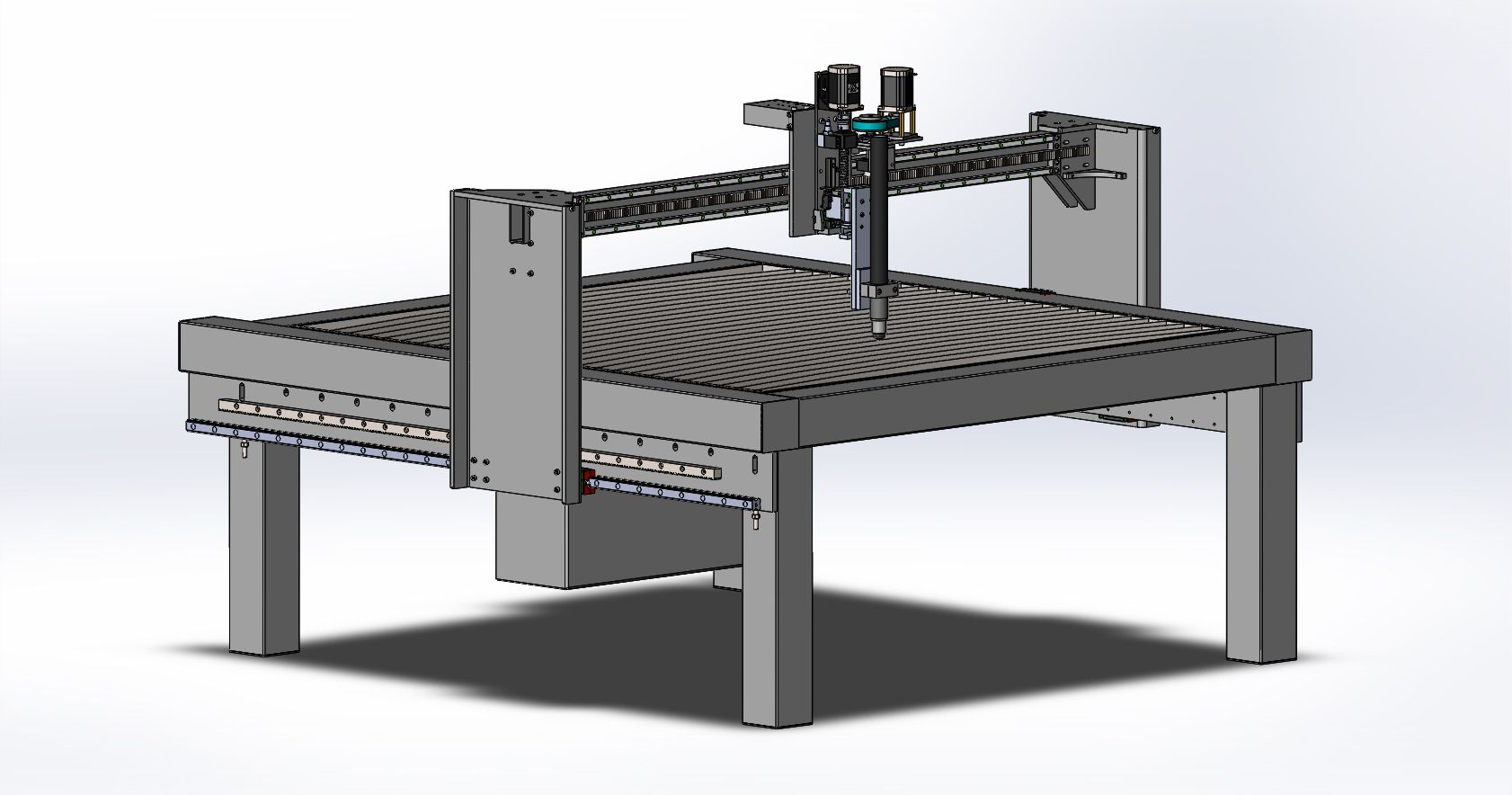
As it stands, the model has a water tray but I really would like to build a downdraft table and have some ideas on that.
There is still a bit of work to do including mounting the X axis stepper motors but It will come together pretty quick from here. Most of the parts will be CNC laser cut using steel for the table and aluminium for the gantry ends. The gantry ends will have a folded return on the edges for stiffness. I will probably also add some stiffening braces on the outer sides of the gantry.
Both shipments of linear rails and racks are set for delivery tomorrow, so I should be able to finish off designing the main parts once I can check some dimensions.
I also managed to wire up and test the ArcOk signal and the torch on switch today and an M3 command made a very satisfying click of a relay which turned on a light I'd rigged up that will be replaced with the torch switch. My manual ArcOk test switch is also being read and switches on a light on the control panel.
I'm sure I'll have a lot of questions on the software side of things once I start configuring LinuxCNC so please keep following along.
One thing I don't really get is how to use a signal more than once. eg. how to use the ArcOk input to turn on an indicator light AND trigger a light attached to an output.
This morning was quite a momentous occasion as after 6 months, I was finally able to join the gantry to the table in my 3D model.
As it stands, the model has a water tray but I really would like to build a downdraft table and have some ideas on that.
There is still a bit of work to do including mounting the X axis stepper motors but It will come together pretty quick from here. Most of the parts will be CNC laser cut using steel for the table and aluminium for the gantry ends. The gantry ends will have a folded return on the edges for stiffness. I will probably also add some stiffening braces on the outer sides of the gantry.
Both shipments of linear rails and racks are set for delivery tomorrow, so I should be able to finish off designing the main parts once I can check some dimensions.
I also managed to wire up and test the ArcOk signal and the torch on switch today and an M3 command made a very satisfying click of a relay which turned on a light I'd rigged up that will be replaced with the torch switch. My manual ArcOk test switch is also being read and switches on a light on the control panel.
I'm sure I'll have a lot of questions on the software side of things once I start configuring LinuxCNC so please keep following along.
One thing I don't really get is how to use a signal more than once. eg. how to use the ArcOk input to turn on an indicator light AND trigger a light attached to an output.
Please Log in or Create an account to join the conversation.
Time to create page: 0.168 seconds