Rods "Spaceship" Scratch built Plasma Cutter build
- rodw
-
 Topic Author
- Away
- Platinum Member
-

Less
More
- Posts: 12024
- Thank you received: 4100
14 Jan 2017 11:24 #85738
by rodw
Replied by rodw on topic Rods "Spaceship" Scratch built Plasma Cutter build
Racedirector said it was 46 degrees in his shed today and I'd believe it! My weather station only registered 36 degrees here today but in a courrugated iron combination shed/sauna, I'm sure it would have been 46 degrees where I was working...
Anyway, got the X axis stepper motors mounted up
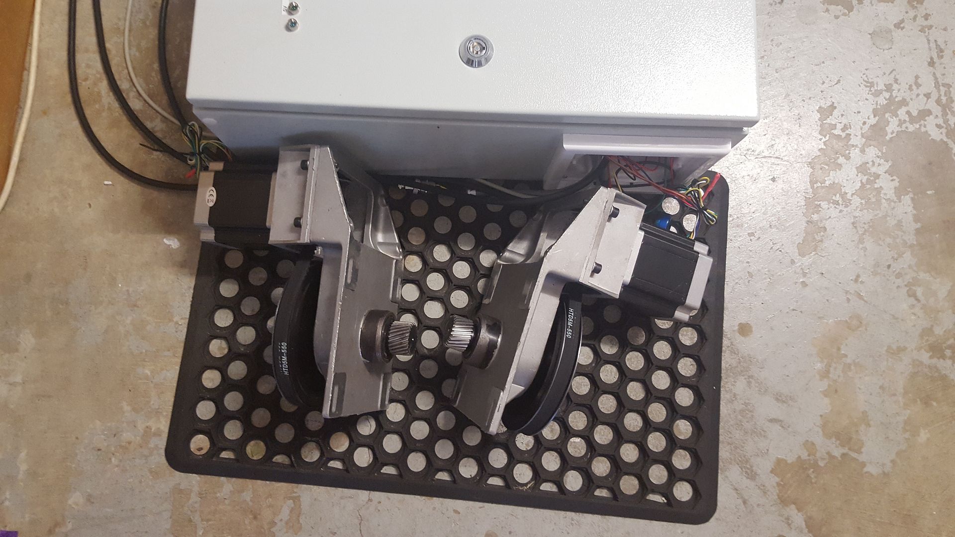
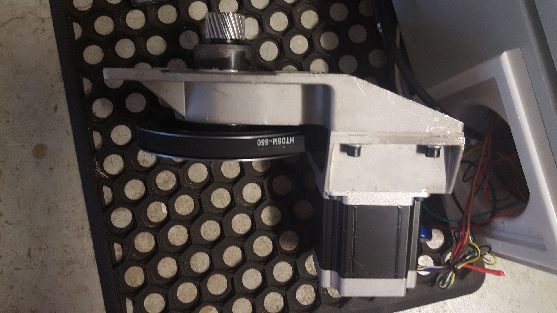
This time, I had the config sorted OK and they worked straight away. Its going to be hard to wait out the time until my gantry ends to arrive.
I've been doing a bit of research on torch height control and I found a journal article that said torch voltage varied during a cut as the "anode spot" (being the opposite and of the arc to the torch tip) varies up and down through the thickness of the material during the cut. They found with some signal processing there was a linear relationship between minimum voltage (eg when the anode spot was closest to the torch - eg. at the upper surface). I'd like to experiment with this but I think with the PC hardware I have has too much latency to sample fast enough to implement their algorithm.
Anyway, they found that there was a ripple in the voltage signal becasue the voltage was sourced from a 60 Hz 3 phase AC power source at around 360 Hz so they needed to ensure that the sample period was large enough to capture this voltage spike and they settled on 40 milliseconds. But to find the lowest voltage, they sampled at 40 microseconds. eg they take 1000 samples per 40 milliseconds and save the lowest voltage they find! So if you are using a 50 Hz single phase plasma cutter like me, I think the rectification ripple will be at 100 Hz (eg. 2x the AC frequency per phase)
So this got me thinking about redirecting the THCAD frequency output to an Arduino to do the signal processing before sending the processed minimum voltage to LCNC. It certainly can handle the 40 usec sampling period and in fact you can prescale the Arduino clock to run an interrupt at at 4 usec so sampling can be done every 10 clock cycles. Nice and simple!
Anyway, when I get this working the next step is to get the processed signal to LCNC. I think the best way would be to just send the processed signal onto LCNC by outputting a modified/corrected frequency that substitutes the THCAD output. The alternative would be to send a numeric value back to LCNC but I'm not sure if that that can be achieved in the timings we need to meet (but the servo thread is quite a bit slower than the sample timings! Any ideas on how best to tell LCNC the arc voltage would be appreciated.
Anyway, got the X axis stepper motors mounted up
This time, I had the config sorted OK and they worked straight away. Its going to be hard to wait out the time until my gantry ends to arrive.
I've been doing a bit of research on torch height control and I found a journal article that said torch voltage varied during a cut as the "anode spot" (being the opposite and of the arc to the torch tip) varies up and down through the thickness of the material during the cut. They found with some signal processing there was a linear relationship between minimum voltage (eg when the anode spot was closest to the torch - eg. at the upper surface). I'd like to experiment with this but I think with the PC hardware I have has too much latency to sample fast enough to implement their algorithm.
Anyway, they found that there was a ripple in the voltage signal becasue the voltage was sourced from a 60 Hz 3 phase AC power source at around 360 Hz so they needed to ensure that the sample period was large enough to capture this voltage spike and they settled on 40 milliseconds. But to find the lowest voltage, they sampled at 40 microseconds. eg they take 1000 samples per 40 milliseconds and save the lowest voltage they find! So if you are using a 50 Hz single phase plasma cutter like me, I think the rectification ripple will be at 100 Hz (eg. 2x the AC frequency per phase)
So this got me thinking about redirecting the THCAD frequency output to an Arduino to do the signal processing before sending the processed minimum voltage to LCNC. It certainly can handle the 40 usec sampling period and in fact you can prescale the Arduino clock to run an interrupt at at 4 usec so sampling can be done every 10 clock cycles. Nice and simple!
Anyway, when I get this working the next step is to get the processed signal to LCNC. I think the best way would be to just send the processed signal onto LCNC by outputting a modified/corrected frequency that substitutes the THCAD output. The alternative would be to send a numeric value back to LCNC but I'm not sure if that that can be achieved in the timings we need to meet (but the servo thread is quite a bit slower than the sample timings! Any ideas on how best to tell LCNC the arc voltage would be appreciated.
Please Log in or Create an account to join the conversation.
- rodw
-
Topic Author
- Away
- Platinum Member
-
Less
More
- Posts: 12024
- Thank you received: 4100
15 Jan 2017 10:52 #85811
by rodw
Replied by rodw on topic Rods "Spaceship" Scratch built Plasma Cutter build
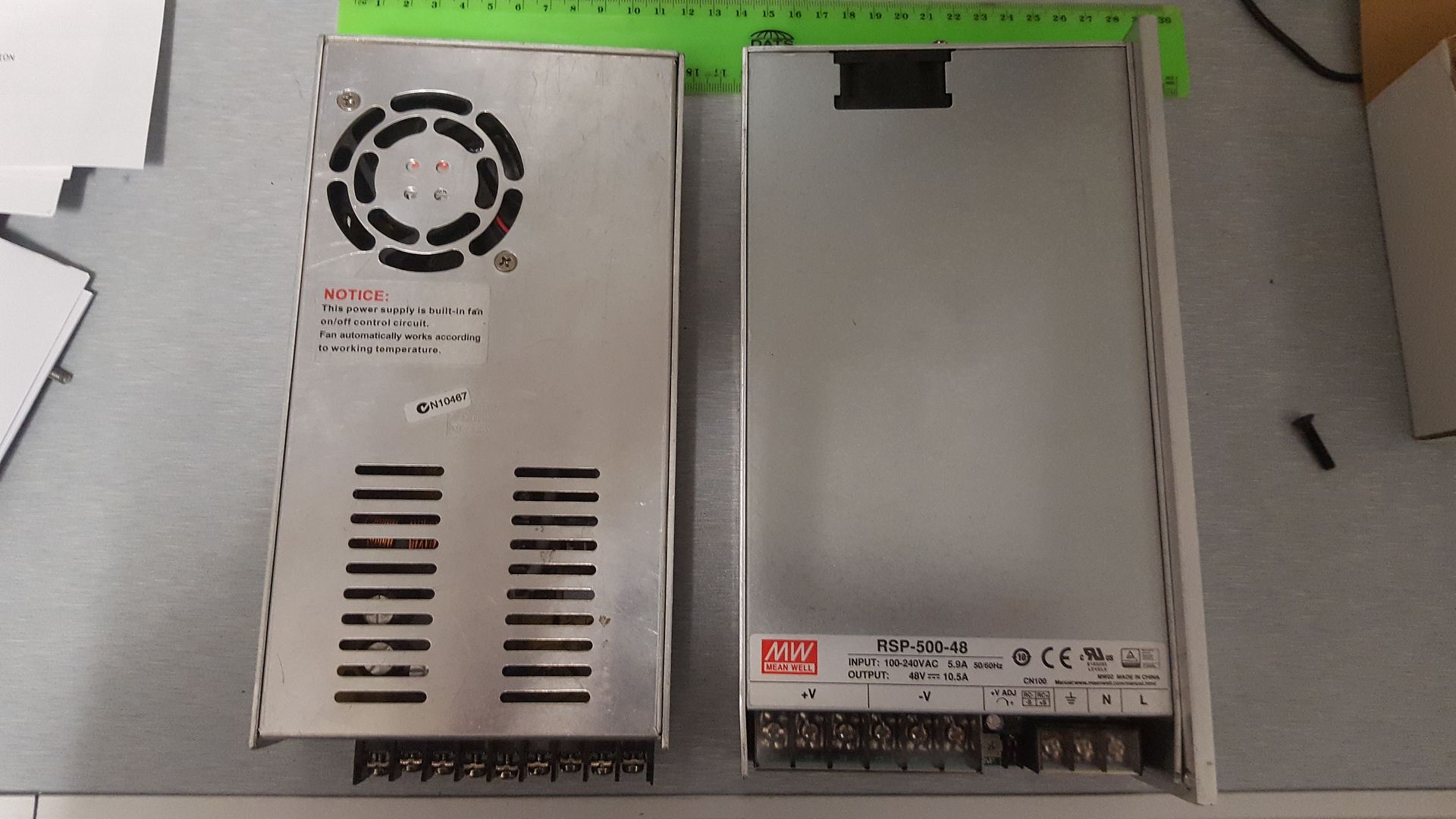
Not happy here today. I managed to fit an upgraded power supply and it was so hot, I had to wipe out the sweat in the enclosure before I was game to turn the power on.
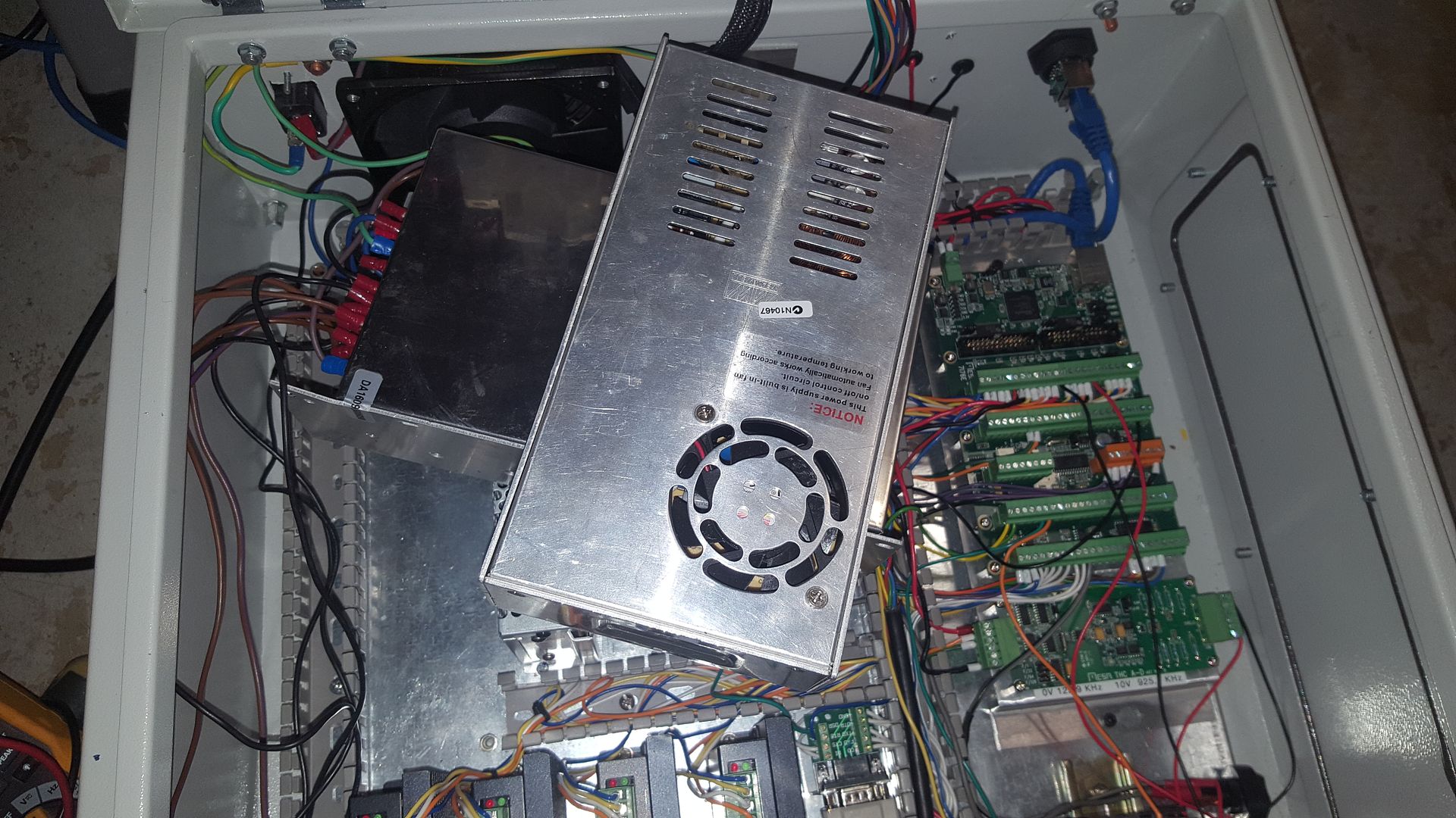
Once I did, I found the new 10.5 amp supply (on the bottom) was dead on arrival. I bought it with my NEMA 34 steppers because I need more power. This one only cost USD $45 so hopefully, they will send me a new one.
I also ordered 6 proximity sensors. I could not find a well priced eBay source so I ended up spending $140 for normally closed PNP sensors..
ON one bright note, I managed to move from the axis GUI to gmoccapy and I found it surprisingly easy until I tried to hook up the THC to the gmoccapy plasma module and could not work it out. I've asked for some help on another thread so hopefully I will sort it out.
forum.linuxcnc.org/gmoccapy/32164-plasma-component-in-gmoccapy
The other problem since I tidied up all my axes is that while the home switches all work, on a G28, I get an error that the Z axis can't go beyond its limits and it errors This was there in axis. I don't understand this as it happens even if the Z axis is already homed.
Please Log in or Create an account to join the conversation.
- andypugh
-

- Offline
- Moderator
-

Less
More
- Posts: 19875
- Thank you received: 4642
15 Jan 2017 15:34 #85820
by andypugh
If you can write Arduino code to do the job then you can write a custom HAL component to do the same job.
Replied by andypugh on topic Rods "Spaceship" Scratch built Plasma Cutter build
So this got me thinking about redirecting the THCAD frequency output to an Arduino to do the signal processing before sending the processed minimum voltage to LCNC.
If you can write Arduino code to do the job then you can write a custom HAL component to do the same job.
Please Log in or Create an account to join the conversation.
- rodw
-
Topic Author
- Away
- Platinum Member
-
Less
More
- Posts: 12024
- Thank you received: 4100
15 Jan 2017 20:37 - 15 Jan 2017 20:39 #85849
by rodw
Andy, I absolutely agree and that would be my preferred option. I thought the servo thread created in the line below ran 1000 times per second (or every millisecond)
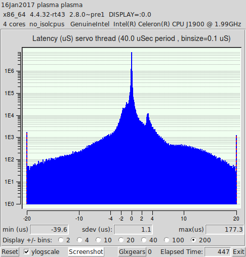
I need a thread that runs at 40 usec and my base jitter according to latency-test on a 25 usec timing is sitting on about 140,000. Is the hardware good enough is really the first question.
Replied by rodw on topic Rods "Spaceship" Scratch built Plasma Cutter build
So this got me thinking about redirecting the THCAD frequency output to an Arduino to do the signal processing before sending the processed minimum voltage to LCNC.
If you can write Arduino code to do the job then you can write a custom HAL component to do the same job.
Andy, I absolutely agree and that would be my preferred option. I thought the servo thread created in the line below ran 1000 times per second (or every millisecond)
loadrt [EMCMOT]EMCMOT servo_period_nsec=[EMCMOT]SERVO_PERIOD num_joints=[KINS]JOINTSI need a thread that runs at 40 usec and my base jitter according to latency-test on a 25 usec timing is sitting on about 140,000. Is the hardware good enough is really the first question.
Last edit: 15 Jan 2017 20:39 by rodw.
Please Log in or Create an account to join the conversation.
- rodw
-
Topic Author
- Away
- Platinum Member
-
Less
More
- Posts: 12024
- Thank you received: 4100
15 Jan 2017 21:00 #85851
by rodw
Replied by rodw on topic Rods "Spaceship" Scratch built Plasma Cutter build
Cool, latency-histogram lets you define a thread time period. First time I've used it.
Maybe that will help...
Maybe that will help...
Please Log in or Create an account to join the conversation.
- PCW
-

- Away
- Moderator
-
Less
More
- Posts: 17985
- Thank you received: 5277
15 Jan 2017 21:12 #85852
by PCW
Replied by PCW on topic Rods "Spaceship" Scratch built Plasma Cutter build
Note that you cannot use the THCAD for fast conversions (if you sample at 40 KHz you will get only about 5 bits of resolution)
Its conceivable to use a Arduinos A-D and capture the minimum value, though I do suspect you would need better torch power to make this of any use as the combination of ripple, hash from the plasmas switching power supply and probalems getting enough common mode rejection with the required input circuitry would mean you get a very high noise to signal ratio
(I suspect you have the fine sandpaper out when a chain saw is in order)
Please Log in or Create an account to join the conversation.
- tommylight
-

- Away
- Moderator
-
Less
More
- Posts: 21734
- Thank you received: 7425
15 Jan 2017 21:15 #85853
by tommylight
Replied by tommylight on topic Rods "Spaceship" Scratch built Plasma Cutter build
Do not take my word for it, but that does not look very good. Usable, most probably.
I gave my brother a Fujitsu Siemens Celsius workstation that makes some nice narrow spikes in the rangege of under 3000, now i have to find a way to take it back nicely. It is an 8 Xeon processor, 16GB ram, 2 RAID contoller monster, although several years old.
Did you get the laser cut parts?
I gave my brother a Fujitsu Siemens Celsius workstation that makes some nice narrow spikes in the rangege of under 3000, now i have to find a way to take it back nicely. It is an 8 Xeon processor, 16GB ram, 2 RAID contoller monster, although several years old.
Did you get the laser cut parts?
Please Log in or Create an account to join the conversation.
- rodw
-
Topic Author
- Away
- Platinum Member
-
Less
More
- Posts: 12024
- Thank you received: 4100
15 Jan 2017 21:51 #85858
by rodw
Peter, Thanks. The other thing I didn't understand was the recommendation run the THCAD at 1/32 for LCNC.
Thats what I thought hence suggesting an Arduino frequency counter to read THCAD and then output a processed frequency signal using another interrupt service routine to THC so LCNC would not even know the Arduino was there... But 5 bits of resolution is a bit of a worry.
The laser is still coming.... Very impatient here...
Replied by rodw on topic Rods "Spaceship" Scratch built Plasma Cutter build
Note that you cannot use the THCAD for fast conversions (if you sample at 40 KHz you will get only about 5 bits of resolution)
Its conceivable to use a Arduinos A-D and capture the minimum value, though I do suspect you would need better torch power to make this of any use as the combination of ripple, hash from the plasmas switching power supply and probalems getting enough common mode rejection with the required input circuitry would mean you get a very high noise to signal ratio
(I suspect you have the fine sandpaper out when a chain saw is in order)
Peter, Thanks. The other thing I didn't understand was the recommendation run the THCAD at 1/32 for LCNC.
Do not take my word for it, but that does not look very good. Usable, most probably.
I gave my brother a Fujitsu Siemens Celsius workstation that makes some nice narrow spikes in the rangege of under 3000, now i have to find a way to take it back nicely. It is an 8 Xeon processor, 16GB ram, 2 RAID contoller monster, although several years old.
Did you get the laser cut parts?
Thats what I thought hence suggesting an Arduino frequency counter to read THCAD and then output a processed frequency signal using another interrupt service routine to THC so LCNC would not even know the Arduino was there... But 5 bits of resolution is a bit of a worry.
The laser is still coming.... Very impatient here...
Please Log in or Create an account to join the conversation.
- rodw
-
Topic Author
- Away
- Platinum Member
-
Less
More
- Posts: 12024
- Thank you received: 4100
18 Jan 2017 12:10 - 18 Jan 2017 12:11 #86043
by rodw
Replied by rodw on topic Rods "Spaceship" Scratch built Plasma Cutter build
Progress has been slow this week but on the brighter side, my PNP normally closed proximity switches arrived. These will be fitted to the gantry ends, 3 each side.
Also steppers online's returns policy means I only have to post the faulty power supply to an Australian address for replacement. They've given me a RO number. It seems it will join the ranks of surplus equipment I've accumulated during this project because a replacement Meanwell power supply arrived from Power Supplies Australia . I've used these guys several times now and they provide really good service.
So here is the working 7.5 amp 48 volt supply I removed on the left beside the newer slimline 10.5 amp one on the right.
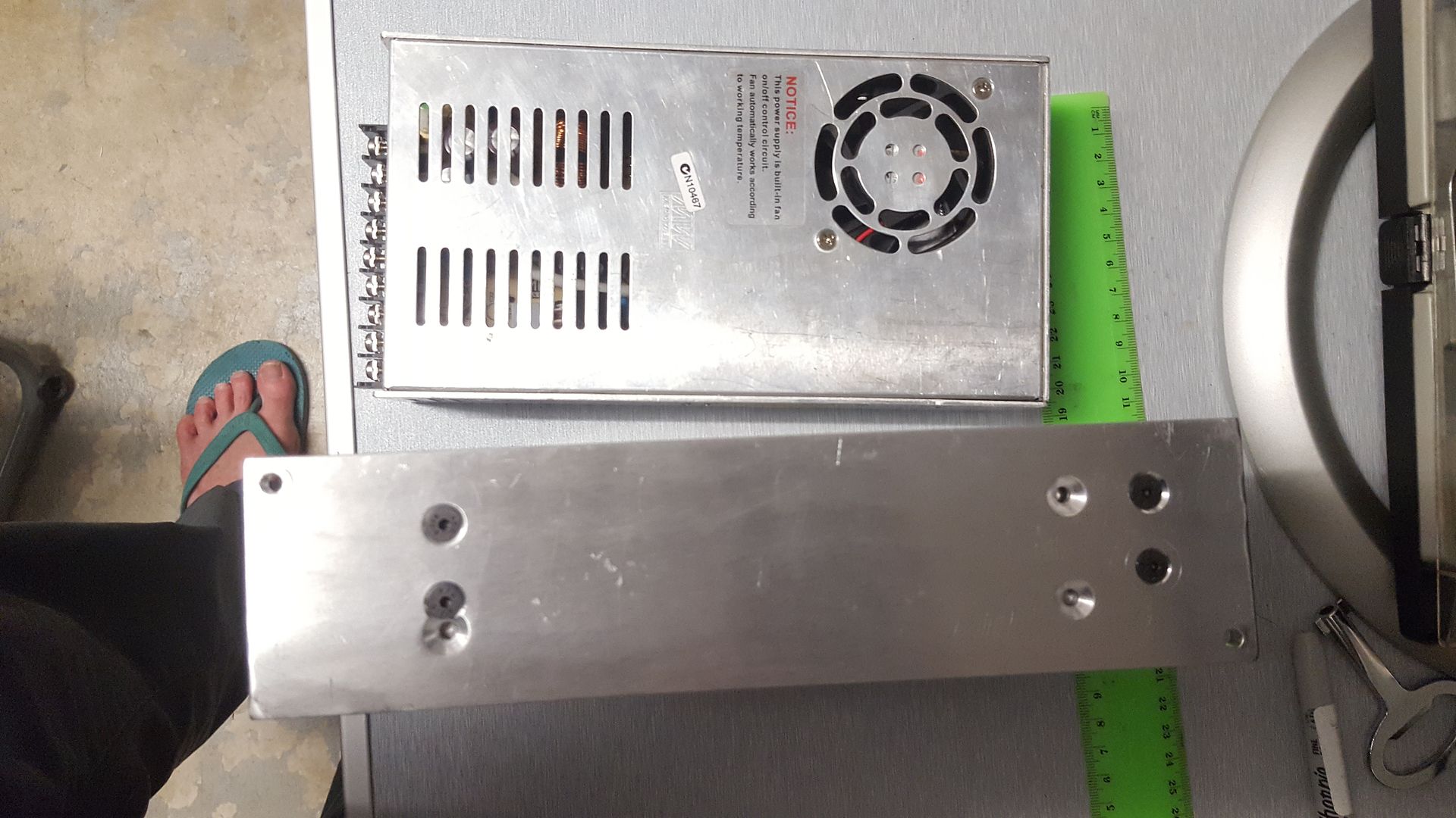
I modified the mount I made from 6mm aluminium so I could bolt the new supply to it. I was able to reuse one hole so it only took a few minutes to revise the original drawing and drill and countersink the holes. The holes will be hidden once installed so it will still look neat.
If I need to, I can DIN rail mount the smaller supply on the enclosure door which will give me 18 amps of power (and maybe a few burnt out AC switches).
I'll have a total draw from steppers of 13.6 amps and I hope that what Gecko say the way steppers work you can draw 40% more power than the power supply rating. I'm going to be drawing 28% more so it sounds OK for now..
One thing I learnt is that if you end up with an 8 wire stepper motor you need to wire them in parallel for a plasma table as you need speed. This means.they will use the most power (4 amps in my case) hence the bigger power supply,. Lucky my stepper drives are good to 4 amps! Hopefully I will have time to refit the new power supply, and rewire the steppers.tomorrow night and get back to business sorting out the Gmoccapy plasma HAL quagmire.
Also steppers online's returns policy means I only have to post the faulty power supply to an Australian address for replacement. They've given me a RO number. It seems it will join the ranks of surplus equipment I've accumulated during this project because a replacement Meanwell power supply arrived from Power Supplies Australia . I've used these guys several times now and they provide really good service.
So here is the working 7.5 amp 48 volt supply I removed on the left beside the newer slimline 10.5 amp one on the right.
I modified the mount I made from 6mm aluminium so I could bolt the new supply to it. I was able to reuse one hole so it only took a few minutes to revise the original drawing and drill and countersink the holes. The holes will be hidden once installed so it will still look neat.
If I need to, I can DIN rail mount the smaller supply on the enclosure door which will give me 18 amps of power (and maybe a few burnt out AC switches).
I'll have a total draw from steppers of 13.6 amps and I hope that what Gecko say the way steppers work you can draw 40% more power than the power supply rating. I'm going to be drawing 28% more so it sounds OK for now..
One thing I learnt is that if you end up with an 8 wire stepper motor you need to wire them in parallel for a plasma table as you need speed. This means.they will use the most power (4 amps in my case) hence the bigger power supply,. Lucky my stepper drives are good to 4 amps! Hopefully I will have time to refit the new power supply, and rewire the steppers.tomorrow night and get back to business sorting out the Gmoccapy plasma HAL quagmire.
Last edit: 18 Jan 2017 12:11 by rodw.
Please Log in or Create an account to join the conversation.
- rodw
-
Topic Author
- Away
- Platinum Member
-
Less
More
- Posts: 12024
- Thank you received: 4100
19 Jan 2017 12:02 - 19 Jan 2017 12:03 #86142
by rodw
Replied by rodw on topic Rods "Spaceship" Scratch built Plasma Cutter build
Well I got my new power supply installed tonight.
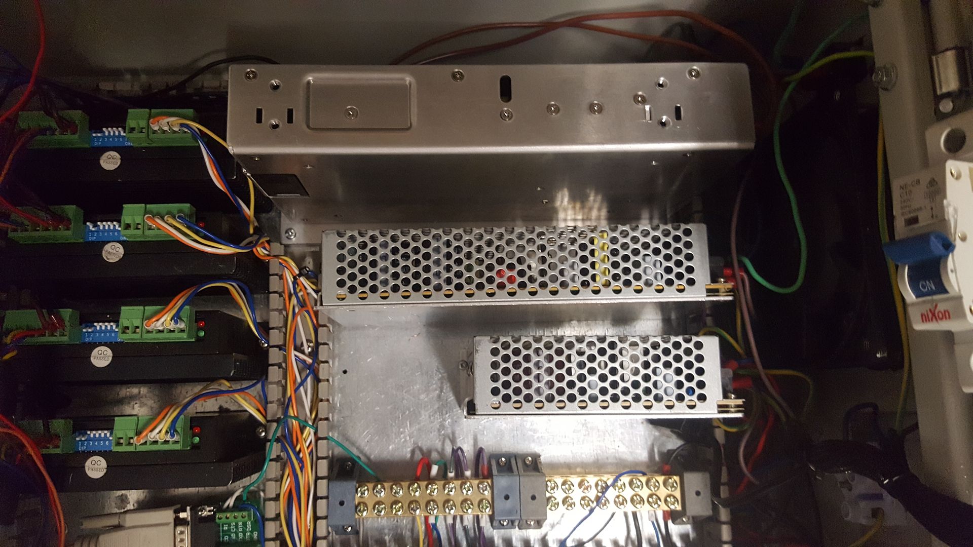
The only problem is the cooling fan blows the wrong way as its against the enclosure fan. Turning it round would mean a fair bit of rewiring on the AC side and also put the AC wiring hard against the 5 volt stepper signals.
When I had problems with the cheap Chinese power supply, I got a 240 volt shock when I was well away from the AC side of the power supply. I'm not sure if I did something stupid (I'm sure I didn't) but I found out why the 48volt circuit LED was not lighting up after this transplant.
The phone photo is not as clear as I'd like but you can see a very scorched current limiting resistor at the bottom of this board.

When I first turned it on with the new power supply, one of the X axis steppers was not working so after swapping wiring around a few times to troubleshoot, I plugged the wires back into the stepper controller the wrong way round and I saw a wisp of smoke coming out of the connector. I figured the stepper driver was already ruined before this happened but to my surprise I went back to the machine half an hour later and the darn thing was working again!
I was thinking I would order another stepper driver so I had something to play with a rotary axis. Why not? I have a rotary table with a NEMA24 attached that drives my Arduino based dividing head controller and there is a spare stepgen on the 7i76e.
I did have one win. Now I have the control box back together, I was able to resolve this bug that was annoying me
forum.linuxcnc.org/gmoccapy/32164-plasma-component-in-gmoccapy
Turns out is was a bug in gmocappy as it was generating typos in the signal names Grrr.
So now, I just have to reconfigure the X axis to use parallel wiring, up the driver current to 4 amps and there is nothing stopping me from finishing off the THC integration into Gmocappy.
The only problem is the cooling fan blows the wrong way as its against the enclosure fan. Turning it round would mean a fair bit of rewiring on the AC side and also put the AC wiring hard against the 5 volt stepper signals.
When I had problems with the cheap Chinese power supply, I got a 240 volt shock when I was well away from the AC side of the power supply. I'm not sure if I did something stupid (I'm sure I didn't) but I found out why the 48volt circuit LED was not lighting up after this transplant.
The phone photo is not as clear as I'd like but you can see a very scorched current limiting resistor at the bottom of this board.
When I first turned it on with the new power supply, one of the X axis steppers was not working so after swapping wiring around a few times to troubleshoot, I plugged the wires back into the stepper controller the wrong way round and I saw a wisp of smoke coming out of the connector. I figured the stepper driver was already ruined before this happened but to my surprise I went back to the machine half an hour later and the darn thing was working again!
I was thinking I would order another stepper driver so I had something to play with a rotary axis. Why not? I have a rotary table with a NEMA24 attached that drives my Arduino based dividing head controller and there is a spare stepgen on the 7i76e.
I did have one win. Now I have the control box back together, I was able to resolve this bug that was annoying me
forum.linuxcnc.org/gmoccapy/32164-plasma-component-in-gmoccapy
Turns out is was a bug in gmocappy as it was generating typos in the signal names Grrr.
So now, I just have to reconfigure the X axis to use parallel wiring, up the driver current to 4 amps and there is nothing stopping me from finishing off the THC integration into Gmocappy.
Last edit: 19 Jan 2017 12:03 by rodw.
Please Log in or Create an account to join the conversation.
Time to create page: 0.186 seconds