Rods "Spaceship" Scratch built Plasma Cutter build
- rodw
-
 Topic Author
- Offline
- Platinum Member
-

Less
More
- Posts: 11960
- Thank you received: 4074
05 Jan 2017 02:14 #85266
by rodw
Darn, I forgot about those. I missed an ideal excuse to buy one of them and I was there today
www.machineryhouse.com.au/T0119
I've always been a bit put off by the magnetic base as msot of my machining is in aluminium. I might change my laser order now.
I do have a good set of Dormer machine taps which have been very useful my cordless drill through this project.
Replied by rodw on topic Rods "Spaceship" Scratch built Plasma Cutter build
For much less than $400 you can buy something like: www.grizzly.com/products/Hand-Tapping-Ma...m_source=grizzly.com and you have a useful tool when you are finished.
Darn, I forgot about those. I missed an ideal excuse to buy one of them and I was there today
www.machineryhouse.com.au/T0119
I've always been a bit put off by the magnetic base as msot of my machining is in aluminium. I might change my laser order now.
I do have a good set of Dormer machine taps which have been very useful my cordless drill through this project.
Please Log in or Create an account to join the conversation.
- rodw
-
Topic Author
- Offline
- Platinum Member
-
Less
More
- Posts: 11960
- Thank you received: 4074
05 Jan 2017 03:37 #85269
by rodw
Replied by rodw on topic Rods "Spaceship" Scratch built Plasma Cutter build
Andy, thanks for your ideas. I got onto my laser cutters and told them not to do the tapping. There are a couple of M4 holes they can't cut 1n 12mm steel but they are going to etch the position for me. I ordered the tapping tool and a Motorguard air filter for the plasma machine.
www.machineryhouse.com.au/C492
But by doing it online (even though they are only 10 minutes from home), they gave me a $50 discount voucher so the savings in laser cutting covered the cost of the parts so the filter was free (apart from my time)!
The M4 holes are for the limit switches at the end of a 1600mm part so I should be able to do them on my mill pretty easily.
Please Log in or Create an account to join the conversation.
- rodw
-
Topic Author
- Offline
- Platinum Member
-
Less
More
- Posts: 11960
- Thank you received: 4074
05 Jan 2017 11:23 #85278
by rodw
Replied by rodw on topic Rods "Spaceship" Scratch built Plasma Cutter build
Well, I made 3 trips to Machinery House today. One to buy a bandsaw blade for work, then back to pick it up from their warehouse across the road from the showroom becasue my desire for coffee resulted in temporary amnesia and the third to collect the tool that Andy suggested I get that I had bought online. Of course they waited until I got home before they sent me an email telling me it was ready for collection!
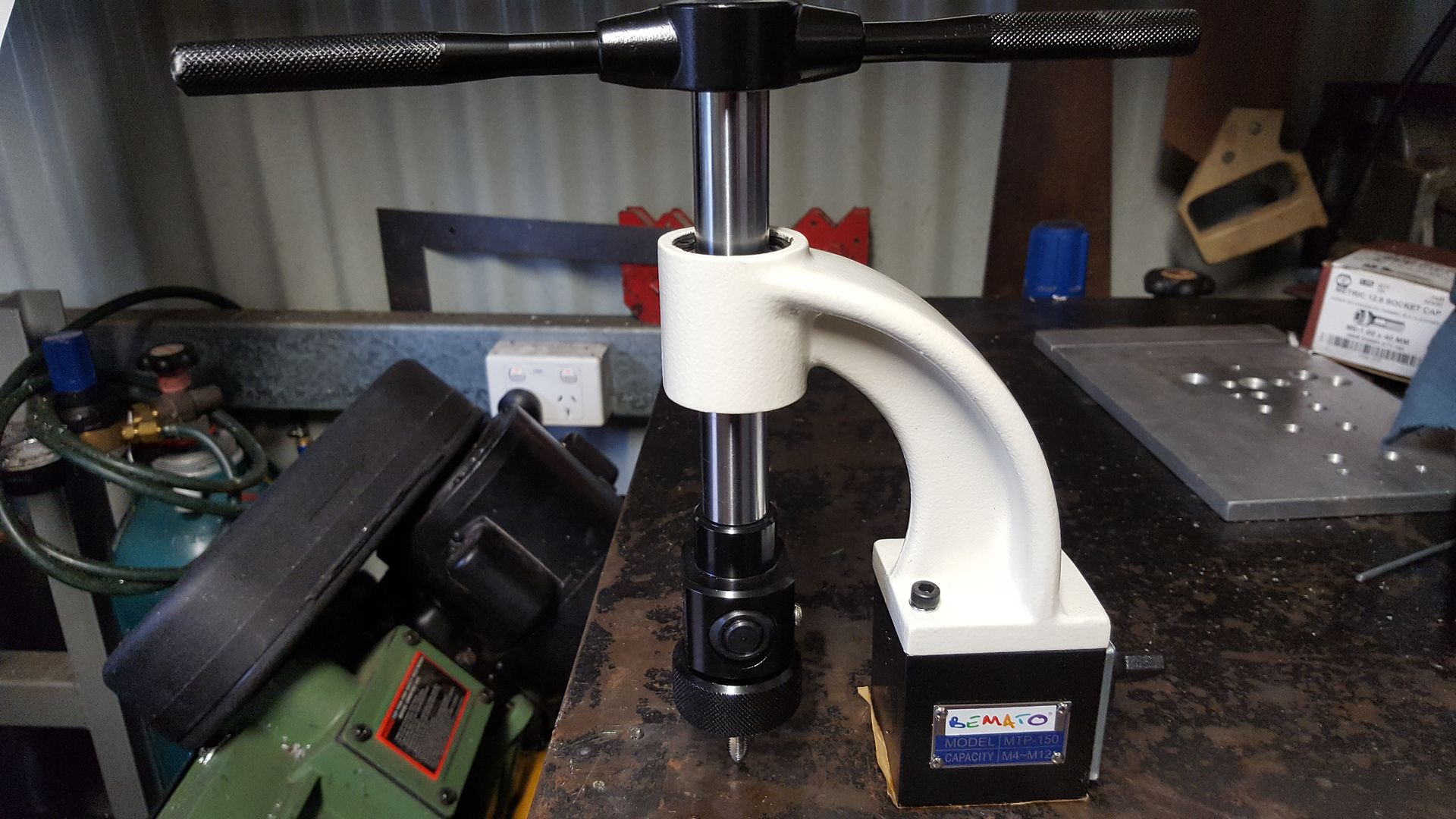
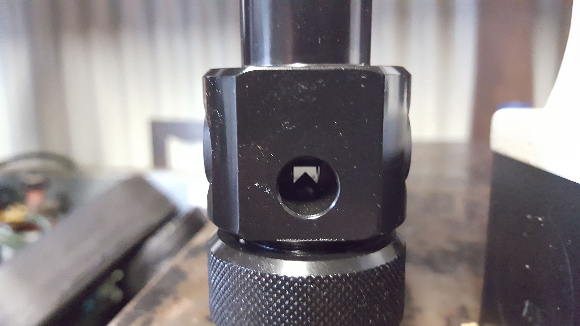
It says it goes from M4 to M12. Most of the holes I need to tap are M6 and the tap is buried pretty deep once installed
I also picked up a filter for the plasma air supply.
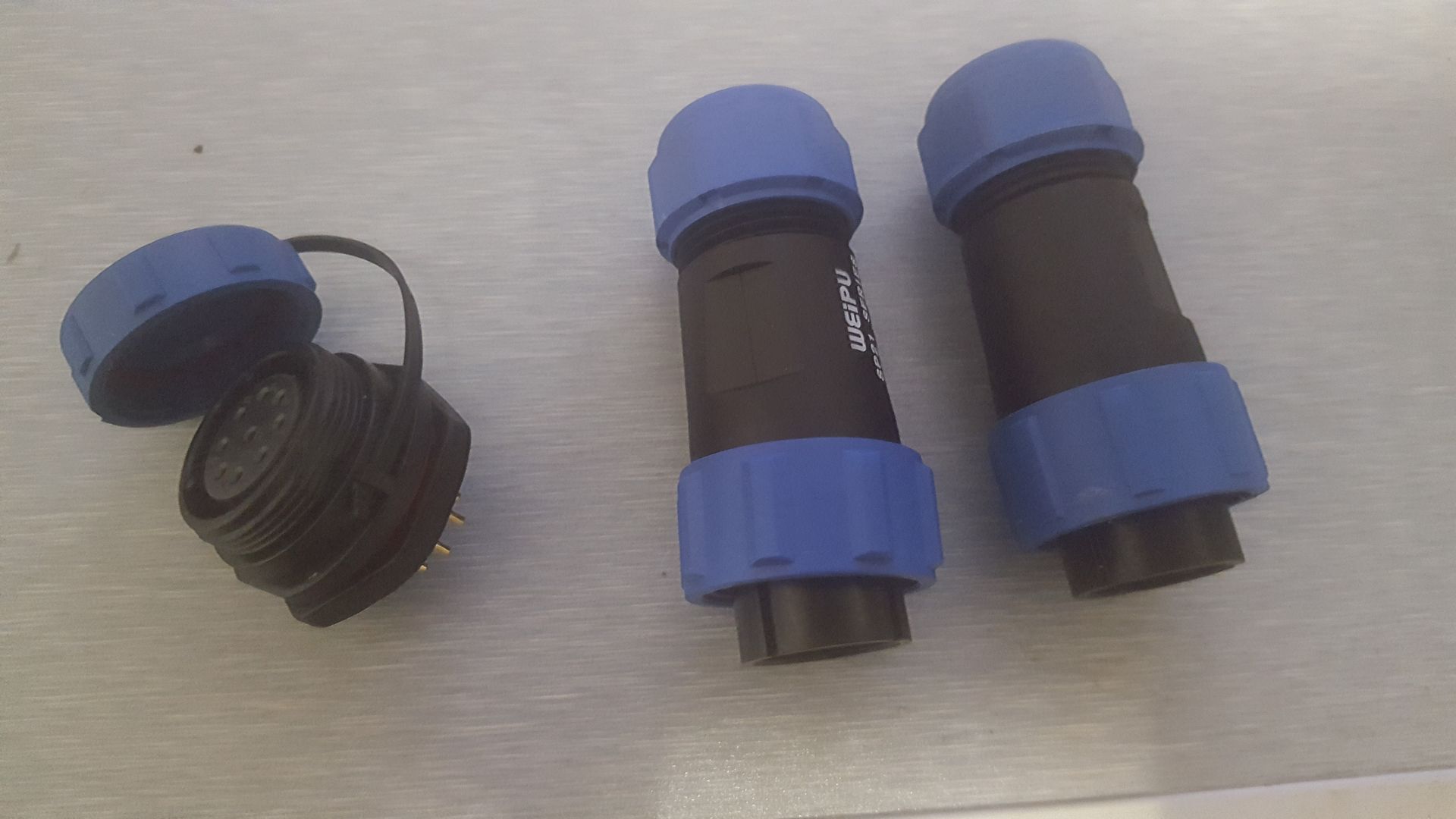
When I got home, I found that the slow boat from China had arrived while I was away and the connector for the plasma cutter cable at the control box end had arrived.
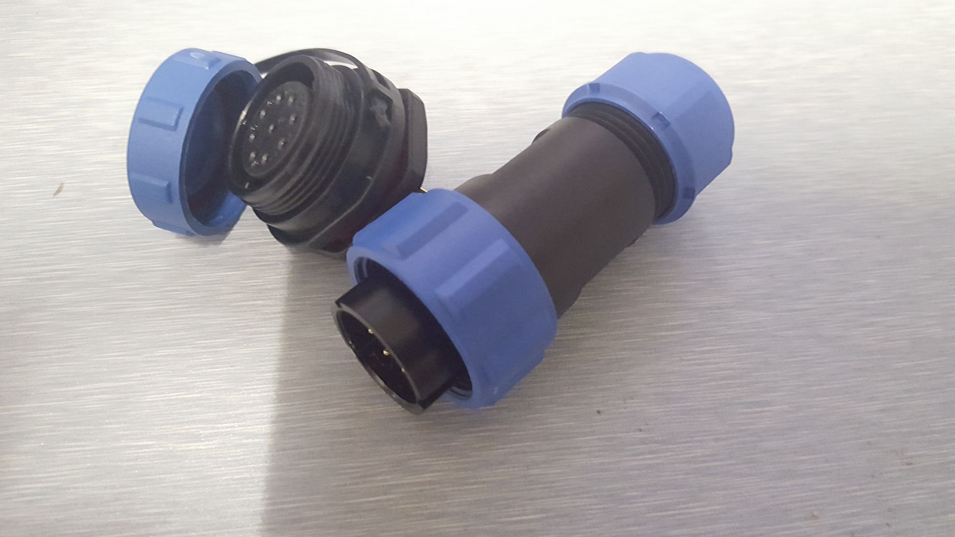
Its a pretty good match for the one that came with my plasma cutter shown on the right.
Drat, hit, the dreaded link limit again. to be continued...
It says it goes from M4 to M12. Most of the holes I need to tap are M6 and the tap is buried pretty deep once installed
I also picked up a filter for the plasma air supply.
When I got home, I found that the slow boat from China had arrived while I was away and the connector for the plasma cutter cable at the control box end had arrived.
Its a pretty good match for the one that came with my plasma cutter shown on the right.
Drat, hit, the dreaded link limit again. to be continued...
Please Log in or Create an account to join the conversation.
- rodw
-
Topic Author
- Offline
- Platinum Member
-
Less
More
- Posts: 11960
- Thank you received: 4074
05 Jan 2017 11:23 - 05 Jan 2017 21:10 #85279
by rodw
Replied by rodw on topic Rods "Spaceship" Scratch built Plasma Cutter build
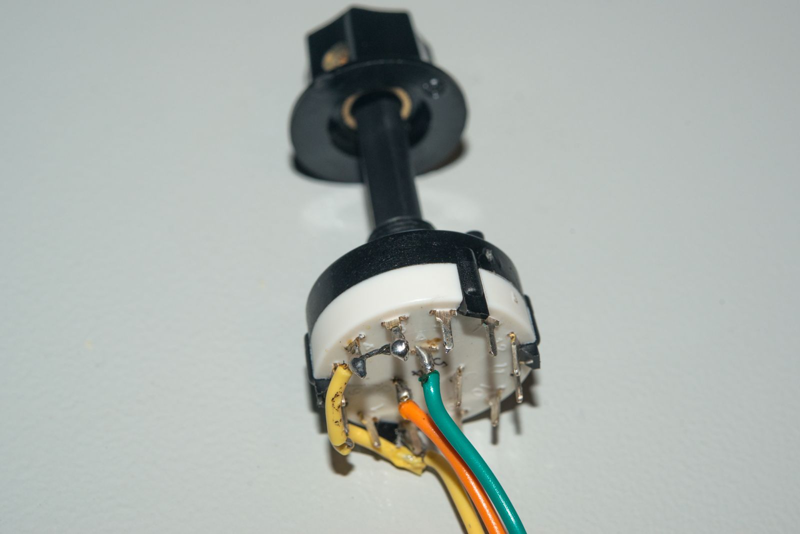
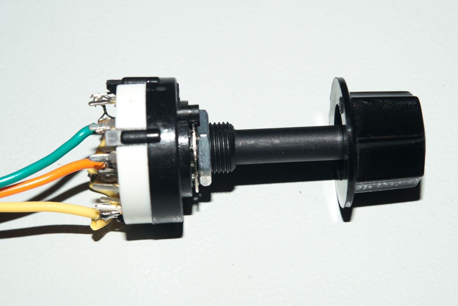
But back onto LinuxCNC, I promised I'd show document how I got an MPG running on the 7i76e. Lets start with the scale selector. I knew I need a 2 bit binary output but I've only ever made them in software before so I asked a friend what to get and he said to get one of
these from Jaycar
. That looked right to me so I grabbed one as I was close to one of their shops.
There were 3 outputs in the centre of the switch (A, B & C). We only need two of these so I picked A & B. But it really did my head in trying to work out how to use it in the absence of documentation. After a while with a multimeter I worked out which wire went where but I still could not work it out. Then I decided I needed to build a truth table showing the binary logic required:
And work out what wires were required to be live where ever there was a 1. My switch pinout said I needed to make pins 3, 4, 6 and 8 live so I tied them together with a yellow wire attached to +24v and an orange and green wire on the centre inputs going to the mux4 pins.
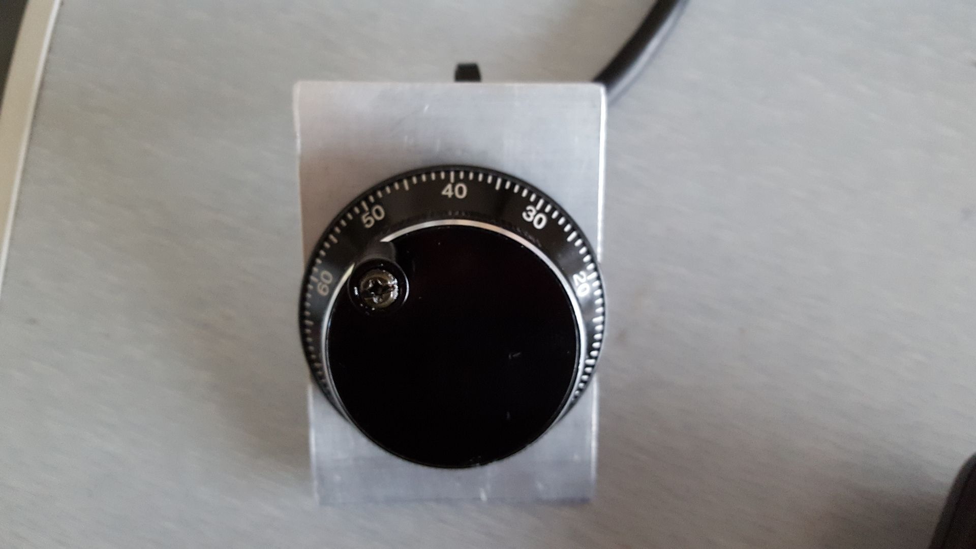
I made a bracket for the 100PPR encoder wheel from some scrap angle iron so it would not short out
The wiring was pretty simple
I stole some 5 volt power from one of the stepper power pins.
Encode A connects to TB3.16
Encoder B connects to TB3.17
I did run into trouble until I found a post from PCW which said if you are using a separate 5V power supply like I am, you needed to tie the 24 volt and 5 volt pin Grounds together. Eg. Connect TB1.1 to TB2.23. But if you follow this wiring schematic , you won't need to do this
As the 7i76e has 2 encoder inputs, I figured I'd use separate encoders for the X & Y axis.
Some of the examples I had seen used the -not signal from an unused input for the encoder enable inut but this looked a bit dodgy to me. Why not simply OR the 2 encoder input pins together and use the output from that as the enable signal? By doing that , the encode will be disabled when the scale switch is at position 0 and enabled at any of the scale settings. Nice and clean!
Here is what the HAL file looks like:
This is set up for a metric machine and the scale is 1mm, 0.1mm and 0.01mm. If you find the scale is reversed, it is becasue the pins are mapped in the reverse order. (eg low order pin connected to high order bit). If this happens to you, just edit the pins in this code.
Remember to change this line based on your config. I had already used a few or2'sWell, thats about it for now. The shopping list is becoming very short.
1. 9 core shielded wire for the connection to the plasma power supply now the connector is to hand
2. A 3 stage air filter including a desiccant drier stage I've had my eye on.
3. About 10 metres of 100 x 100 x 5mm SHS for the frame and some other sundry steel.
The main things I have to do in HAL are:
1. All the THC stuff
2. Sort out my stepper drives so they are working on the correct axis
3. Implement Gantry Joint Axis .
4. Get my warning lights working the way I want them to and I'll need some help on that one.
There were 3 outputs in the centre of the switch (A, B & C). We only need two of these so I picked A & B. But it really did my head in trying to work out how to use it in the absence of documentation. After a while with a multimeter I worked out which wire went where but I still could not work it out. Then I decided I needed to build a truth table showing the binary logic required:
 Pos   A B
  0:   0 0
  1:   0 1
  2:   1 0
  3:   1 1
And work out what wires were required to be live where ever there was a 1. My switch pinout said I needed to make pins 3, 4, 6 and 8 live so I tied them together with a yellow wire attached to +24v and an orange and green wire on the centre inputs going to the mux4 pins.
I made a bracket for the 100PPR encoder wheel from some scrap angle iron so it would not short out
The wiring was pretty simple
I stole some 5 volt power from one of the stepper power pins.
Encode A connects to TB3.16
Encoder B connects to TB3.17
I did run into trouble until I found a post from PCW which said if you are using a separate 5V power supply like I am, you needed to tie the 24 volt and 5 volt pin Grounds together. Eg. Connect TB1.1 to TB2.23. But if you follow this wiring schematic , you won't need to do this
As the 7i76e has 2 encoder inputs, I figured I'd use separate encoders for the X & Y axis.
Some of the examples I had seen used the -not signal from an unused input for the encoder enable inut but this looked a bit dodgy to me. Why not simply OR the 2 encoder input pins together and use the output from that as the enable signal? By doing that , the encode will be disabled when the scale switch is at position 0 and enabled at any of the scale settings. Nice and clean!
Here is what the HAL file looks like:
# Metric units used
loadrt hm2_eth board_ip="10.10.10.10" config="firmware=hm2/7i76/7i76e.BIT num_encoders=1 num_pwmgens=0 num_stepgens=5  sserial_port_0=2xxxx"

loadrt mux4 count=1
addf mux4.0 servo-thread
loadrt or2 count=4
addf or2.3  servo-thread

setp axis.x.jog-vel-mode 0
net x-jog-counter <=  hm2_7i76e.0.7i76.0.0.enc0.count
net x-jog-counter => axis.x.jog-counts
net mux-in1 or2.3.in0 <= hm2_7i76e.0.7i76.0.0.input-22 => mux4.0.sel0
net mux-in2 or2.3.in1 <= hm2_7i76e.0.7i76.0.0.input-21 => mux4.0.sel1
net x-jog-enable <= or2.3.out
net x-jog-enable => axis.x.jog-enable
setp mux4.0.in0 0.0
setp mux4.0.in1 1.0
setp mux4.0.in2 0.1
setp mux4.0.in3 0.01
net x-jog-scale mux4.0.out => axis.x.jog-scale
This is set up for a metric machine and the scale is 1mm, 0.1mm and 0.01mm. If you find the scale is reversed, it is becasue the pins are mapped in the reverse order. (eg low order pin connected to high order bit). If this happens to you, just edit the pins in this code.
net mux-in1 or2.3.in0 <= hm2_7i76e.0.7i76.0.0.input-22 => mux4.0.sel0
net mux-in2 or2.3.in1 <= hm2_7i76e.0.7i76.0.0.input-21 => mux4.0.sel1
Remember to change this line based on your config. I had already used a few or2's
loadrt or2 count=41. 9 core shielded wire for the connection to the plasma power supply now the connector is to hand
2. A 3 stage air filter including a desiccant drier stage I've had my eye on.
3. About 10 metres of 100 x 100 x 5mm SHS for the frame and some other sundry steel.
The main things I have to do in HAL are:
1. All the THC stuff
2. Sort out my stepper drives so they are working on the correct axis
3. Implement Gantry Joint Axis .
4. Get my warning lights working the way I want them to and I'll need some help on that one.
Last edit: 05 Jan 2017 21:10 by rodw.
The following user(s) said Thank You: snoozer77, Haarie, my1987toyota
Please Log in or Create an account to join the conversation.
- rodw
-
Topic Author
- Offline
- Platinum Member
-
Less
More
- Posts: 11960
- Thank you received: 4074
05 Jan 2017 21:32 #85305
by rodw
Replied by rodw on topic Rods "Spaceship" Scratch built Plasma Cutter build
Well, it seems people are following along. I had a request overnight to explains some of my HAL code. It just goes to show once you understand something, you gloss over the detail where the hard bits live. This was not meant to be a tutorial, but for the other beginners like me here goes:
You should know by now that loadrt loads a HAL module into your setup
Once you load a module, you usually need to put it in the thread you want to use it in with addf
So you usually need a loadrt and an addf statement before you can use it.
Some HAL modules need you to set a parameter to a given value. you use setp to do that.
With some modules (like or.2), you may use them in multiple places so you need to add a count parameter. I've already got 3 or2 statements in use so I added one more here
Real computers count starting from 0. Just ask any assembly language or C programmer. Once you start counting from 0, a lot of things become a lot easier. So HAL numbers each of the statements as or2.0, or2.1, or2.2, or2.3. As this is the 4th or i've added, I am using or2.3.
But more importantly, because I am using a 7i76e, I need to load the mesa driver hm2_eth.
pncconf makes a valiant effort at making this statement but you probably need to tell it the ip address its installed on. If you read the documentation, you need to place the driver in mode 2. This is the bit that does that sserial_port_0=2xxxx. I found this example on the forum here so I copied it. Don't ask me what the other statements do.")
I'm using master branch to get the gantry joint axis feature and I think this has meant some code has changed as the axis module now has axis.x, axis.y etc instead of axis.0, axis.1 etc. So lets look at the next snippet which just sets up some defaults.
The jog-vel-mode parameter can be either 0 or 1. I've set it to 0 so that a given jog step completes. Using a 1 here means that motion stops as soon as you stop turning the wheel.
The next 2 lines read the 7i76e enc0.count and sends it to axis X so that HAL knows which axis to move. You can fold this up onto one line but I broke it up for ease of reading (so try to do this yourself as a training exercise. I did.)
So lets deal with the scale selection. To conserve pins most examples use the mux4 hal component and I realised I left these lines out of my example to load it (now corrected)
This conserves pins once you can work out how to wire in a binary coded switch
these next lines do 3 things. They load the value of the input pins (I'm using 21 & 22) used by the selector switch into a variable I created but along the way, it also loads the value of these pins into an or2 statement. They also send the pin values to our mux4 component inputs.
I think you could break these up onto more lines to make it easier to read so try doing that as a learning exercise.
Before an axis can be jogged, it needs to be enabled using x-jog-enable and that is the purpose of my or.2 output. It will be true (1) whenever a scale is selected with the switch and 0 when the switch is in the off position
Now we need to set the scale according to the position table I documented in the previous post using setp.
You will need to alter the scale values if your machine is using inches.
And now finally tell axis.x which scale to use
So there you have it. A working single axis MPG handwheel using the Mesa ENC0 input and a scale selector switch.
I think Andy said somewhere once that this stuff is hard becasue it really is hard but I hope that this explains whats going on.
You should know by now that loadrt loads a HAL module into your setup
Once you load a module, you usually need to put it in the thread you want to use it in with addf
So you usually need a loadrt and an addf statement before you can use it.
Some HAL modules need you to set a parameter to a given value. you use setp to do that.
With some modules (like or.2), you may use them in multiple places so you need to add a count parameter. I've already got 3 or2 statements in use so I added one more here
loadrt or2 count=4But more importantly, because I am using a 7i76e, I need to load the mesa driver hm2_eth.
loadrt hm2_eth board_ip="10.10.10.10" config="firmware=hm2/7i76/7i76e.BIT num_encoders=1 num_pwmgens=0 num_stepgens=5 sserial_port_0=2xxxx" pncconf makes a valiant effort at making this statement but you probably need to tell it the ip address its installed on. If you read the documentation, you need to place the driver in mode 2. This is the bit that does that sserial_port_0=2xxxx. I found this example on the forum here so I copied it. Don't ask me what the other statements do.
I'm using master branch to get the gantry joint axis feature and I think this has meant some code has changed as the axis module now has axis.x, axis.y etc instead of axis.0, axis.1 etc. So lets look at the next snippet which just sets up some defaults.
setp axis.x.jog-vel-mode 0
net x-jog-counter <=  hm2_7i76e.0.7i76.0.0.enc0.count
net x-jog-counter => axis.x.jog-counts
The jog-vel-mode parameter can be either 0 or 1. I've set it to 0 so that a given jog step completes. Using a 1 here means that motion stops as soon as you stop turning the wheel.
The next 2 lines read the 7i76e enc0.count and sends it to axis X so that HAL knows which axis to move. You can fold this up onto one line but I broke it up for ease of reading (so try to do this yourself as a training exercise. I did.)
So lets deal with the scale selection. To conserve pins most examples use the mux4 hal component and I realised I left these lines out of my example to load it (now corrected)
loadrt mux4 count=1
addf mux4.0 servo-thread
This conserves pins once you can work out how to wire in a binary coded switch
these next lines do 3 things. They load the value of the input pins (I'm using 21 & 22) used by the selector switch into a variable I created but along the way, it also loads the value of these pins into an or2 statement. They also send the pin values to our mux4 component inputs.
net mux-in1 or2.3.in0 <= hm2_7i76e.0.7i76.0.0.input-22 => mux4.0.sel0
net mux-in2 or2.3.in1 <= hm2_7i76e.0.7i76.0.0.input-21 => mux4.0.sel1
I think you could break these up onto more lines to make it easier to read so try doing that as a learning exercise.
Before an axis can be jogged, it needs to be enabled using x-jog-enable and that is the purpose of my or.2 output. It will be true (1) whenever a scale is selected with the switch and 0 when the switch is in the off position
net x-jog-enable <= or2.3.out
net x-jog-enable => axis.x.jog-enable
Now we need to set the scale according to the position table I documented in the previous post using setp.
# jog scale for each switch position in mm
setp mux4.0.in0 0.0
setp mux4.0.in1 1.0
setp mux4.0.in2 0.1
setp mux4.0.in3 0.01And now finally tell axis.x which scale to use
net x-jog-scale mux4.0.out => axis.x.jog-scaleSo there you have it. A working single axis MPG handwheel using the Mesa ENC0 input and a scale selector switch.
I think Andy said somewhere once that this stuff is hard becasue it really is hard but I hope that this explains whats going on.
The following user(s) said Thank You: Clive S, gerold, Masiwood123
Please Log in or Create an account to join the conversation.
- rodw
-
Topic Author
- Offline
- Platinum Member
-
Less
More
- Posts: 11960
- Thank you received: 4074
07 Jan 2017 00:44 - 07 Jan 2017 00:47 #85378
by rodw
Replied by rodw on topic Rods "Spaceship" Scratch built Plasma Cutter build
One of the things I wanted to do is to get some warning lights enabled as a traffic light system. After a fruitless afternoon yesterday, Todd wrote the code out for me on this thread
forum.linuxcnc.org/24-hal-components/321...green?start=10#85375
Of course, it is never as simple as it seems to implement a code example in Hal.
This is what Todd gave me
And becasue I wanted to also keep the functionality of the run/step hold/resume buttons from this example
forum.linuxcnc.org/47-hal-examples/13201...-hold-resume-buttons
This is what I came up with
And here it is in action
Ultimately, I had in mind to add a stack light on top of the gantry so the machine status can be seen at a glance across the room. Something like this one (when I can find one with LED's in it/

www.ebay.com.au/itm/DC-24V-3-Bulbs-Red-G...2:g:lMQAAOSw8w1YAqxg
forum.linuxcnc.org/24-hal-components/321...green?start=10#85375
Of course, it is never as simple as it seems to implement a code example in Hal.
This is what Todd gave me
loadrt and2 count=2
loadrt xor2 count=1
loadrt siggen num_chan=1
addf and2.0 servo-thread
addf and2.1 servo-thread
addf xor2.0 servo-thread
addf siggen.0.update servo-thread

setp siggen.0.frequency 2

#Yellow Light
net yellow-in1 <= halui.machine.is-on => and2.0.in0
net yellow-in2 <= halui.program.is-idle => and2.0.in1
net yellow-out <= and2.0.out
net yellow-out => hm2_7i76e.0.7i76.0.0.output-01

#Green Light
net green-in1 <= halui.program.is-running => xor2.0.in0
net green-in2 <= halui.program.is-paused => and2.1.in1
net flash <= siggen.0.clock => and2.1.in0
net green-flash <= and2.1.out => xor2.0.in1
net green-on <= xor2.0.out => hm2_7i76e.0.7i76.0.0.output-02

#Red Light
net red-on <= halui.estop.is-activated => hm2_7i76e.0.7i76.0.0.output-00
And becasue I wanted to also keep the functionality of the run/step hold/resume buttons from this example
forum.linuxcnc.org/47-hal-examples/13201...-hold-resume-buttons
This is what I came up with
loadrt xor2 count=1
loadrt siggen num_chan=1
loadrt and2 count=6

addf and2.0                   servo-thread
addf and2.1                   servo-thread
addf and2.2                   servo-thread
addf and2.3                   servo-thread
addf and2.4                   servo-thread
addf and2.5                   servo-thread
addf xor2.0                    servo-thread

# External Program Pause/Resume and Run/Step Buttons
# Pause/Resume Section
net pause-resume-btn and2.0.in0 and2.1.in0 <= hm2_7i76e.0.7i76.0.0.input-02-not
net pause-on toggle2nist.0.is-on <= and2.0.in1 <= and2.3.in1 <= and2.5.in1 <= halui.program.is-paused
net run-on and2.1.in1 <= xor2.0.in0 <= halui.program.is-running
net pause-sig or2.0.in0 <= and2.0.out
net resume-sig or2.0.in1 <= and2.1.out
net toggle-ok toggle.0.in <= or2.0.out
net togglesig toggle2nist.0.in <= toggle.0.out
net toggleon halui.program.pause <= toggle2nist.0.on
net toggleoff halui.program.resume <= toggle2nist.0.off
# Run/Step Section
net run-step-btn and2.2.in0 and2.3.in0 <= hm2_7i76e.0.7i76.0.0.input-01
net idle-on and2.2.in1 <= and2.4.in1 <= halui.program.is-idle
# net pause.on and2.3.in1 <= halui.program.is-paused
# and2.3.in1 was added in the net pause-on statement in Pause/Resume Section
net run-sig halui.mode.auto halui.program.run <= and2.2.out
net step-sig halui.program.step <= and2.3.out

net estop-out estop-latch.0.fault-out

# --- RED, GREEN AMBER WARNING LIGHTS ---

#Yellow Light
net yellow-in1 <= halui.machine.is-on => and2.4.in0
net idle-on <= halui.program.is-idle => and2.4.in1
net yellow-out <= and2.4.out
net yellow-out => hm2_7i76e.0.7i76.0.0.output-01

#Green Light

net flash <= siggen.0.clock => and2.5.in0
net green-flash <= and2.5.out => xor2.0.in1
net green-on <= xor2.0.out => hm2_7i76e.0.7i76.0.0.output-02

#Red Light
net estop-out hm2_7i76e.0.7i76.0.0.output-00
And here it is in action
Ultimately, I had in mind to add a stack light on top of the gantry so the machine status can be seen at a glance across the room. Something like this one (when I can find one with LED's in it/
www.ebay.com.au/itm/DC-24V-3-Bulbs-Red-G...2:g:lMQAAOSw8w1YAqxg
Last edit: 07 Jan 2017 00:47 by rodw.
The following user(s) said Thank You: snoozer77, hairy
Please Log in or Create an account to join the conversation.
- Clive S
- Offline
- Platinum Member
-
Less
More
- Posts: 2204
- Thank you received: 486
07 Jan 2017 10:30 #85391
by Clive S
Replied by Clive S on topic Rods "Spaceship" Scratch built Plasma Cutter build
Rod
This looks like it has LEDs in it according the the tittle. www.aliexpress.com/item/24V-Industrial-R...0010508.4.119.OZ1S8p
This looks like it has LEDs in it according the the tittle. www.aliexpress.com/item/24V-Industrial-R...0010508.4.119.OZ1S8p
Please Log in or Create an account to join the conversation.
- rodw
-
Topic Author
- Offline
- Platinum Member
-
Less
More
- Posts: 11960
- Thank you received: 4074
07 Jan 2017 11:34 #85394
by rodw
Replied by rodw on topic Rods "Spaceship" Scratch built Plasma Cutter build
Thanks Clive. There seems to be a few around on eBay as well. I even found one on Aliexpress for $10 with free freight even.Rod
This looks like it has LEDs in it according the the tittle. www.aliexpress.com/item/24V-Industrial-R...0010508.4.119.OZ1S8p
Please Log in or Create an account to join the conversation.
- rodw
-
Topic Author
- Offline
- Platinum Member
-
Less
More
- Posts: 11960
- Thank you received: 4074
08 Jan 2017 04:03 #85451
by rodw
Replied by rodw on topic Rods "Spaceship" Scratch built Plasma Cutter build
I ended up ordering this Stack light
www.aliexpress.com/snapshot/0.html?order...roductId=32718843984
The same seller had one without the mast extension for $10 but I thought the mast extension might be handy.
Anyway, I've finally set up my THC component so its fully functional in bench testing. I had some trouble becasue I forgot that I'd set the frequency on the THCAD board to 1/32. Eventually I remembered and once I reworked it, it is spot on accurate.
I added a 24 volt LED light to the Spindle output relay and tested it went on with gcode M3 and off with M4
I added a switch to the THC ArcOk input pin to +24v so I could test it
I grabbed a 100k potentiometer and took a +5v wire from one of the 7i76e stepper drivers and ran it though the pot to the IN+ input on the thcad. I ran a ground wire from the stepper -5v to the IN- port on the THCAD.. Turning the pot varied the voltage from about 2.5v to 5v.
Then I just used Hal configuration window in axis to check the thc pins to make sure that they were doing the right thing. thc.volts at the console tracked the mutimeter on the THCAD IN terminals nicely.
Here is the HAL setup
The last 2 lines were just to test that the signal was being enabled and just uses a spare input pin that has a TRUE output.
The maths in the comments is pretty self explanatory. I referenced these 2 links to build this config
The THC manual page linuxcnc.org/docs/html/man/man9/thc.9.html
Big John's Hal example gnipsel.com/shop/plasma/files/plasma.hal
I decided to start from the manual page to see how well I understood hal and basically used Johns to check my input at the end.
I'm pretty sure PCW said it was best to use the THCAD 1/32 frequency divider. If anybody thinks I should do otherwise, please let me know.
www.aliexpress.com/snapshot/0.html?order...roductId=32718843984
The same seller had one without the mast extension for $10 but I thought the mast extension might be handy.
Anyway, I've finally set up my THC component so its fully functional in bench testing. I had some trouble becasue I forgot that I'd set the frequency on the THCAD board to 1/32. Eventually I remembered and once I reworked it, it is spot on accurate.
I added a 24 volt LED light to the Spindle output relay and tested it went on with gcode M3 and off with M4
I added a switch to the THC ArcOk input pin to +24v so I could test it
I grabbed a 100k potentiometer and took a +5v wire from one of the 7i76e stepper drivers and ran it though the pot to the IN+ input on the thcad. I ran a ground wire from the stepper -5v to the IN- port on the THCAD.. Turning the pot varied the voltage from about 2.5v to 5v.
Then I just used Hal configuration window in axis to check the thc pins to make sure that they were doing the right thing. thc.volts at the console tracked the mutimeter on the THCAD IN terminals nicely.
Here is the HAL setup
# --- TURN TORCH ON  ---
net spindle-on motion.spindle-on => hm2_7i76e.0.7i76.0.0.output-04

# --- TOUCH OFF ---
net torch-probe motion.probe-input <= hm2_7i76e.0.7i76.0.0.input-09-not

# --- THC - TORCH HEIGHT CONTROLLER ---
# thc calibration data 0v = 122.9 kHz (122900), 10v = 925.7 kHz (925700)
# so at 10V, 925700 = 122900 + (80280 * 10)
# but we are using 1/32 divider on THC board
# 1/32 input 0v = 3840.625, 10v = 28928.125
# 1/32 at 10v 28928.125 = 3840.625 + 2508.75 * 10
# 1/32 scale = 1/2508.75 = 0.000398605

setp thc.vel-scale 0.000398605
setp thc.scale-offset 3840.625

setp thc.velocity-tol 1.0
setp thc.voltage-tol  1.0
#This might need to be increased
setp thc.correction-vel 0.00001
setp hm2_7i76e.0.encoder.00.scale -1
setp hm2_7i76e.0.encoder.00.counter-mode 1

net thc-encoder-vel hm2_7i76e.0.encoder.00.velocity => thc.encoder-vel
net thc-current-vel thc.current-vel      <= motion.current-vel
net thc-requested-vel thc.requested-vel    <= motion.requested-vel
net spindle-on => thc.torch-on
# starts the motion when the plasma arc has transfered to the work
net start-motion-input thc.arc-ok <= motion.digital-in-00  <= hm2_7i76e.0.7i76.0.0.input-10

#enable THC just for TESTING
net thc-enable thc.enable <= hm2_7i76e.0.7i76.0.0.input-31-not
The last 2 lines were just to test that the signal was being enabled and just uses a spare input pin that has a TRUE output.
The maths in the comments is pretty self explanatory. I referenced these 2 links to build this config
The THC manual page linuxcnc.org/docs/html/man/man9/thc.9.html
Big John's Hal example gnipsel.com/shop/plasma/files/plasma.hal
I decided to start from the manual page to see how well I understood hal and basically used Johns to check my input at the end.
I'm pretty sure PCW said it was best to use the THCAD 1/32 frequency divider. If anybody thinks I should do otherwise, please let me know.
Please Log in or Create an account to join the conversation.
- rodw
-
Topic Author
- Offline
- Platinum Member
-
Less
More
- Posts: 11960
- Thank you received: 4074
09 Jan 2017 13:36 #85515
by rodw
Replied by rodw on topic Rods "Spaceship" Scratch built Plasma Cutter build
Well, I'm a bit stumped here tonight and its late (well not by Tommy's standards) so I'm going to sleep on it. Because I've only got a gantry (Y & Z), I did not have the stepper motors on the right stepgens and tonight I decided to see if I could fix it and start to set up for Joint Axis on the X axis as it won't be long before I have all axes working.. I plugged the steppers into their correct controllers. I swapped the X axis over to the Y axis in the hal and ini files and its working perfectly. I had the machine configured as XYZ and now I'e set it up as a XXYZ with the axies in bold being the ones I've got active now (except the Z is not working)
The Z on the other hand is not behaving. When jogging, it issues a very faint click and a tiny bit of movement (that you can feel but can't really see the movement. I wondered if I had the limit switches misconfigured and it was sitting on a limit switch but this is not the case and they check out OK. They trigger an error correctly.
I'll double check the wiring in the morning in case I got that wrong between the 7i76e and the stepper controller. I moved all of the signals in HAL and INI files from Joint 1 to Joint 3. I've previously checked the stepper driver is OK.
I'm sure I'll get to the bottom of it but if anyone has some ideas on where to look, please let me know.
Please Log in or Create an account to join the conversation.
Time to create page: 0.628 seconds