Rods "Spaceship" Scratch built Plasma Cutter build
- islander261
- Offline
- Platinum Member
-

Less
More
- Posts: 757
- Thank you received: 216
23 Jan 2019 16:11 - 23 Jan 2019 17:01 #124673
by islander261
Replied by islander261 on topic Rods "Spaceship" Scratch built Plasma Cutter build
Rod
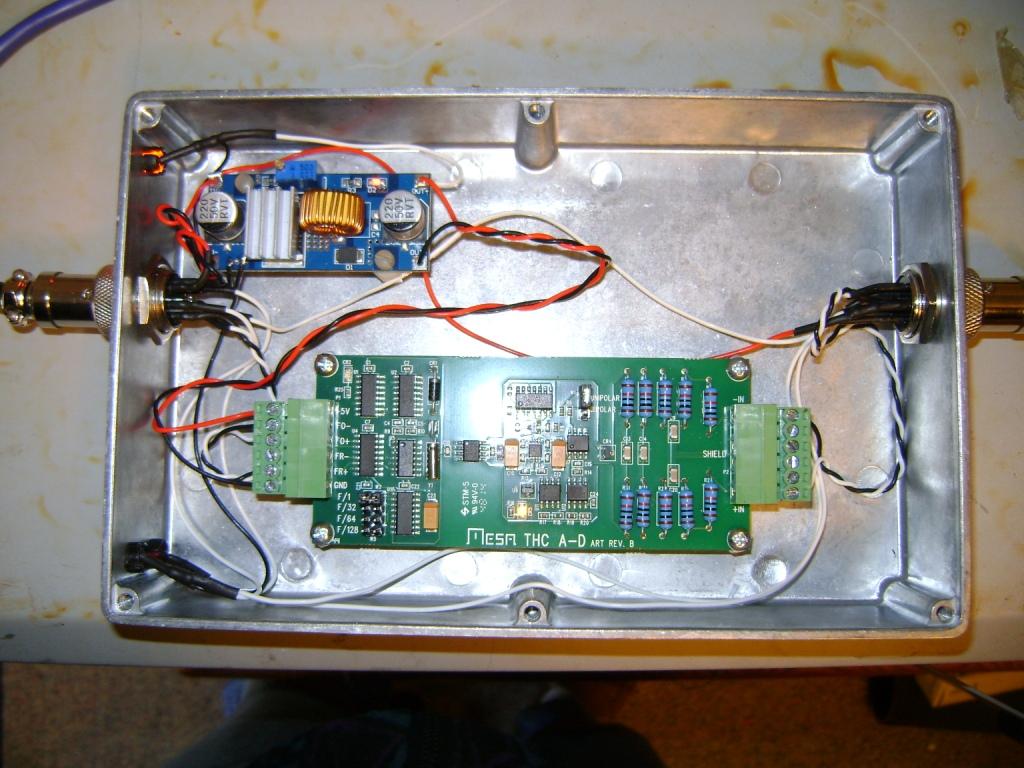
My A60 doesn't have the factory divider so the I mounted my DIY voltage divider there. My THCad is mounted in a shielded box that is either on top or under my A60 and connects to the rest of my controls through a shielded Ethernet cable with Chinese circular connectors.
What I have for ohmic sensing. I have an isolated power supply (wall wart) that only powers the ohmic sensing. The power supply is protected with 1N4007 diodes so the arc voltage can't get there. I have a DPST relay to switch both sides of the circuit to disconnect it from the work and the torch shield when I am not actually measuring. I then use an Opto22 dc input module to sense when the circuit is complete. Every thing is series connected. Now with all that if you aren't going to cut sheet thinner than about 5mm you will have no need for ohmic sensing, your float switch should work fine. Look in zones 2, B & C.
Contact BrandX over on Plasmaspider, he has lots of good cut profiles for the TD torch that aren't in the book.
John
Last edit: 23 Jan 2019 17:01 by islander261. Reason: contact Brandx
Please Log in or Create an account to join the conversation.
- rodw
-
 Topic Author
- Offline
- Platinum Member
-
Less
More
- Posts: 12035
- Thank you received: 4107
24 Jan 2019 06:04 #124713
by rodw
Replied by rodw on topic Rods "Spaceship" Scratch built Plasma Cutter build
Thanks for the feedback guys. I've managed to reassemble my table with the new torch. The bigger torch lead was a bit of a squeeze in the drag chains but it worked! I also got a decent air supply to it. Tomorrow, I should be able to get the interconnect cable wired in.
and I think at this stage, I'll just replicate my wiring and see what happens.
John, Thanks, I have a small 12 volt supply I bought once with the intention of using it for ohmic sensing but I do have 24 v on the gantry I could tap into. When you spoke of relays on the Ohmic sensor, what amperage contactors did you use? Were they sized to handle the plasma current or just your signals? Also what polarity is your torch tip? Positive or Negative?
Please Log in or Create an account to join the conversation.
- islander261
- Offline
- Platinum Member
-
Less
More
- Posts: 757
- Thank you received: 216
24 Jan 2019 17:09 #124744
by islander261
Replied by islander261 on topic Rods "Spaceship" Scratch built Plasma Cutter build
Rod
The relay(s) are in the circuit because of a several years ago technical bulletin from TM concerning galvanic corrosion on the torch shield/nozzle, out of an abundance of caution I just followed their advice (actually several other manufactures have done this for years to protect controller inputs from the plasma arc). My system actually uses two SPDT relays because the cheap china relay board I am using doesn't have DPST ones. The current the relay contacts must carry is limited by the Opto22 input current which is small, less than 20mA. The main thing is to use relay(s) with a mains voltage rating (240vac). The relay(s) do not switch the cutting current. only the connections to the torch shield and work. The work is the positive lead from the power supply and the shield is the negative lead. I attached the complete drawing to my last post. It is just a simple series circuit when the plate is contacted. Power supply negative to diode to Opto22 module to relay contacts to torch shield to work to second set of relay contacts to diode to power supply plus.
I really worked hard to get the internal THC working well as you know. At this time I believe there is a fatal flaw in using the EO branch as others have proposed, at least I don't have the math skills to model the servo system correctly to figure this method out and make it work. Do you know if Phil or Grotius have managed to make THC using the EO work correctly? The last I understood what was going on with the other forks Grotius was still using a Proma for THC. I do how ever think that the EO branch is useful for tracking torch position when cutting under THC to avoid possible following errors. I think I have posted several iterations of THC hal connections I have used and am currently using. At this point I have dropped being in the public fray over how to implement THC, if you are still interested in what I have done please use private communication. Now that I have banished windoze from my life as much as possible I am without a good schematic capture program and haven't redrawn all my electrical/electronics stuff in Kicad yet.
John
Please Log in or Create an account to join the conversation.
- PCW
-

- Offline
- Moderator
-

Less
More
- Posts: 17991
- Thank you received: 5281
24 Jan 2019 19:05 #124751
by PCW
Replied by PCW on topic Rods "Spaceship" Scratch built Plasma Cutter build
I believe "skunkworks" found this out also...
I suspect that the external offsets data path (from offset to commanded position) has one or more servo thread pipeline delays so reduces the maximum stable Z axis loop control bandwidth.
I suspect that the external offsets data path (from offset to commanded position) has one or more servo thread pipeline delays so reduces the maximum stable Z axis loop control bandwidth.
Please Log in or Create an account to join the conversation.
- islander261
- Offline
- Platinum Member
-
Less
More
- Posts: 757
- Thank you received: 216
24 Jan 2019 19:26 #124754
by islander261
Replied by islander261 on topic Rods "Spaceship" Scratch built Plasma Cutter build
PCW
I am hijacking the thread a bit here. Do you know a way to convert Cadence Capture files to KiCAD without manually redrawing them?
John
I am hijacking the thread a bit here. Do you know a way to convert Cadence Capture files to KiCAD without manually redrawing them?
John
Please Log in or Create an account to join the conversation.
- PCW
-
- Offline
- Moderator
-
Less
More
- Posts: 17991
- Thank you received: 5281
24 Jan 2019 20:26 #124761
by PCW
Replied by PCW on topic Rods "Spaceship" Scratch built Plasma Cutter build
No, sorry, not familiar with any translators that do that
Looks like there are lots of translators _to_ Cadence
Looks like there are lots of translators _to_ Cadence
Please Log in or Create an account to join the conversation.
- rodw
-
Topic Author
- Offline
- Platinum Member
-
Less
More
- Posts: 12035
- Thank you received: 4107
24 Jan 2019 21:37 #124765
by rodw
Replied by rodw on topic Rods "Spaceship" Scratch built Plasma Cutter build
Thanks John I missed the attachment.
I sorted out the air supply and reassembled my table with the torch fitted yesterday and today, I should get the interconnect cable wired in so will be ready to cut something! The new 100slv torch is much heavier than my earlier one so I think I need to rethink my magnetic breakaway. I think I'll just buy a commercial one. snapncut.com/
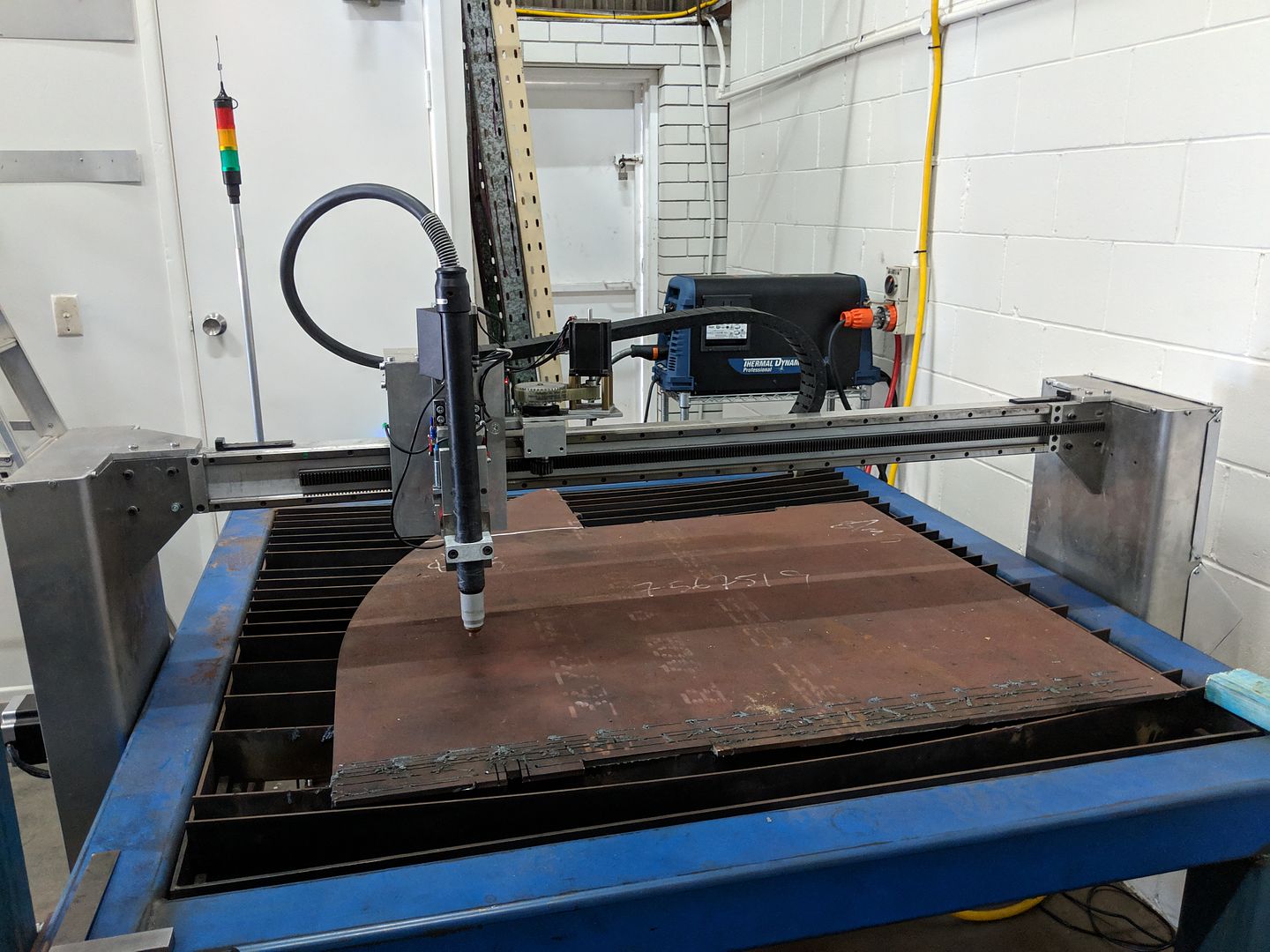
Its kind going to motivate me now I have it all looking shipshape again.
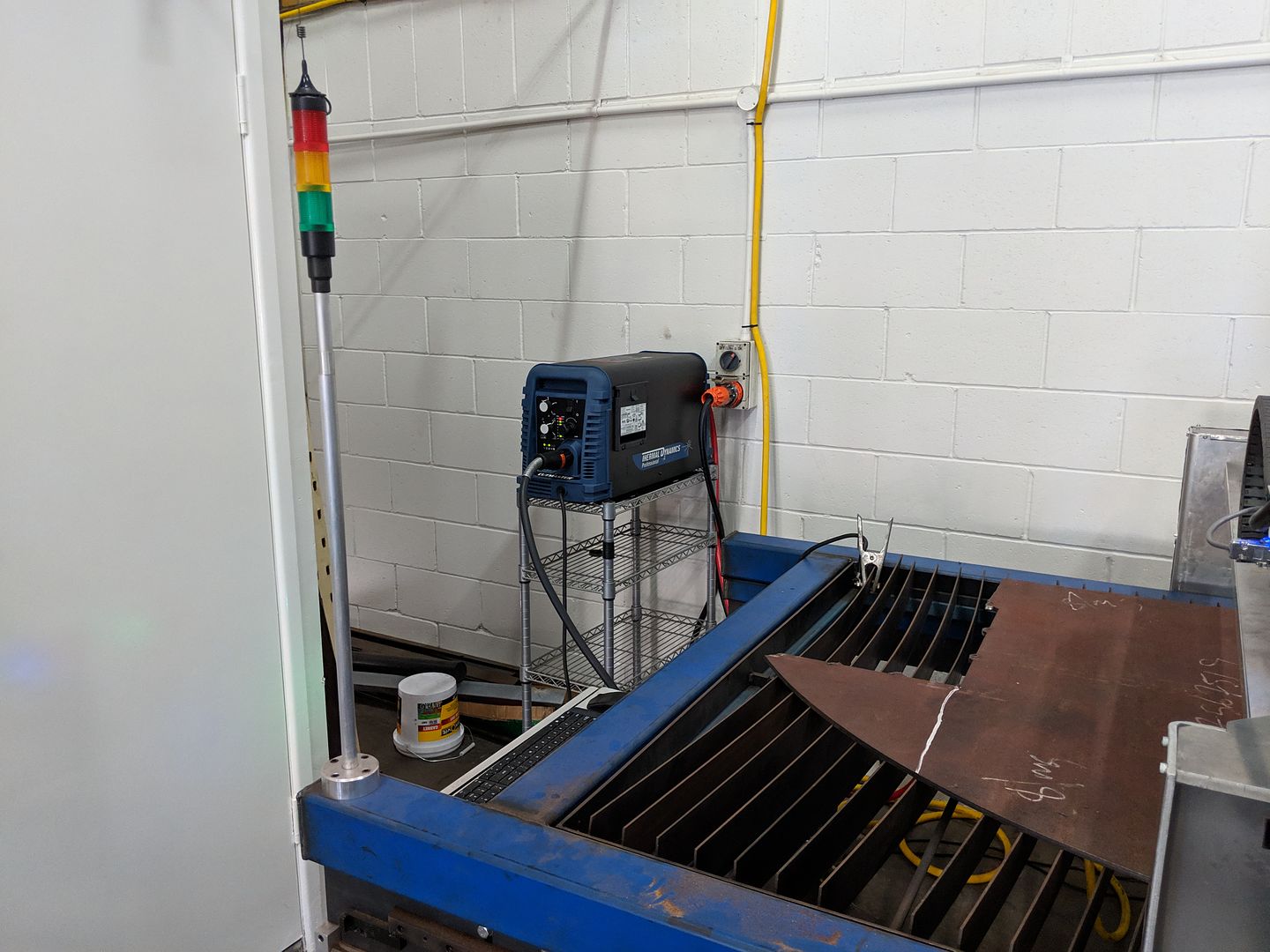
Also put the inverter on a little trolley I had floating around so access to the control panel and the air regulator is easy to get to.
Thanks Peter, I've probably tried harder than most to get the EO THC control to work and it oscillates quite badly. There is one more thing I want to test and that is to move the component onto another slower thread. If that shows no improvement, I'll be following the path of Skunkworks, islander261 et. al. or trying out PhillC's system.
The reason I want to slow down the THC thread is that Jim Colt from Hypertherm has said trying to control the Z too tightly or adjusting too quickly results in oscillations. Also, a paper I found on Industrial PID control said that motors should not be controlled too tightly and need to be given time to make a correction or you will oscillate around the set point. I might be wrong, but I think that trying to control a motor driven axis based on a rapidly fluctuating voltage is quite different to the normal PID based servo control of LinuxCNC and the current EO THC paradigm. I know some THC's get down as slow as 64 Hz.
From some of the data collection I did, I think about 200 Hz might be a good starting point which will let most offset corrections complete before changing it again (on my hardware velocity and acceleration) . I also wrote some code that calculated a moving average so perhaps a 5 sample moving average at 1000 Hz could be paired with the THC thread that is running 5x slower to match the two sampling methods.
So now I have a third reason to try this, becasue PCW suspects that the maximum stable Z axis loop control bandwidth is reduced by the EO.")
I sorted out the air supply and reassembled my table with the torch fitted yesterday and today, I should get the interconnect cable wired in so will be ready to cut something! The new 100slv torch is much heavier than my earlier one so I think I need to rethink my magnetic breakaway. I think I'll just buy a commercial one. snapncut.com/
Its kind going to motivate me now I have it all looking shipshape again.
Also put the inverter on a little trolley I had floating around so access to the control panel and the air regulator is easy to get to.
I believe "skunkworks" found this out also...
I suspect that the external offsets data path (from offset to commanded position) has one or more servo thread pipeline delays so reduces the maximum stable Z axis loop control bandwidth.
Thanks Peter, I've probably tried harder than most to get the EO THC control to work and it oscillates quite badly. There is one more thing I want to test and that is to move the component onto another slower thread. If that shows no improvement, I'll be following the path of Skunkworks, islander261 et. al. or trying out PhillC's system.
The reason I want to slow down the THC thread is that Jim Colt from Hypertherm has said trying to control the Z too tightly or adjusting too quickly results in oscillations. Also, a paper I found on Industrial PID control said that motors should not be controlled too tightly and need to be given time to make a correction or you will oscillate around the set point. I might be wrong, but I think that trying to control a motor driven axis based on a rapidly fluctuating voltage is quite different to the normal PID based servo control of LinuxCNC and the current EO THC paradigm. I know some THC's get down as slow as 64 Hz.
From some of the data collection I did, I think about 200 Hz might be a good starting point which will let most offset corrections complete before changing it again (on my hardware velocity and acceleration) . I also wrote some code that calculated a moving average so perhaps a 5 sample moving average at 1000 Hz could be paired with the THC thread that is running 5x slower to match the two sampling methods.
So now I have a third reason to try this, becasue PCW suspects that the maximum stable Z axis loop control bandwidth is reduced by the EO.
Please Log in or Create an account to join the conversation.
- islander261
- Offline
- Platinum Member
-
Less
More
- Posts: 757
- Thank you received: 216
24 Jan 2019 21:48 #124766
by islander261
Replied by islander261 on topic Rods "Spaceship" Scratch built Plasma Cutter build
Rod
I'll get back to you with more of my THC thoughts later, I'm in the middle of production work this afternoon.
It looks like your table is in the back of your shop. Please get your ventilation sorted out before start cutting!
John
I'll get back to you with more of my THC thoughts later, I'm in the middle of production work this afternoon.
It looks like your table is in the back of your shop. Please get your ventilation sorted out before start cutting!
John
Please Log in or Create an account to join the conversation.
- andypugh
-

- Offline
- Moderator
-
Less
More
- Posts: 19879
- Thank you received: 4643
24 Jan 2019 23:07 #124773
by andypugh
You wouldn't normally do that by slowing the thread, you do that by turning the gains down.
Have you tried lower gains? I think I would expect it all to be handled mainly by I gain.
Replied by andypugh on topic Rods "Spaceship" Scratch built Plasma Cutter build
The reason I want to slow down the THC thread is that Jim Colt from Hypertherm has said trying to control the Z too tightly or adjusting too quickly results in oscillations. Also, a paper I found on Industrial PID control said that motors should not be controlled too tightly
You wouldn't normally do that by slowing the thread, you do that by turning the gains down.
Have you tried lower gains? I think I would expect it all to be handled mainly by I gain.
Please Log in or Create an account to join the conversation.
- rodw
-
Topic Author
- Offline
- Platinum Member
-
Less
More
- Posts: 12035
- Thank you received: 4107
24 Jan 2019 23:12 #124775
by rodw
Replied by rodw on topic Rods "Spaceship" Scratch built Plasma Cutter build
Yes I need to make the downdraft hopper I designed and there is a back door behind the inverter which will do to run the duct out for now for casual cutting. Power might be an issue as well. Its on a 32 amp circuit, the manual suggests a 60 amp circuit and we only have 50 amps coming in from the main board.... Annoying, the standard 3 phase connection should be 63 amps. I think also I need to look at a refrigerated drier too but I do have good filtering and a small desiccant drier on the plasma table. One thing at a time...
One thing I did notice is that the Z axis is stalling on up travel due to the heavier torch so some tweaks are required in my config as I was trying to squeeze everything out of the stepper...
One thing I did notice is that the Z axis is stalling on up travel due to the heavier torch so some tweaks are required in my config as I was trying to squeeze everything out of the stepper...
Please Log in or Create an account to join the conversation.
Time to create page: 0.178 seconds