Rods "Spaceship" Scratch built Plasma Cutter build
- islander261
- Offline
- Platinum Member
-

Less
More
- Posts: 757
- Thank you received: 216
29 Jan 2019 16:54 #125176
by islander261
Replied by islander261 on topic Rods "Spaceship" Scratch built Plasma Cutter build
Rod
It does look like your THC is still a bit "nervous" considering the the thickness (flatness) of the sheet you were cutting. This is pretty exciting as I want to see a working EO PID solution that does away with all the muxing and scaling feedback to keep the motion planner happy (ferror).
A simple way to limit acceleration may be to insert a limit2 component between your Z axis PID component and the step generator. The load pin can be used so that it is only applied when under THC. You may have to use a limit3 before the PID if your axis PID does as much hard limiting as mine. I will not have any time to try this before the end of next month because of travel.
John
Please Log in or Create an account to join the conversation.
- Grotius
-

- Offline
- Platinum Member
-
Less
More
- Posts: 2419
- Thank you received: 2348
29 Jan 2019 18:16 - 29 Jan 2019 18:20 #125190
by Grotius
Replied by Grotius on topic Rods "Spaceship" Scratch built Plasma Cutter build
John,
I see no problem using pid. All the thc work is normally done by one component.
It's up to the component level to make plasma cutting very easy for users. Maybe rod can add a simple timer to his used component to add a reaction delay in ms. This will solve his nervous floating cutting head to a much more stable floating head.
I dont know wich component he is using, but reacting z axis value after 5v plasma difference voltage is normal. Using this feature will eliminate nervous behaviour at the begin stage. My advice is 5v is 0.5mm reaction.
Last edit: 29 Jan 2019 18:20 by Grotius.
Please Log in or Create an account to join the conversation.
- rodw
-
 Topic Author
- Offline
- Platinum Member
-
Less
More
- Posts: 11968
- Thank you received: 4079
29 Jan 2019 21:07 #125206
by rodw
Replied by rodw on topic Rods "Spaceship" Scratch built Plasma Cutter build
Thanks for the support guys. It looks like you really want me to nail this. The support is so much appreciated.
Grotius, I had a look at the opa code and its essentially using the same technique for scaling, just its dealing with a much simpler and predictable geometric shape. The component I am using is the eoffset_pid.comp component from the original external offsets code. It has been removed from master branch when the eoffsets was incorporated because it did not work.
John your idea of the limit 2 makes some sense. The EO adjustments must pass through the PID to reach the stepgen. I guess we also have control of this by manipulating the ini file max velocity and max acceleration settings and I do have a tuning window for them. I did not have much luck with it except to notice yesterday that reducing the acceleration increased oscillations.
I thought the other thing to do is to add a mult2 component on the eoffset-pid output to the axis eoffset counts. This would allow me to reduce the calculated number of adjustment steps applied to the offset which hopefully might prevent overshoot
Grotius, with regard to the reaction delay, I did think of writing a skip component that ignored some servo cycles and only applied an offset on every second or third servo cycle. This also would allow time for a motor to move to the offset position before asking for further adjustment.
Anyway, the feedback all helps to make me think! We all know a lot more then when we started this journey so I'm confident we are close to a result!
Please Log in or Create an account to join the conversation.
- islander261
- Offline
- Platinum Member
-
Less
More
- Posts: 757
- Thank you received: 216
29 Jan 2019 21:50 #125211
by islander261
Replied by islander261 on topic Rods "Spaceship" Scratch built Plasma Cutter build
Rod
I don't think you need to use the mult2 component if you want to change the scaling. As I recall you can set the EO error to counts and the reciprocal independently using the appropriate pins. I recall trying many combinations and never really hit a sweet spot but feel I understand the problem much better now so it might be worth another try.
Right now I am limiting my max Z velocity at 110ipm when under THC and the acceleration is the same for axis moves and THC at .145g (55ips^s). So I guess about the best I can do is a 30 degree slope on the 2mm plate I use.
Did limiting the Z axis acceleration under THC change the frequency of the oscillation or the amplitude or both? If you look at the output of the Z PID and compare it to the actual arc voltage it should be clear if you are overshooting or undershooting the response.
John
Please Log in or Create an account to join the conversation.
- tommylight
-

- Offline
- Moderator
-

Less
More
- Posts: 21666
- Thank you received: 7400
29 Jan 2019 21:53 #125212
by tommylight
Replied by tommylight on topic Rods "Spaceship" Scratch built Plasma Cutter build
You can try all of the above mentioned, or you could do it the crude way, namely get some capacitors with different values and wire one directly to the input of the THCAD. That would slow down the voltage fluctuations and ultimately the THC response.
I have 2 THC of my own design, made to do over 10Khz of sampling and corrections, and that has proven very unnecessary, and troublesome i might add. Adding some low value capacitor to the A/D converter input was the only thing needed to slow it down to very usable levels. One of them is in production work for the last year working perfectly. The second one i will try to install in the following days if time permits.
Mind the polarity and try it with a 1uF/50V at first, see how the Z axis reacts.
BTW, Proma does use relays on the ouptuts, very small ones so they are pretty fast. On a fine tuned machine it can do at least 2" over a foot of length easily ( that is 5cm over 30cm length ). It can do much more but requires the toma config to adjust the reaction speed.
Please Log in or Create an account to join the conversation.
- rodw
-
Topic Author
- Offline
- Platinum Member
-
Less
More
- Posts: 11968
- Thank you received: 4079
29 Jan 2019 22:46 - 29 Jan 2019 22:47 #125218
by rodw
Replied by rodw on topic Rods "Spaceship" Scratch built Plasma Cutter build
Thanks guys. I'm not really sure if reducing the acceleration response will help much with the model I'm using. Here is a plot with reduced acceleration and greater oscillation
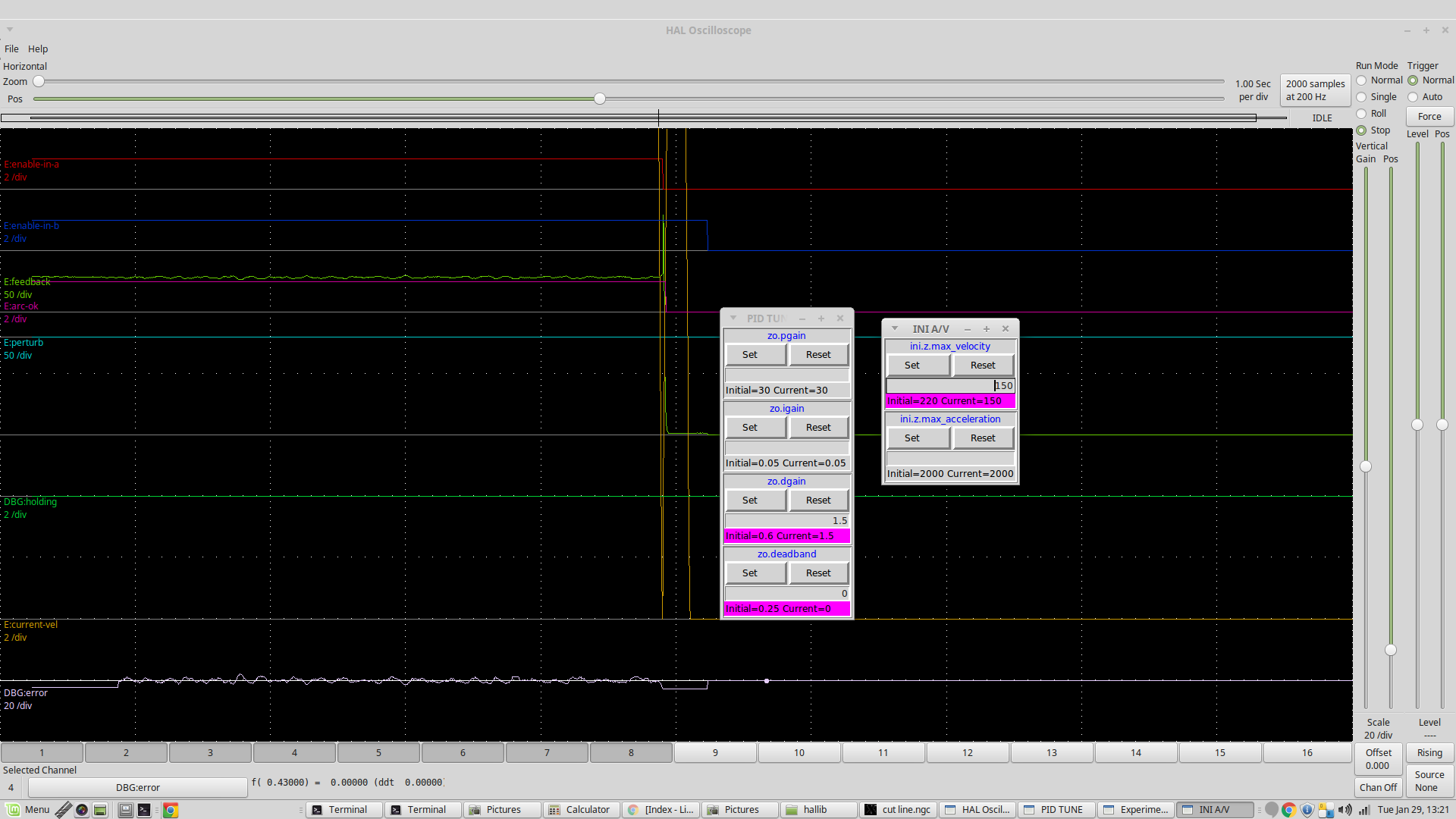
You can compare that with plots a couple of pages ago.
Tommy, I'm not really a hardware guy and Dewey cautioned against any type of filtering. I know Peter suggests a lowpass filter on the torch volts which I have not added. Skunkworks mentioned PCW suggested a lowpass gain of 0.02 from memory. If you go back a couple of pages, you will see a voltage plot with no THC and its very smooth. The other smoothing technique used in plasma is to compute a moving average. I've written a component to do this for kerf crossing and I was going to break it out as a standalone component.
The more I think about this, the eoffset counts are held in an accumulator register that is reduced every time the counts are applied to the trajectory. This is fine in a geometric sense if you are machining a cam lobe as its a steady state but in the case of torch volts, we have a random signal. I kind of think that the offset adjustments are stacking up before the hardware can fully apply the adjustment. I think I will write a skip component that if configured for say a skip 3, it will hold the eoffset adjustment to zero for two cycles and then apply an adjustment on the third. The offsets will still be correctly calculated but hopefully, the hardware has time to reach its adjusted position.
Then the next approach might be to scale the offset before applying it.
Last edit: 29 Jan 2019 22:47 by rodw.
Please Log in or Create an account to join the conversation.
- islander261
- Offline
- Platinum Member
-
Less
More
- Posts: 757
- Thank you received: 216
29 Jan 2019 23:40 #125229
by islander261
Replied by islander261 on topic Rods "Spaceship" Scratch built Plasma Cutter build
Rod
It is really hard looking at screen shots at the chosen scales to tell much. It does look like the frequency of oscillation reduced by about 30% when using the limited acceleration. By counting I got about 10hz on the first example and about 6 hz or 7hz on this last one. The voltage scales are too coarse to really tell much about the amplitude on the screen shots but look to be about the same. Your just going to have to do the measurements off a live halscope so you can expand scales and get real numbers. At this point I think keeping the maximum velocity up to the normal axis velocity and reducing the acceleration to around 980mmps^2 (.1g) is about right and maybe even go to 98mmps^2 (.01g). Right now you are trying to run your Z under THC quite a bit faster than I am. Tommy's 2"/12" is a much slower response than I am using and even slower again to what your settings indicate you are trying to achieve.
The inner workings of the EO aren't that clear to me. I figured we just kept correcting the error until it was gone like a normal PID. If the error has not been removed during the first period we don't zero it out for a normal PID. Is this part of the problem applying position corrections twice in series?
John
Please Log in or Create an account to join the conversation.
- rodw
-
Topic Author
- Offline
- Platinum Member
-
Less
More
- Posts: 11968
- Thank you received: 4079
30 Jan 2019 01:32 #125239
by rodw
Replied by rodw on topic Rods "Spaceship" Scratch built Plasma Cutter build
John,Thanks I forgot to mention we trick the external offsets into using 100% of the actual velocity and accel by doubling the real values in the ini and applying a 50% offset ratio so you need to halve the values shown. We can do this because THC control and normal axis movement is mutually exclusive. So I'm actually similar to your settings (1000 mm/sec/sec accel vs your 980).
I've written this component this morning which will allow me to both scale the output from eoffset_pid.comp and also skip some servo cycles. I'll see how it goes once I get it installed.
I've written this component this morning which will allow me to both scale the output from eoffset_pid.comp and also skip some servo cycles. I'll see how it goes once I get it installed.
Warning: Spoiler!
omponent eoskipscale "Skips servo cycles for eoffset and also scales output";

author "Rod Webster";
pin in float		in 				"eoffset_pid count in";
pin out float		out 			"eoffset_pid count out";
pin in float		scale = 1.0 	"scale to apply";
pin in unsigned		skip_num = 1 	"Number of cycles to skip (1 = none)";
pin in bit			enable 			"true to enable adjustments"
;
function _;
license "GPL";
;;
unsigned skip = 0;

FUNCTION(_)
{
	if(enable){
		if(skip_num == 1){	// nothing to skip
		  out = in * scale;
		}
		else{
			skip++;
			if(skip >= skip_num){
				out = in * scale;
				skip = 0;
			}
			else
				out = 0;
				skip++;
		}
	}
	else
		out = in;
}
Please Log in or Create an account to join the conversation.
- phillc54
-

- Offline
- Platinum Member
-
Less
More
- Posts: 5711
- Thank you received: 2100
30 Jan 2019 01:32 #125240
by phillc54
If that is the case then you need to calculate how much movement one offset count would cause, calculate the maximum amount of movement per period from your maximum velocity then limit the number of counts the THC can output per period to suit this maximum movement per period.
Cheers, Phill.
Replied by phillc54 on topic Rods "Spaceship" Scratch built Plasma Cutter build
rodw wrote:
I kind of think that the offset adjustments are stacking up before the hardware can fully apply the adjustment.
If that is the case then you need to calculate how much movement one offset count would cause, calculate the maximum amount of movement per period from your maximum velocity then limit the number of counts the THC can output per period to suit this maximum movement per period.
Cheers, Phill.
The following user(s) said Thank You: rodw
Please Log in or Create an account to join the conversation.
- islander261
- Offline
- Platinum Member
-
Less
More
- Posts: 757
- Thank you received: 216
30 Jan 2019 04:05 #125250
by islander261
Replied by islander261 on topic Rods "Spaceship" Scratch built Plasma Cutter build
I am not sure this going to quite do it. I will actually be surprised if the Z axis ever gets up to full velocity given the short distances involved and the short time periods we are looking at. If this is actually a case of inadequate acceleration then we need to significantly increase the power we are putting into our Z axis so we can accelerate fast enough. This may be part of the reason all the high dollar commercial THCs actually use servo motors to drive them. I have an old Animatics Smart Motor here that I could try but it is so under powered I doubt it will be an improvement. So my money is still on a delay some where that is causing the mechanics to overshoot the correct position.
I forgot about the .ini values for velocity and acceleration being twice what is actually applied under EO when the stock .5 AV ratio is used. I just assumed that your adjustments were the actual values used. I still believe that slowing down the acceleration will help or cure the problem. After all skipping PID update times is just doing the same thing by a different method.
John
Please Log in or Create an account to join the conversation.
Time to create page: 0.221 seconds