Rods "Spaceship" Scratch built Plasma Cutter build
- rodw
-
 Topic Author
- Offline
- Platinum Member
-

Less
More
- Posts: 11963
- Thank you received: 4075
30 Jan 2019 04:35 #125253
by rodw
Replied by rodw on topic Rods "Spaceship" Scratch built Plasma Cutter build
Well i tried that component (after fixing some errors). It did not break anything but neither gave a significant improvement. Then I tried slowing down the velocity and acceleration settings as John suggested and it did make a difference by reducing the twitching but the amplitude of the oscillations increaed. Visually not as nervous. The added amplitude may be able to be tuned out.
Phill, thanks for the idea. Its not quite like that. What I mean is the adjustments might become "stale". The external offsets respects the machine velocity and acceleration. so if an offset takes more than one servo period to execute everything is OK, but another offset might be calculated which due to voltage signal hysteresis is more than required (overlaid on the last). I might look at the idea and extend my component to include a limit as the datatype used in the limit components are floats and we need S32. Its probably a better method than just blindly scaling.
Phill, thanks for the idea. Its not quite like that. What I mean is the adjustments might become "stale". The external offsets respects the machine velocity and acceleration. so if an offset takes more than one servo period to execute everything is OK, but another offset might be calculated which due to voltage signal hysteresis is more than required (overlaid on the last). I might look at the idea and extend my component to include a limit as the datatype used in the limit components are floats and we need S32. Its probably a better method than just blindly scaling.
Please Log in or Create an account to join the conversation.
- rodw
-
Topic Author
- Offline
- Platinum Member
-
Less
More
- Posts: 11963
- Thank you received: 4075
30 Jan 2019 04:45 #125255
by rodw
Replied by rodw on topic Rods "Spaceship" Scratch built Plasma Cutter build
Well, here is a slower version. I started to change the pid settings but had to go so I think this will be it for today. I think the range is about 2 volts which is not too bad really. Thats a range of about 0.27mm based on my earlier sampling work, about +- 0.13mm
Please Log in or Create an account to join the conversation.
- islander261
- Offline
- Platinum Member
-
Less
More
- Posts: 757
- Thank you received: 216
30 Jan 2019 18:56 #125318
by islander261
Replied by islander261 on topic Rods "Spaceship" Scratch built Plasma Cutter build
Rod
I tried looking the source code and no surprise I couldn't find the code where the eoffset.counts is processed. As I recall the EO is handled like a jog wheel. This means that only the change in counts each servo period is applied to the position command. So if the error count is constant the motion commanded position will not change. I hope someone with better coding skills than I have can confirm or correct how the EO works.
I have trouble reading your arc voltage well because of the scale but on the screen shot it appears to be holding at +/- 5 volts. I think that is an acceptable number if the cut quality is ok. I usually display my arc voltage at 10v per division so I can count the tic marks on the screen. I understand that with the TD torch your arc voltage may be over 100v.
I have some ramblings here about how my system responds that may be helpful or not. Assuming a linear arc voltage to distance relationship a 1volt change in arc voltage is equal to .000946 inches of arc length, to make things simple lets call that .001". When using the HT Duramax torch they say you need to hold the torch height to +/- .005" of the set point height which works out to about +/- 5 volts in my case. When cutting long straight cuts and cuts without the corner lock becoming active I usually have the arc voltage vary by less than +/- 1 volt. This is on 2mm HRS which is never flat when being cut! The Z axis acceleration on my system right now is 55ips^s (.145g). This works out to distance traveled the first servo period of a correction of .0000275", not vary far. So to correct for a 1 volt error in arc voltage it will take about .006 seconds ( 6 servo periods) reaching a velocity of .332ips, well within the step gen limits I use. Now with 10:1 micro stepping and a .2"/revolution lead screw the resolution is .0001" per step so 10 steps to correct for that same 1 volt error in arc voltage. Now I am not sure why my Z axis wants oscillate at 10hz (.1s period) which is quite slow compared to the movement that can be achieved, can this be the current ripple on the plasma power supply output?.
John
Please Log in or Create an account to join the conversation.
- Grotius
-

- Offline
- Platinum Member
-
Less
More
- Posts: 2419
- Thank you received: 2348
30 Jan 2019 19:27 #125320
by Grotius
Replied by Grotius on topic Rods "Spaceship" Scratch built Plasma Cutter build
I think Rod can make his plasma cutter working like magic. He is a good c programmer, so i do not worry about his program skills.
At the time i build my plasma component. I did it step by step. It takes time. But in the end. It's powerfull !!
At the time i build my plasma component. I did it step by step. It takes time. But in the end. It's powerfull !!
The following user(s) said Thank You: rodw
Please Log in or Create an account to join the conversation.
- rodw
-
Topic Author
- Offline
- Platinum Member
-
Less
More
- Posts: 11963
- Thank you received: 4075
30 Jan 2019 19:54 - 30 Jan 2019 19:56 #125325
by rodw
Replied by rodw on topic Rods "Spaceship" Scratch built Plasma Cutter build
John, yes, the eoffsets is now documented in the master branch motion component.
linuxcnc.org/docs/devel/html/man/man9/motion.9.html
Basically the counts are added to an internal register and each count is scaled and used to adjust the axis position.
The voltage in that last post is holding to within a 2 volt range and oscillating at about 4 Hz vs a nervous 8-9 Hz a few days ago. Earlier in this thread I posted a graph from my old machine that showed a linear relationship of 7.53 V/mm (or 0.132 mm/volt). I'm going to assume this machine is similar as the last config seemed to work OK on it. So the 2 volt range is well within spec at +- 0.13mm as I quoted in my last post. So it would seem that from what you've said this morning (on my side of the world) is we are now well within spec so I think its about time I started to lock this config down.
On this thread which I started right at the beginning of my build, Tommy quotes some acceleration settings he uses.
forum.linuxcnc.org/30-cnc-machines/31509...pinion-drive?start=0
In an effort to get better tracking we pushed the velocity and acceleration way past that. So now in the light of a heavier torch and observing that we halved the oscillation frequency at slower velocity and acceleration, I think I'll retreat to
60mm/sec velocity and 700 mm/sec/sec or less acceleration and see what happens.
I thought I should plot the external offset count inputs to see how big of an adjustment we are asking for each servo cycle. I quite like the idea Phill suggested of applying a limit on the counts requested. To accelerate from 0 to 60 mm/sec will take 7 servo cycles on in the case of a reversal of direction, thats 1.4 seconds if at full velocity (which I doubt will be reached). At 60 m/sec, the maximum counts that can be executed per servo cycle is 23. I think i will tweak my component posted earlier to allow a limit to be applied to a S32.
Finally, I think I will enhance my component that scales the THCAD voltage to include low pass filtering PCW suggests and also to move my average volts code into this component so there are a couple of methods to smooth the arc voltage input.
Phew, sorry about my ramblings!
Last edit: 30 Jan 2019 19:56 by rodw.
Please Log in or Create an account to join the conversation.
- islander261
- Offline
- Platinum Member
-
Less
More
- Posts: 757
- Thank you received: 216
30 Jan 2019 20:58 #125341
by islander261
Replied by islander261 on topic Rods "Spaceship" Scratch built Plasma Cutter build
Rod
Thanks, I am aware of the newer entries in the sparse at best motion documentation. I was hoping that one of the code wizards will look up in the code and confirm that EO works like the jogging input. I just don't know how to follow the changing variable names through the succession of files.
You can limit the actual EO counts but I think it will be more effective to use a limit2 or limit3 component depending on where it is placed. I know at least one implementation that uses three different fixed levels plus one user settable acceleration limits that are chosen depending on sheet thickness and cutting speed.
I think you are well within the sweet spot with your +/-2volt ripple using the TD equipment.
John
Please Log in or Create an account to join the conversation.
- Mike_Eitel
-

- Offline
- Platinum Member
-
Less
More
- Posts: 1052
- Thank you received: 183
30 Jan 2019 22:28 #125348
by Mike_Eitel
Replied by Mike_Eitel on topic Rods "Spaceship" Scratch built Plasma Cutter build
Hi Rod
Just by curiosity.
Do you know what mechanical resonating frequency you z axis has?
Mike
Just by curiosity.
Do you know what mechanical resonating frequency you z axis has?
Mike
Please Log in or Create an account to join the conversation.
- islander261
- Offline
- Platinum Member
-
Less
More
- Posts: 757
- Thank you received: 216
31 Jan 2019 00:23 #125356
by islander261
Replied by islander261 on topic Rods "Spaceship" Scratch built Plasma Cutter build
All
Ok, I found the answer in control.c.
So yes it does act like a jog wheel.
John
Ok, I found the answer in control.c.
...
        new_eoffset_counts       = *(axis_data->eoffset_counts);
        delta                    = new_eoffset_counts - axis->old_eoffset_counts;
        axis->old_eoffset_counts = new_eoffset_counts;
...
        axis->ext_offset_tp.pos_cmd   += delta *  *(axis_data->eoffset_scale);
...
So yes it does act like a jog wheel.
John
Please Log in or Create an account to join the conversation.
- rodw
-
Topic Author
- Offline
- Platinum Member
-
Less
More
- Posts: 11963
- Thank you received: 4075
31 Jan 2019 01:00 - 31 Jan 2019 01:09 #125362
by rodw
Replied by rodw on topic Rods "Spaceship" Scratch built Plasma Cutter build
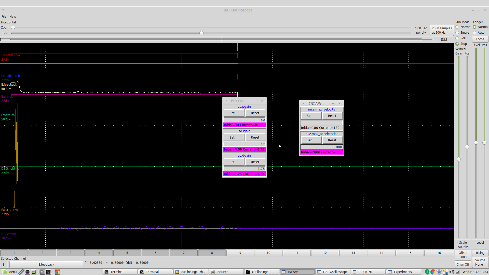
Well I think I will go with this one.

The error line at the bottom is a 2 volt/division scale stays within +- 2 volts but most of the time its better than that.
I did get tighter control than this at the expense of more busyness!
I did try the lowpass filter thats a bad idea with external offsets. I ended up with very large (but smooth) oscillations
Attachments:
Last edit: 31 Jan 2019 01:09 by rodw.
Please Log in or Create an account to join the conversation.
- islander261
- Offline
- Platinum Member
-
Less
More
- Posts: 757
- Thank you received: 216
31 Jan 2019 01:57 #125363
by islander261
Replied by islander261 on topic Rods "Spaceship" Scratch built Plasma Cutter build
Rod
Yes, that was my experience with any lowpass filtering of the arc voltage, either digital or analog before the THCAD. I am thinking that the 6hz-7hz is way below any typical noise source so it must be related to something mechanical or in the plasma power supply. Have you tried the THCAD with a 1:1 output? If any thing noting any change may help pinpoint the source. Have you checked the error voltage at fixed height again after all the changes? Have you checked the actual distance the torch is moving while cutting under THC? Seeing the phase relationship between the error voltage/counts and the change in torch distance will give a clue which way to move with tuning the response. No matter what I did the voltage lagged the distance (commanded steps).
The eoffset PID component probably needs to be re tuned for each new set of output response limiting, especially the D term. I know Dewey put in some pins to make the imperial and metric scales close to reacting the same. I have no idea if it works correctly. I think your gains looks a little high. For the slope of my error volts to distance curve a P gain of 10 to 11 looks to be a good starting place, for some reason you are a factor of 10 greater than that. With your TD torch I would expect your gain numbers to be about twice mine if the imperial/metric compensation works correctly. Of course all this is out the window if you are good with your cut quality.
John
Please Log in or Create an account to join the conversation.
Time to create page: 0.273 seconds