"Origami" CNC Plasma Build - folding 1200 x 600mm cut area
- Joco
-
 Topic Author
- Offline
- Platinum Member
-

Less
More
- Posts: 532
- Thank you received: 327
02 Apr 2021 21:39 - 03 Apr 2021 19:33 #204564
by Joco
"Origami" CNC Plasma Build - folding 1200 x 600mm cut area was created by Joco
So, for when you don't have enough projects to do/finish what do you do? You start a new one. 
General design concept and some kit on hand and on order to get the ball rolling:
Intent and Design Params
Kit on hand and ordered
I'm taking inspiration and guidance from some of the great work and designs from the plasma/laser forum so hopefully nothing too experimental in all this.
I'm in the middle of trying to get some working designs that will inform steel/aluminium to be to start the fabrication part of the build. Given I'm at the start of a 10 days off work (long weekend and some annual leave) I need to get that sorted so I can buy some steel and get cutting/bolting/welding.
I'll post pics and plans as things progress and solidify. Also any advice on gotcha's to be aware of please feel free to chime in.
Cheers - J.
General design concept and some kit on hand and on order to get the ball rolling:
Intent and Design Params
- Able to fold up into a vertical position so can be slotted into availabe space when not in use
- On wheels so can be moved out to driveway for use
- Cut area to allow local standard sheets of 1220x2400 to be indexed through the machine
- Buildable on a lean to moderate budget
- Frame strength able to cope with full width sheets of 3-4mm steel. Able to cope with circa 300x500mm plates of 10-12mm steel
- Gantry to be light weight as practical to allow for good speed while using more hobby grade motors
- If possible start out for a simple manual fill/empty water table. But also able to cut dry and wash/vacum out the dust before returning to garage
- Try and allow for potential expansions/additions later. Such as auto fill/empty water table.
- Good/Easy/Effect UI to be used. QTPlasmac being the obvious answer. But I also liked where monokrom was heading and being QTPyVCP based I was more comfortable with that and being able to tweak as I saw fit.
Kit on hand and ordered
- Plasm unit - Cigweld Cutskill 60. "Blowback" style start, no HF
- DMA860H stepper drivers. Yes these are overkill but the are also the same units used on cnc mill so keeping this common means I essentially have temporary spares if I need to fix something asap. Plus they seem to work really well and never get hot.
- Nema23, 3A, 1.2Nm, 2.4mH motors - 3 of them for X and Y. If for some reason I need to upgrade I can as drivers have plenty of head room.
- DM542Y stepper driver. Will also cover a Nema23 if the Nema17 on Z proves unable to cut it
- Nema17, 2A, 0.59Nm, 3.0mH motor - for Z axis. Plan to direct drive the motor to the leadscrew
- HTD 3M timing belt, 15mm wide, steel core for the X and Y travel
- HTD 3M timing belt and 3:1 gearing reduciton for motor connection to drive pulley on X and Y
- Pillow blocks for the reduction gearing meachanisim
- 48V, 10A psu on hand to drive things
- Multiple Core2 PCs to choose from - all tested and proven to be low latency under RTAI and RT kernels
- Mesa 7i76e
- 15" Elo touch screen - proven to work before moving cnc mill to 1080p screen
- Mean Well MDR-40-24V psu for field power
- Mean Well HDR-15-24V for ohmic hyper sensing
I'm taking inspiration and guidance from some of the great work and designs from the plasma/laser forum so hopefully nothing too experimental in all this.
I'm in the middle of trying to get some working designs that will inform steel/aluminium to be to start the fabrication part of the build. Given I'm at the start of a 10 days off work (long weekend and some annual leave) I need to get that sorted so I can buy some steel and get cutting/bolting/welding.
I'll post pics and plans as things progress and solidify. Also any advice on gotcha's to be aware of please feel free to chime in.
Cheers - J.
Last edit: 03 Apr 2021 19:33 by Joco. Reason: Added more items on order
Please Log in or Create an account to join the conversation.
- rodw
-

- Away
- Platinum Member
-
Less
More
- Posts: 12012
- Thank you received: 4096
03 Apr 2021 02:16 #204587
by rodw
Replied by rodw on topic "Origami" CNC Plasma Build - folding 1200 x 600mm cut area
All sounds pretty good. the NEMA 17 should work. Keep the torch holder light!
48V, 10A with those drivers will be quite good. What I did on the spaceship when I started (with DM542a drivers)
re reduction setup, focus on the distance travelled per motor revolution. There are recommendations in the Plasma primer. Don't go over 30mm per rev (what I have) 15-25mm would be a better range.
Please Log in or Create an account to join the conversation.
- andypugh
-

- Offline
- Moderator
-

Less
More
- Posts: 19875
- Thank you received: 4642
03 Apr 2021 16:57 - 03 Apr 2021 16:57 #204641
by andypugh
I have a design idea low down my list for a folding plasma table.
The idea is to use a CoreXY mechanism, with hinges in the middle of the two short sides.
Folding the hinges in slackens all the belts (or, possibly, bicycle chains) allowing the gantry to slide into a diagonal position.
The legs need castors for this to work. But then the whole thing can be parked against the wall.
If you do it, that's great, I can take it off my list.
Clearly this would be hard to combine with a water table.
Replied by andypugh on topic "Origami" CNC Plasma Build - folding 1200 x 600mm cut area
Able to fold up into a vertical position so can be slotted into availabe space when not in use
I have a design idea low down my list for a folding plasma table.
The idea is to use a CoreXY mechanism, with hinges in the middle of the two short sides.
Folding the hinges in slackens all the belts (or, possibly, bicycle chains) allowing the gantry to slide into a diagonal position.
The legs need castors for this to work. But then the whole thing can be parked against the wall.
If you do it, that's great, I can take it off my list.
Clearly this would be hard to combine with a water table.
Last edit: 03 Apr 2021 16:57 by andypugh.
Please Log in or Create an account to join the conversation.
- Joco
-
Topic Author
- Offline
- Platinum Member
-
Less
More
- Posts: 532
- Thank you received: 327
03 Apr 2021 18:40 #204646
by Joco
Replied by Joco on topic "Origami" CNC Plasma Build - folding 1200 x 600mm cut area
Andy - I came across your musing about a core xy build but hadnt twigged to the folding aspect. For me I’m trying to keep the motion mechanics reasonably “traditional “ for the sake of simplicity. Also i have no wall space free. So flipping the table in the vertical with the hing on the long side creates a space efficient setup while keeping things pretty simple.
So, your core xy is still gonna be on your list.
Now my “wish list” item is a robot arm based machine. :-D
So, your core xy is still gonna be on your list.
Now my “wish list” item is a robot arm based machine. :-D
Please Log in or Create an account to join the conversation.
- Joco
-
Topic Author
- Offline
- Platinum Member
-
Less
More
- Posts: 532
- Thank you received: 327
03 Apr 2021 19:12 - 03 Apr 2021 19:29 #204649
by Joco
Replied by Joco on topic "Origami" CNC Plasma Build - folding 1200 x 600mm cut area
Rod - good call out on the travel distance. The 3:1 gearing with the drive pulley will give me 20mm of travel per motor revolution. If I need to I can get down to 16mm of travel with a new set of drive pulleys. Hopefully I will be able to get enough rpm from the steppers to get good cut speeds on thin material. Quick rapids wiouild be nice but not necessary. This isn't a production environment after all. But time will tell. The experiemtning and learning is half the fun. 
Re the NEMA17 motor, yes will need a light gantry. Plan is to use aluminium on as much as practical. My plan was to use an M6 or M8 lead screw to start with. It should provide plenty of effective torque for lifting the Z and its dirt cheap to source. The down side might be the speed of travel given the ~1mm pitch. We shall see. I can always change to one of the common 3d printer lead screws later. Similar to what tommylight has used in his very compact Z assembly.
Cheers - J.
Last edit: 03 Apr 2021 19:29 by Joco. Reason: typo
Please Log in or Create an account to join the conversation.
- rodw
-
- Away
- Platinum Member
-
Less
More
- Posts: 12012
- Thank you received: 4096
03 Apr 2021 23:47 #204688
by rodw
Andy, just leave it against the wall and use it too. There are some vertical tables around, Just need a bit of a lean to prop the sheet up. Sheetcam has a tabbing function so small retaining tabs keep parts in place until you snap them out. You could devise a funnel attached to a fume extractor that follows the torch. There is a member here that has an exhaust trough attached to the lower side of his gantry ends too. You need to do this!
Replied by rodw on topic "Origami" CNC Plasma Build - folding 1200 x 600mm cut area
Able to fold up into a vertical position so can be slotted into availabe space when not in use
I have a design idea low down my list for a folding plasma table.
The idea is to use a CoreXY mechanism, with hinges in the middle of the two short sides.
Folding the hinges in slackens all the belts (or, possibly, bicycle chains) allowing the gantry to slide into a diagonal position.
The legs need castors for this to work. But then the whole thing can be parked against the wall.
If you do it, that's great, I can take it off my list.
Clearly this would be hard to combine with a water table.
Andy, just leave it against the wall and use it too. There are some vertical tables around, Just need a bit of a lean to prop the sheet up. Sheetcam has a tabbing function so small retaining tabs keep parts in place until you snap them out. You could devise a funnel attached to a fume extractor that follows the torch. There is a member here that has an exhaust trough attached to the lower side of his gantry ends too. You need to do this!
Please Log in or Create an account to join the conversation.
- rodw
-
- Away
- Platinum Member
-
Less
More
- Posts: 12012
- Thank you received: 4096
03 Apr 2021 23:50 #204690
by rodw
20mm per rev will be perfect. Acceleration is nice on corners. I think the spaceship can get to 2 m/sec which is a normal speed for 2mm mild steel in < 7 ms.
Replied by rodw on topic "Origami" CNC Plasma Build - folding 1200 x 600mm cut area
Rod - good call out on the travel distance. The 3:1 gearing with the drive pulley will give me 20mm of travel per motor revolution. If I need to I can get down to 16mm of travel with a new set of drive pulleys. Hopefully I will be able to get enough rpm from the steppers to get good cut speeds on thin material. Quick rapids wiouild be nice but not necessary. This isn't a production environment after all. But time will tell. The experiemtning and learning is half the fun.
Re the NEMA17 motor, yes will need a light gantry. Plan is to use aluminium on as much as practical. My plan was to use an M6 or M8 lead screw to start with. It should provide plenty of effective torque for lifting the Z and its dirt cheap to source. The down side might be the speed of travel given the ~1mm pitch. We shall see. I can always change to one of the common 3d printer lead screws later. Similar to what tommylight has used in his very compact Z assembly.
Cheers - J.
20mm per rev will be perfect. Acceleration is nice on corners. I think the spaceship can get to 2 m/sec which is a normal speed for 2mm mild steel in < 7 ms.
Please Log in or Create an account to join the conversation.
- Joco
-
Topic Author
- Offline
- Platinum Member
-
Less
More
- Posts: 532
- Thank you received: 327
05 Apr 2021 00:15 #204830
by Joco
Replied by Joco on topic "Origami" CNC Plasma Build - folding 1200 x 600mm cut area
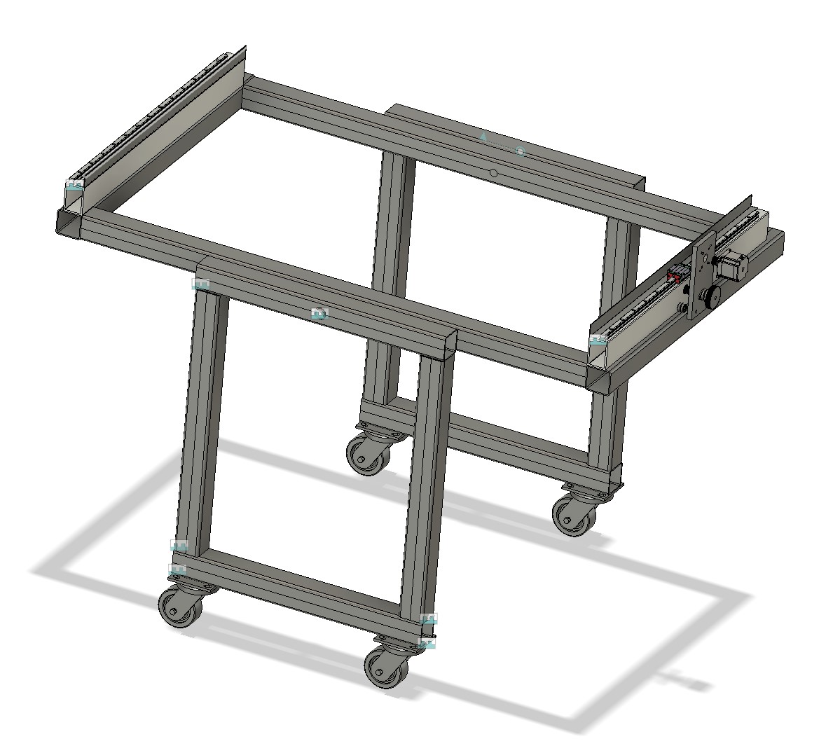
Been fighting with design ideas and have come up with this one. I am still working out the best place to put the cross frame supports. But given how things hinge there are limited options.
Overall dimensions are roughly 1500-1600 on the long length where the gantry will span. Gantry will be 75x50mm Aluminium with a 4mm wall.
About 1000mm wide from outside of each support frame. Support frames about 670mm wide.
Steel SHS is 65mm with a 3mm wall. Standard construction stocked size here in NZ. Should be pretty cheap.
View showing "locked" position. There is the potential with this shape to have locking pins at the top outer edges of the support frames.
View showing storage position:
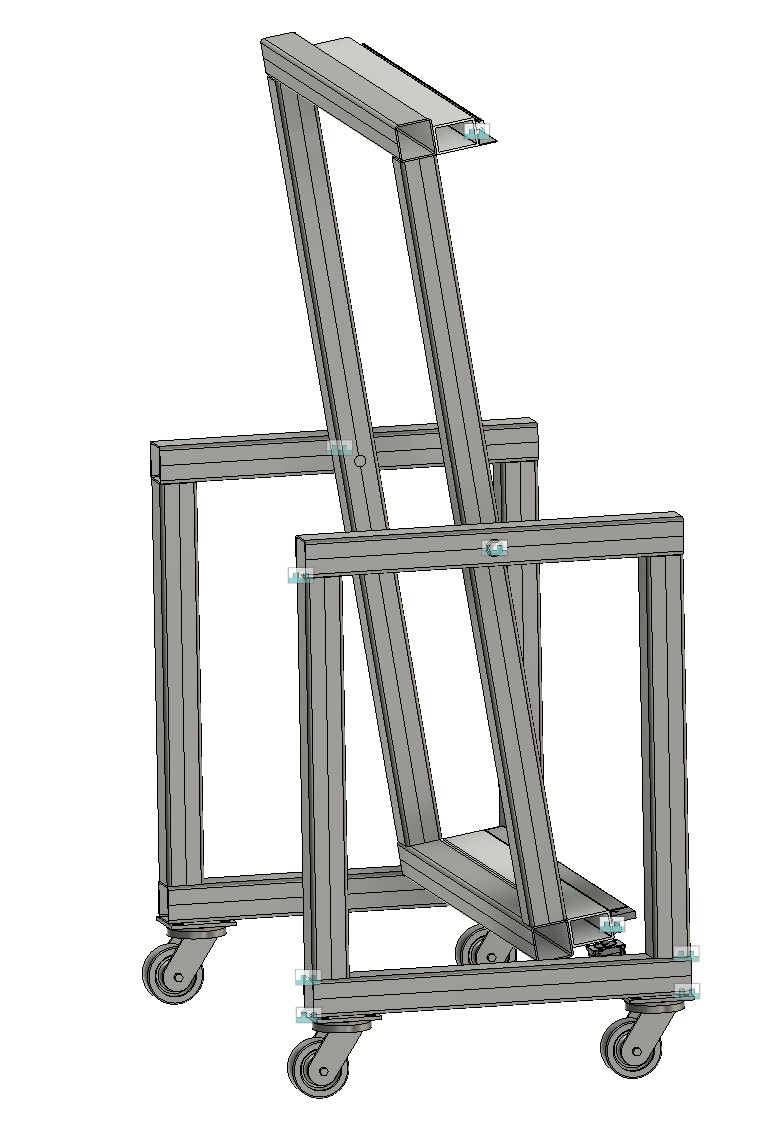
Cheers - J
Overall dimensions are roughly 1500-1600 on the long length where the gantry will span. Gantry will be 75x50mm Aluminium with a 4mm wall.
About 1000mm wide from outside of each support frame. Support frames about 670mm wide.
Steel SHS is 65mm with a 3mm wall. Standard construction stocked size here in NZ. Should be pretty cheap.
View showing "locked" position. There is the potential with this shape to have locking pins at the top outer edges of the support frames.
View showing storage position:
Cheers - J
Attachments:
Please Log in or Create an account to join the conversation.
- rodw
-
- Away
- Platinum Member
-
Less
More
- Posts: 12012
- Thank you received: 4096
05 Apr 2021 00:29 #204831
by rodw
Replied by rodw on topic "Origami" CNC Plasma Build - folding 1200 x 600mm cut area
Why not like this?
The following user(s) said Thank You: hairy
Please Log in or Create an account to join the conversation.
- Joco
-
Topic Author
- Offline
- Platinum Member
-
Less
More
- Posts: 532
- Thank you received: 327
05 Apr 2021 01:06 #204834
by Joco
Replied by Joco on topic "Origami" CNC Plasma Build - folding 1200 x 600mm cut area
I had thought about a vertical table but I have no wall space left to place one. If it was free standing in the slot I plan to use then I will still need it to be on wheels and no more than 1000mm wide. I need it to be on wheels so I can play the reposition dance to work around space limitations.
The other part that looked fiddly to me was when dealing with odd shaped or small cut off parts as the stock to be cut from. This vertical model works super well when doing full or half sheets. Way more fiddly when dealing with small bits. I'm sure doable, just more fiddly. And as a hobby shop I will not be dealing with full/half sheets that often.
Did that do any videos of how they dealt with , say 300mm square bits or a circular offcut that was to be the used to get 3-4 small parts from?
Thanks for the ideas - J.
Please Log in or Create an account to join the conversation.
Time to create page: 0.258 seconds