What do you really get for a $350 desk top engraver ?
- machinedude
-
 Topic Author
- Offline
- Platinum Member
-

Less
More
- Posts: 715
- Thank you received: 312
18 Sep 2024 19:23 #310409
by machinedude
Replied by machinedude on topic What do you really get for a $350 desk top engraver ?
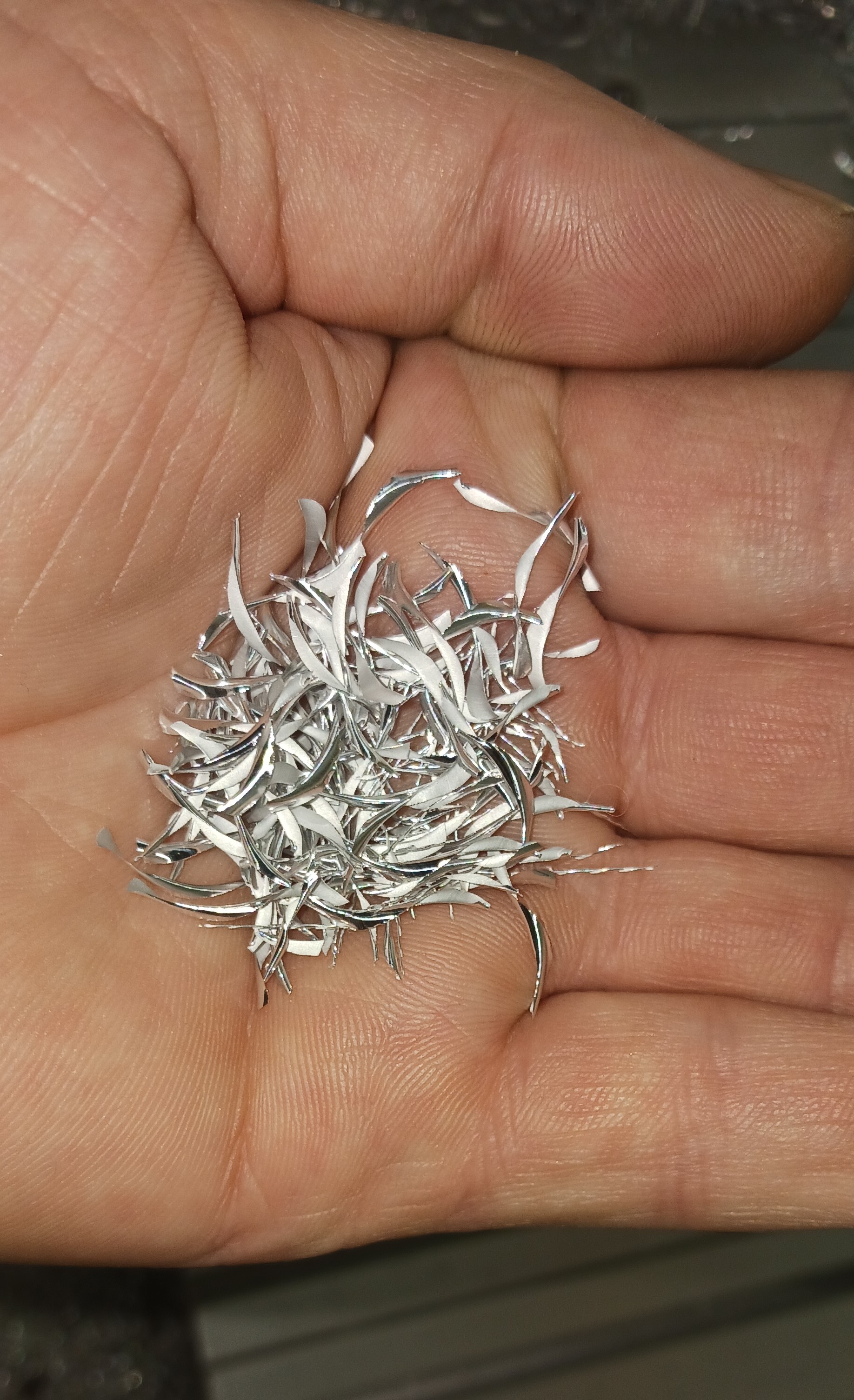
i was not expecting this good of a cut step over or depth of cut for that matter but i probably tripled my step over on my X axis. .600 depth of cut with a .130 step over at @ 75 IMP with a 1/4 diameter 3 flute. the drive did perfect the spindle was starting to drop in rpm slightly. now i'm making some chips 
Attachments:
The following user(s) said Thank You: tommylight, spumco
Please Log in or Create an account to join the conversation.
- machinedude
-
 Topic Author
- Offline
- Platinum Member
-

Less
More
- Posts: 715
- Thank you received: 312
22 Sep 2024 12:04 #310595
by machinedude
Replied by machinedude on topic What do you really get for a $350 desk top engraver ?
Ok what i took away from all this was a better understanding of what i was seeing with my surface finish issues. The added torque from my micro steps was one layer of it and the other layer of it is resolution with a course lead of the drive. so now that the torque issue is out of the picture as much as i can do with it at the moment anyways i can move onto trying to come up with a reduction solution. a 3 to 1 seems like a good starting point. i have some ideas but need to design my end game while i wait for some belts and bearing, with a mechanical reduction the resolution gets 3 times better with the added torque from that i might be able to bump up the micro steps to 4,000 and get to a .0002 resolution which i think would be more than enough.
I still think the toothed idler idea has some importance with no reduction on that end and more tooth contact to distribute cutting forces better and mitigate backlash from things flexing under load. so i still think it plays into this actually since it has no reduction there the tooth count can be reduced to fit into a tighter space so that a plus i think
  the power supply could still factor in as well since the motors will be moving faster but that aspect is down the road still
I still think the toothed idler idea has some importance with no reduction on that end and more tooth contact to distribute cutting forces better and mitigate backlash from things flexing under load. so i still think it plays into this
Please Log in or Create an account to join the conversation.
- spumco
- Offline
- Platinum Member
-

Less
More
- Posts: 1965
- Thank you received: 799
23 Sep 2024 13:07 #310644
by spumco
Replied by spumco on topic What do you really get for a $350 desk top engraver ?
Y-axis:
3:1 reduction is fairly easy to do. Motors can be flipped around so the output shaft points outboard, with the motor housing inboard using an off-set bracket that puts the motor behind the gantry. Add a larger pulley to the drive pinion and you'll have an intermediate belt between the motor and the drive system.
X-axis:
Not so easy as you don't have room on the gantry to 'flip' the motor around like on the Y above. I'd suggest changing to a ballscrew for the X-axis for a couple reasons:
Or... just put ballscrews on all three joints. No gearboxes needed, no pulleys, vastly improved stiffness, backlash easily managed.
And yes, you'll probably run in to the PS voltage ceiling one you get some mechanical advantage and need more RPM.
3:1 reduction is fairly easy to do. Motors can be flipped around so the output shaft points outboard, with the motor housing inboard using an off-set bracket that puts the motor behind the gantry. Add a larger pulley to the drive pinion and you'll have an intermediate belt between the motor and the drive system.
X-axis:
Not so easy as you don't have room on the gantry to 'flip' the motor around like on the Y above. I'd suggest changing to a ballscrew for the X-axis for a couple reasons:
- Stiffer than a belt
- Even with a no-backlash belt system, there is still compliance in the belt as the teeth flex. Belts work rather well for plasma's and lasers, but the cutting forces on a router/mill will expose the problems with belt tooth compliance. You can't eliminate this, just minimize it with larger belt profiles, wider belts, and more teeth engaged with the various pulleys.
- Doesn't distort the gantry
- Tensioning the X-belt will/does bend the gantry and perhaps contributes to linear guide friction inconsistencies.
- A ballscrew won't distort the gantry
- Easy to achieve the mechanical reduction. A 16mm dia, 10mm pitch ballscrew is fairly inexpensive. Probably less than (or close to) the cost of additional pulleys and belts, and the 10mm pitch means your motors won't be at some screaming RPM as with a 5mm pitch.
Or... just put ballscrews on all three joints. No gearboxes needed, no pulleys, vastly improved stiffness, backlash easily managed.
And yes, you'll probably run in to the PS voltage ceiling one you get some mechanical advantage and need more RPM.
Please Log in or Create an account to join the conversation.
- machinedude
-
 Topic Author
- Offline
- Platinum Member
-

Less
More
- Posts: 715
- Thank you received: 312
24 Sep 2024 06:57 - 24 Sep 2024 07:13 #310690
by machinedude
Replied by machinedude on topic What do you really get for a $350 desk top engraver ?
i like the belts to be honest. cutting soft material has very little cutting forces involved when finishing. i could care less what flexes while roughing as long as the finished part is good. belts shine on 3D tool paths with the quick acceleration and feed rates and was what attracted me to them in the first place  I'm more interested in the high-speed machining applications with this machine
i tested a faster cut with the torque gains from micro stepping .600 deep with a ,130 step over @ 75 IPM with a 1/4 3 flute was impressive but ended up alarming the drive pushing that up to 104 IPM. it made the cut but with an alarm at the end. when you have the following error set at the factory 4,000 you don't alarm out but it shows up in the cut quality, the drive is trying to constantly catch up and shows up on the finish quality.
I'm pretty sure i can swing a reduction with some planning. i have a few weeks before i see my belts so now is the time to sort the design changes while i wait
Last edit: 24 Sep 2024 07:13 by machinedude.
Please Log in or Create an account to join the conversation.
- machinedude
-
 Topic Author
- Offline
- Platinum Member
-

Less
More
- Posts: 715
- Thank you received: 312
01 Oct 2024 07:49 #311112
by machinedude
Replied by machinedude on topic What do you really get for a $350 desk top engraver ?
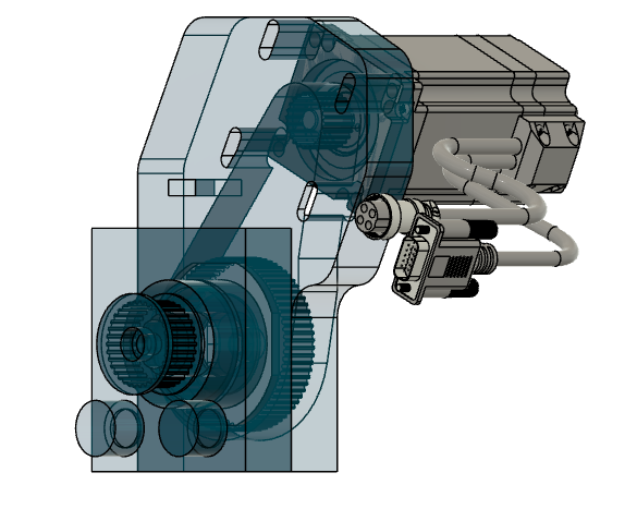
i think i have a good design starting point for this reduction set up for my Y axis. the X will be easy comparted to the Y axis i think. i think i even avoided losing axis travel and should work well if i can make in come to life  i think i will add a cover and rework my belt tension for the X axis into it but i think i have it compressed as much as i can work into this design,
Attachments:
The following user(s) said Thank You: tommylight
Please Log in or Create an account to join the conversation.
- spumco
- Offline
- Platinum Member
-

Less
More
- Posts: 1965
- Thank you received: 799
01 Oct 2024 18:08 #311128
by spumco
Replied by spumco on topic What do you really get for a $350 desk top engraver ?
Suggest making the cover a structural support that has outboard bearings for the pinion and belt idlers.
It need not be complicated - just a flat plate separated from the motor mount with standoffs and long bolts or threaded rods. Some flanged bearings pressed in and longer pinion & idler shafts will keep belt tension from flexing the shafts.
Tension the main drive belt at the fixed ends so the pinion can remain fixed in relation to the idlers.
Please Log in or Create an account to join the conversation.
- machinedude
-
 Topic Author
- Offline
- Platinum Member
-

Less
More
- Posts: 715
- Thank you received: 312
01 Oct 2024 19:42 #311129
by machinedude
Replied by machinedude on topic What do you really get for a $350 desk top engraver ?
I'm using two tapered roller bearings in opposing directions to anchor the pinion and take out any lateral movement. i don't think that part is going anywhere. I'm using pretty large bearings in that part everything is on a 1" shaft with Anti-rotation ends locked on with M8 screws that will also preload the bearings. it's hard to show everything with a screen grab 
The following user(s) said Thank You: spumco
Please Log in or Create an account to join the conversation.
- spumco
- Offline
- Platinum Member
-

Less
More
- Posts: 1965
- Thank you received: 799
01 Oct 2024 20:05 #311130
by spumco
Replied by spumco on topic What do you really get for a $350 desk top engraver ?
1" shaft with tapered rollers? Nice; disregard my last in that case.
Please Log in or Create an account to join the conversation.
- machinedude
-
 Topic Author
- Offline
- Platinum Member
-

Less
More
- Posts: 715
- Thank you received: 312
05 Oct 2024 18:31 #311363
by machinedude
Replied by machinedude on topic What do you really get for a $350 desk top engraver ?
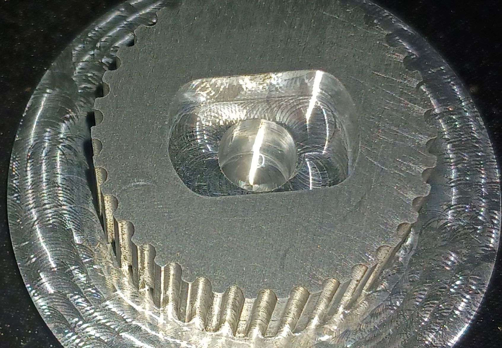
Well i had some time to test cutting an arc toothed pully. I was not even sure if i could or not with a 5/8 depth on this profile. i ended up buying a special extended reach 1/16 diameter end mill to try. it does work but it is not the fastest process for sure  i was not pushing anything very hard at all with the cost of this endmill being around $55 with tax and delivery. the bad news is i messed up with my model and offset my geometry in the wrong direction so this piece i made is no good, but the process works for sure.
Attachments:
The following user(s) said Thank You: tommylight
Please Log in or Create an account to join the conversation.
- machinedude
-
 Topic Author
- Offline
- Platinum Member
-

Less
More
- Posts: 715
- Thank you received: 312
07 Oct 2024 05:02 #311467
by machinedude
Replied by machinedude on topic What do you really get for a $350 desk top engraver ?
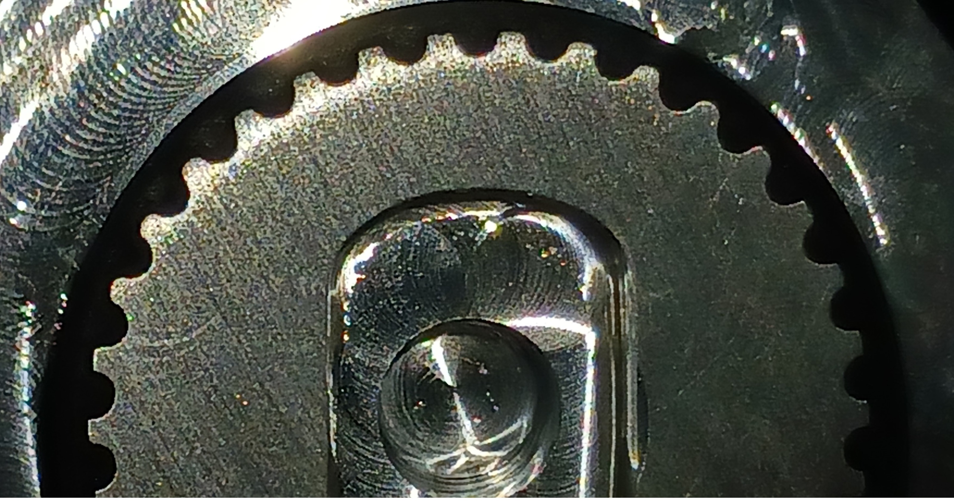
It took me 3 attempts, but the 3rd time was a charm  It would appear to me there is a fine line between getting just enough clearance and matching the belt profile exactly. too much clearance and you end up with backlash i would guess. but i think i have a close fit or at least as close as i can get and still have things work as they should.
Attachments:
The following user(s) said Thank You: tommylight
Please Log in or Create an account to join the conversation.
Time to create page: 0.231 seconds


