
- Posts: 62
- Thank you received: 30
ColorCNC Colorlight 5A-75E/5A-75B as FPGA controller board
- muvideo
- Offline
- Senior Member
-

Less
More
3 years 10 months ago #258601
by muvideo
basic setup.
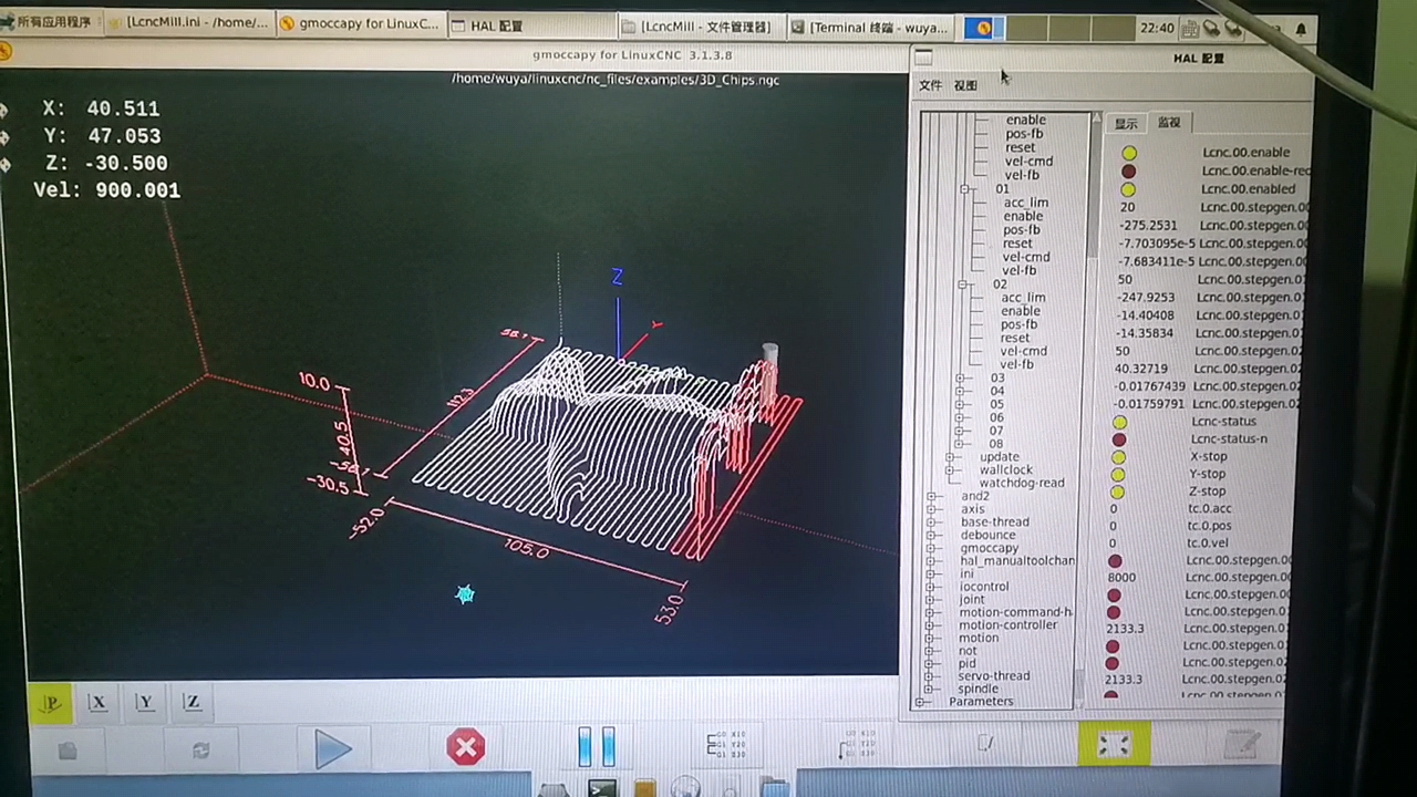
In your screen I'm unable to read the rightmost part of the pin names, so it's not easy to understand.
The boards seem enabled: Lcnc.00.enabled is true, so the communication is alive and the watchdog is healthy.
I suspect that a change I've made recently could be problematic: the timing for stepgen now is expressed in ns,
so you'll need at least 25 ns to have any signal out.
The default value for the driver was still wrongly expressed in us (values of 0.1), so if you don't define your own
timings with values higher than 25ns the stepgens could remain silent.
This behavior happens only if you have left the timings to the driver's default. The problem is fixed in latest commit.
the pins to check are Lcnc.00.stepgen-step_width Lcnc.00.stepgen-step_space Lcnc.00.stepgen-dir_width and finally
Lcnc.00.stepgen-setup_time, to be sure put them all at 1000.
Let me know.
Fabio
Replied by muvideo on topic ColorCNC Colorlight 5A-75E/5A-75B as FPGA controller board
Hi wuyatom, on what version of Lcnc are you working? I've made several changes lately that have changed some

My v7.1 board is not enabled
basic setup.
In your screen I'm unable to read the rightmost part of the pin names, so it's not easy to understand.
The boards seem enabled: Lcnc.00.enabled is true, so the communication is alive and the watchdog is healthy.
I suspect that a change I've made recently could be problematic: the timing for stepgen now is expressed in ns,
so you'll need at least 25 ns to have any signal out.
The default value for the driver was still wrongly expressed in us (values of 0.1), so if you don't define your own
timings with values higher than 25ns the stepgens could remain silent.
This behavior happens only if you have left the timings to the driver's default. The problem is fixed in latest commit.
the pins to check are Lcnc.00.stepgen-step_width Lcnc.00.stepgen-step_space Lcnc.00.stepgen-dir_width and finally
Lcnc.00.stepgen-setup_time, to be sure put them all at 1000.
Let me know.
Fabio
- wuyatom
- Offline
- Senior Member
-
Less
More
- Posts: 42
- Thank you received: 0
3 years 10 months ago #258662
by wuyatom
Replied by wuyatom on topic ColorCNC Colorlight 5A-75E/5A-75B as FPGA controller board
"ext_reset_in", 0, Pins("j4:0"),ensure that the RESET pin on the board is grounded,The grounding of my J4-1PIN is useless, and the measured voltage output is 0,The emergency stop button on the CNC interface pops up, and my 5A-75E J12-3PIN has a 5V voltage output
- wuyatom
- Offline
- Senior Member
-
Less
More
- Posts: 42
- Thank you received: 0
3 years 10 months ago #258665
by wuyatom

Now the latest version of LCNC is used, and I have modified the parts you asked me to modify
Replied by wuyatom on topic ColorCNC Colorlight 5A-75E/5A-75B as FPGA controller board
Now the latest version of LCNC is used, and I have modified the parts you asked me to modify
- muvideo
- Offline
- Senior Member
-
Less
More
- Posts: 62
- Thank you received: 30
3 years 10 months ago #258695
by muvideo
This should not prevent the board from enabling, since the connection of the fpga pin J4:0 to the ic driver should keep the pin to zero.
If you have already modded the board to access to fpga pins as inputs, and you are able to rebuild the configuration, you can move the reset pin where you have the inputs modifying the "J4:0" to on of the inputs you have. Keep in mind that in litex the first pin is zero.
About J12-3, if you are using the default configuration with my hal example, this should be the stepper driver output enable, so good news.
Is Lcnc.00.stepgen.0x.reset false?
I didnt get your last message, are you still having problems with the board?
Replied by muvideo on topic ColorCNC Colorlight 5A-75E/5A-75B as FPGA controller board
RESET is an input, so unfortunately if you dont make modifications to the board, the pins will be output only, and you will be unable to drive RESET from outside."ext_reset_in", 0, Pins("j4:0"),ensure that the RESET pin on the board is grounded,The grounding of my J4-1PIN is useless, and the measured voltage output is 0,The emergency stop button on the CNC interface pops up, and my 5A-75E J12-3PIN has a 5V voltage output
This should not prevent the board from enabling, since the connection of the fpga pin J4:0 to the ic driver should keep the pin to zero.
If you have already modded the board to access to fpga pins as inputs, and you are able to rebuild the configuration, you can move the reset pin where you have the inputs modifying the "J4:0" to on of the inputs you have. Keep in mind that in litex the first pin is zero.
About J12-3, if you are using the default configuration with my hal example, this should be the stepper driver output enable, so good news.
Is Lcnc.00.stepgen.0x.reset false?
I didnt get your last message, are you still having problems with the board?
- wuyatom
- Offline
- Senior Member
-
Less
More
- Posts: 42
- Thank you received: 0
3 years 10 months ago - 3 years 10 months ago #258700
by wuyatom
Replied by wuyatom on topic ColorCNC Colorlight 5A-75E/5A-75B as FPGA controller board
Lcnc.00.stepgen.0x.reset,show false。。Ask how to modify the circuit board, what needs to be modified?
Last edit: 3 years 10 months ago by wuyatom.
- muvideo
- Offline
- Senior Member
-
Less
More
- Posts: 62
- Thank you received: 30
3 years 10 months ago #258703
by muvideo
Replied by muvideo on topic ColorCNC Colorlight 5A-75E/5A-75B as FPGA controller board
Ok, so the board is enabled, the stepgens are enabled, the system should work. Is it working?
If not please describe the behavior you are seeing.
About the board modifications, the easiest way is to remove the drivers and connect bridges to the pins in order to route fpga pins directly to the headers.
But you are exposing the fpga to some risks, the voltages are 3.3V and there
is nothing saving your fpga from the slightly mistake.
I've breadboarded my interfaces with optocouplers for inputs.
As to what driver to remove, that depends on the board revision, there are some info earlier in this thread.
Moderators: PCW, jmelson
Time to create page: 0.426 seconds