7i96S card arrived what setup is recomended
- PCW
-

- Offline
- Moderator
-

Less
More
- Posts: 17917
- Thank you received: 5246
04 Sep 2022 22:57 #251191
by PCW
Replied by PCW on topic 7i96S card arrived what setup is recomended
OK if there is a flyback diode on the contactor coil, the noise is likely coming
from the contact side of the contactor
If you cannot isolate the control wiring from the power wiring you
may need to either shield the control wiring or add arc suppression
to the contactor contacts (commonly a R/C snubber is used here)
from the contact side of the contactor
If you cannot isolate the control wiring from the power wiring you
may need to either shield the control wiring or add arc suppression
to the contactor contacts (commonly a R/C snubber is used here)
The following user(s) said Thank You: xenon-alien
Please Log in or Create an account to join the conversation.
- xenon-alien
-

- Offline
- Premium Member
-

Less
More
- Posts: 157
- Thank you received: 4
05 Sep 2022 06:29 #251205
by xenon-alien
But in my case the flyback diode and the coil are not working, because I switching ON/OFF the contactor by my hand (without 24v power supply) and the input LEDs are blinking.
I will try to shield it and somehow separate them.
The arc suppression looks like this? What resistance resistor and what capacity capacitor should I use? (if the manipulation wont be success)

Replied by xenon-alien on topic 7i96S card arrived what setup is recomended
Thanks for your advices!OK if there is a flyback diode on the contactor coil, the noise is likely coming
from the contact side of the contactor
If you cannot isolate the control wiring from the power wiring you
may need to either shield the control wiring or add arc suppression
to the contactor contacts (commonly a R/C snubber is used here)
But in my case the flyback diode and the coil are not working, because I switching ON/OFF the contactor by my hand (without 24v power supply) and the input LEDs are blinking.
I will try to shield it and somehow separate them.
The arc suppression looks like this? What resistance resistor and what capacity capacitor should I use? (if the manipulation wont be success)
Attachments:
Please Log in or Create an account to join the conversation.
- xenon-alien
-
- Offline
- Premium Member
-
Less
More
- Posts: 157
- Thank you received: 4
05 Sep 2022 06:30 #251206
by xenon-alien
But in my case the flyback diode and the coil are not working, because I switching ON/OFF the contactor by my hand (without 24v power supply) and the input LEDs are blinking.
I will try to shield it and somehow separate them.
The arc suppression looks like this? What resistance resistor and what capacity capacitor should I use? (if the manipulation wont be success)
We also bought 3 ph SSR...
Replied by xenon-alien on topic 7i96S card arrived what setup is recomended
Thanks for your advices!OK if there is a flyback diode on the contactor coil, the noise is likely coming
from the contact side of the contactor
If you cannot isolate the control wiring from the power wiring you
may need to either shield the control wiring or add arc suppression
to the contactor contacts (commonly a R/C snubber is used here)
But in my case the flyback diode and the coil are not working, because I switching ON/OFF the contactor by my hand (without 24v power supply) and the input LEDs are blinking.
I will try to shield it and somehow separate them.
The arc suppression looks like this? What resistance resistor and what capacity capacitor should I use? (if the manipulation wont be success)
We also bought 3 ph SSR...
Please Log in or Create an account to join the conversation.
- xenon-alien
-
- Offline
- Premium Member
-
Less
More
- Posts: 157
- Thank you received: 4
05 Sep 2022 07:18 - 05 Sep 2022 07:19 #251208
by xenon-alien
Replied by xenon-alien on topic 7i96S card arrived what setup is recomended
Here are the conf files.2) The Spindle Close-Loop
There is a simple 3 ph AC motor and inverter. They are connected and turning the Spindle CW/CCW.
The Lathe has 3 speeds. On the first speed when I command to turn 200 rpm (almost 1:1 ratio), it's turning with 275 ±2rpm.
The scaling not correct yet. I will do it soon.
Is it possible to use the Close-Loop to use all speeds automatically, without using any other hal component.
(the lathe config will upload on monday.)
Attachments:
Last edit: 05 Sep 2022 07:19 by xenon-alien.
Please Log in or Create an account to join the conversation.
- xenon-alien
-
- Offline
- Premium Member
-
Less
More
- Posts: 157
- Thank you received: 4
05 Sep 2022 09:03 - 05 Sep 2022 09:39 #251218
by xenon-alien
Replied by xenon-alien on topic 7i96S card arrived what setup is recomended
We received 3 ph SSR (i think they are used) - D53TP50D Relay; SSR; Zero-Switching; Cur-Rtg 50A; Ctrl-V 3-32DC; Vol-Rtg 48-530AC; Pnl-Mnt.
But not really understand, are they OK?
Without load I see 220V.
When I plug a load (soldering iron) I see 114v. (but the load not turns ON) With a 25W lamp the voltage is 0v.
When I turn on the SSR with 24v I see 220v and the load is turns on. (With a 25W lamp the voltage is 220v.)
So the question is, Can I use them for Turret CW/CCW switching 2 wires?
The output will look like (A2toA2) (B2toC2) (C2toB2) and goes to the turret 3 ph AC motor.
Wont it blow up (with those measurements)?
Last edit: 05 Sep 2022 09:39 by xenon-alien.
Please Log in or Create an account to join the conversation.
- xenon-alien
-
- Offline
- Premium Member
-
Less
More
- Posts: 157
- Thank you received: 4
07 Sep 2022 09:16 #251393
by xenon-alien
setp hm2_7i96s.0.pwmgen.00.scale [SPINDLE_0]MAX_RPM (in the hal)
I have 275 ±2rpm, when I command to turn 200 rpm.
But when I change the MAX_RPM = 2800 (2700) It should change the pwm.scale, but no effect.
Then I command to turn 300 rpm I have 310 ±2rpm
Then I command to turn 400 rpm I have 425 ±2rpm
So I'm not really understand how to use the 7i96s functionality...
Or I have problems with the 10v output from the VFD - 10.67v
200 rpm (Enc 270) - 0.75v
300 rpm (Enc 310) - 1.13v
400 rpm (Enc 420) - 1.51v
500 rpm (Enc 530) - 1.89v
Encoder showing correct numbers (270 rpm), I've tested it with an optical tachometer (270± rpm on the spindle).
Replied by xenon-alien on topic 7i96S card arrived what setup is recomended
Hello.In the MAX_RPM = 2900 (in the ini - the motor speed, but there are some ratio)
2) The Spindle Close-LoopThere is a simple 3 ph AC motor and inverter. They are connected and turning the Spindle CW/CCW.The Lathe has 3 speeds. On the first speed when I command to turn 200 rpm (almost 1:1 ratio), it's turning with 275 ±2rpm.The scaling not correct yet. I will do it soon.Is it possible to use the Close-Loop to use all speeds automatically, without using any other hal component.(the lathe config will upload on monday.) Here are the conf files.
setp hm2_7i96s.0.pwmgen.00.scale [SPINDLE_0]MAX_RPM (in the hal)
I have 275 ±2rpm, when I command to turn 200 rpm.
But when I change the MAX_RPM = 2800 (2700) It should change the pwm.scale, but no effect.
Then I command to turn 300 rpm I have 310 ±2rpm
Then I command to turn 400 rpm I have 425 ±2rpm
So I'm not really understand how to use the 7i96s functionality...
Or I have problems with the 10v output from the VFD - 10.67v
200 rpm (Enc 270) - 0.75v
300 rpm (Enc 310) - 1.13v
400 rpm (Enc 420) - 1.51v
500 rpm (Enc 530) - 1.89v
Encoder showing correct numbers (270 rpm), I've tested it with an optical tachometer (270± rpm on the spindle).
Please Log in or Create an account to join the conversation.
- PCW
-
- Offline
- Moderator
-
Less
More
- Posts: 17917
- Thank you received: 5246
07 Sep 2022 15:28 #251411
by PCW
Replied by PCW on topic 7i96S card arrived what setup is recomended
The voltages look scaled correctly (200/2900 *10.67 = 0.735862069V so 0.75V is very close)
but its likely the VFD is not terribly linear at low speeds. MAX_RPM will change the PWM scaling
but if you need it to be more linear you may need to use some compensation like the lincurve
component (or run closed loop)
but its likely the VFD is not terribly linear at low speeds. MAX_RPM will change the PWM scaling
but if you need it to be more linear you may need to use some compensation like the lincurve
component (or run closed loop)
The following user(s) said Thank You: xenon-alien
Please Log in or Create an account to join the conversation.
- xenon-alien
-
- Offline
- Premium Member
-
Less
More
- Posts: 157
- Thank you received: 4
07 Sep 2022 16:00 #251415
by xenon-alien
About lincurve component I will read.
Better is the closed loop, but i have no idea, how to make it work. (We have 3 speeds, but i think we will use only one)
Can you help me out with the closed loop?
Replied by xenon-alien on topic 7i96S card arrived what setup is recomended
Tomorrow I will try to change the scale from 2900 to 2000 to see some difference. (if it will be)The voltages look scaled correctly (200/2900 *10.67 = 0.735862069V so 0.75V is very close)
but its likely the VFD is not terribly linear at low speeds. MAX_RPM will change the PWM scaling
but if you need it to be more linear you may need to use some compensation like the lincurve
component (or run closed loop)
About lincurve component I will read.
Better is the closed loop, but i have no idea, how to make it work. (We have 3 speeds, but i think we will use only one)
Can you help me out with the closed loop?
Please Log in or Create an account to join the conversation.
- andypugh
-

- Offline
- Moderator
-
Less
More
- Posts: 19861
- Thank you received: 4636
17 Sep 2022 09:27 #252152
by andypugh
I found this wiki.linuxcnc.org/cgi-bin/wiki.pl?Closed...pindle_Speed_Control
But it is rather outdated, as it has all the old spindle pins (motion.spindle rather than spindle.0. A global change to the latter should help). Also it is using a software encoder, rather than a Mesa one.
Replied by andypugh on topic 7i96S card arrived what setup is recomended
[/quote]Can you help me out with the closed loop?
I found this wiki.linuxcnc.org/cgi-bin/wiki.pl?Closed...pindle_Speed_Control
But it is rather outdated, as it has all the old spindle pins (motion.spindle rather than spindle.0. A global change to the latter should help). Also it is using a software encoder, rather than a Mesa one.
The following user(s) said Thank You: xenon-alien
Please Log in or Create an account to join the conversation.
- xenon-alien
-
- Offline
- Premium Member
-
Less
More
- Posts: 157
- Thank you received: 4
26 Dec 2022 12:44 #260320
by xenon-alien
Replied by xenon-alien on topic 7i96S card arrived what setup is recomended
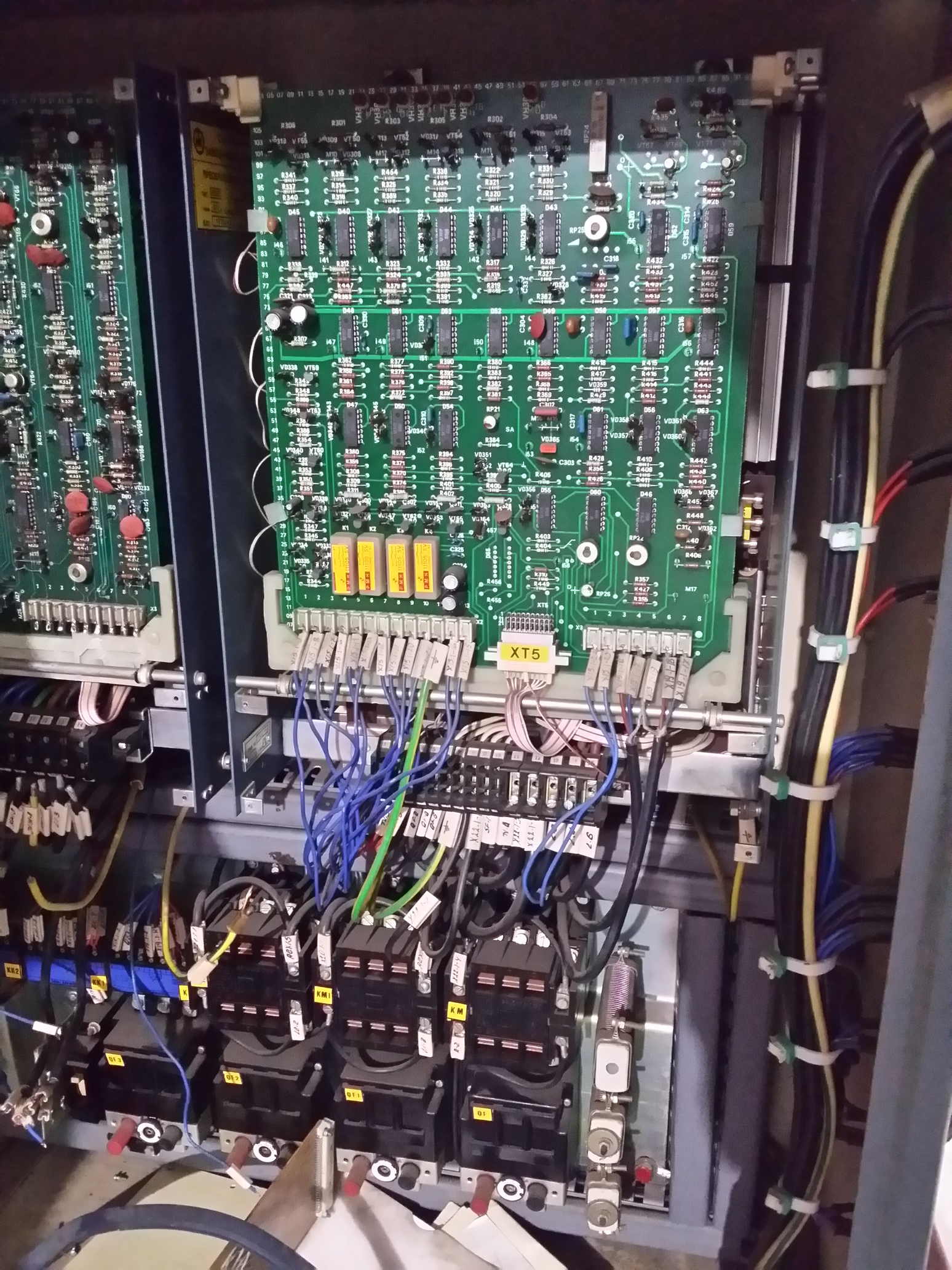
Hello!
How much voltage can handle the analog output?
I saw min. 5v max. 18v in the manual.
We have an old lathe with ±15v output from the driver.
Can we use this voltage with scaling in the setup to have ±10v output?
The ±15v wont damage the analog I/O port?
How much voltage can handle the analog output?
I saw min. 5v max. 18v in the manual.
We have an old lathe with ±15v output from the driver.
Can we use this voltage with scaling in the setup to have ±10v output?
The ±15v wont damage the analog I/O port?
Attachments:
Please Log in or Create an account to join the conversation.
Moderators: PCW, jmelson
Time to create page: 0.226 seconds