Search Results (Searched for: )
- hitchhiker
- hitchhiker
31 Jul 2026 20:27
Replied by hitchhiker on topic PUMA 200 Robotarm and some Hal/INI issues
PUMA 200 Robotarm and some Hal/INI issues
Category: Advanced Configuration
- NWE

31 Jul 2026 20:21
Replied by NWE on topic PUMA 200 Robotarm and some Hal/INI issues
PUMA 200 Robotarm and some Hal/INI issues
Category: Advanced Configuration
- leexi
- leexi
31 Jul 2026 20:10 - Yesterday 08:16
Replied by leexi on topic Chinise mesa clone vs Original vs Ethercat
Chinise mesa clone vs Original vs Ethercat
Category: Driver Boards
- Todd Zuercher

31 Jul 2026 20:05
Replied by Todd Zuercher on topic Highlighted gcode doesn't follow current position.
Highlighted gcode doesn't follow current position.
Category: Gmoccapy
- hitchhiker
- hitchhiker
31 Jul 2026 19:10
Replied by hitchhiker on topic PUMA 200 Robotarm and some Hal/INI issues
PUMA 200 Robotarm and some Hal/INI issues
Category: Advanced Configuration
") thanks
thanks - MaHa
- MaHa
31 Jul 2026 19:07
Replied by MaHa on topic Highlighted gcode doesn't follow current position.
Highlighted gcode doesn't follow current position.
Category: Gmoccapy
- cmorley
- cmorley
31 Jul 2026 18:17
- TheTinkeringMechanic1
- TheTinkeringMechanic1
31 Jul 2026 18:10 - 31 Jul 2026 18:12
Replied by TheTinkeringMechanic1 on topic Highlighted gcode doesn't follow current position.
Highlighted gcode doesn't follow current position.
Category: Gmoccapy
- meister
- meister
31 Jul 2026 17:36 - 31 Jul 2026 18:49
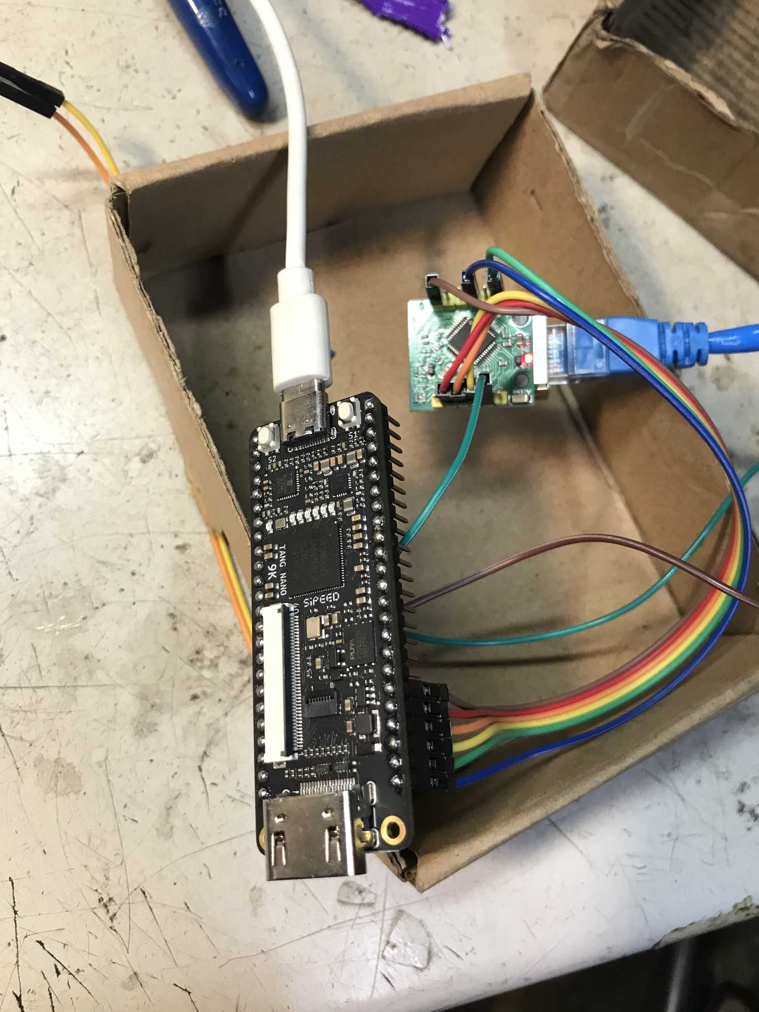
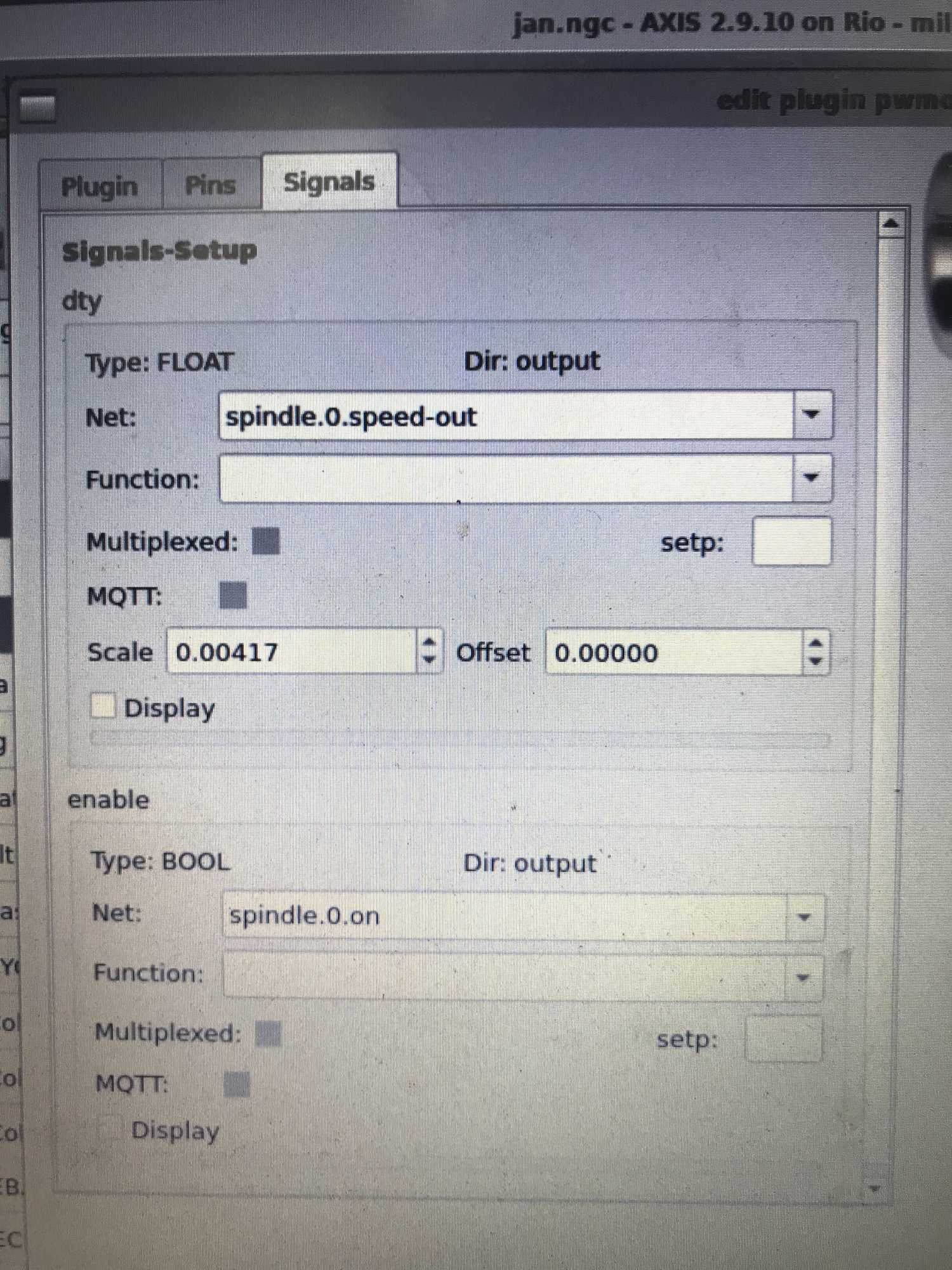
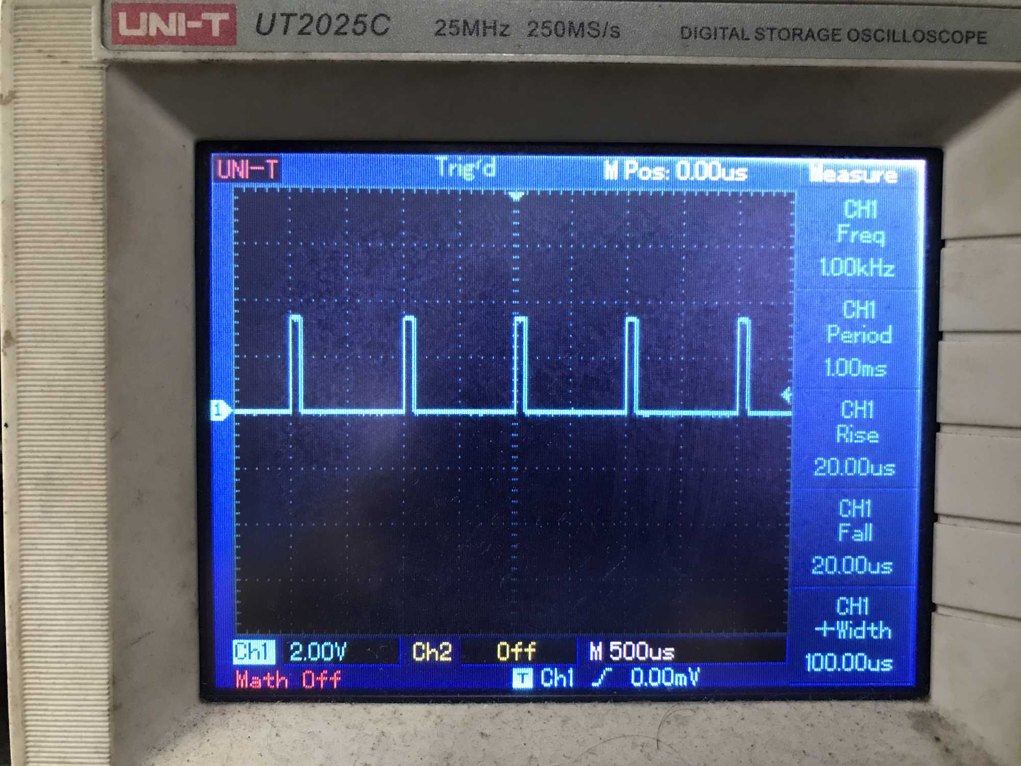
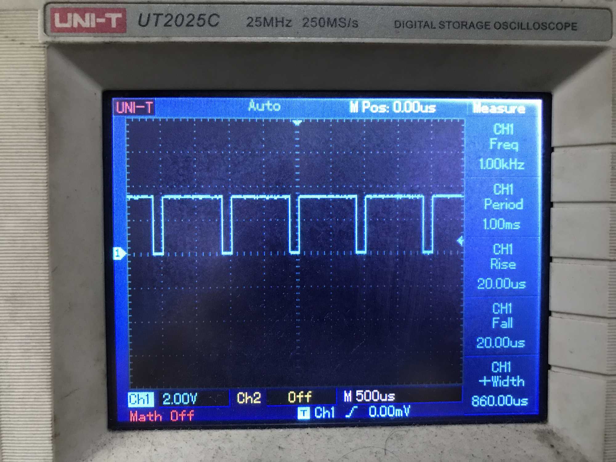
Replied by meister on topic LinuxCNC-RIO - RealtimeIO for LinuxCNC based on FPGA (ICE40 / ECP5)
LinuxCNC-RIO - RealtimeIO for LinuxCNC based on FPGA (ICE40 / ECP5)
Category: Computers and Hardware
- Todd Zuercher
31 Jul 2026 17:14
- tuxcnc
- tuxcnc
31 Jul 2026 17:07
- tuxcnc
- tuxcnc
31 Jul 2026 16:41
Replied by tuxcnc on topic LinuxCNC-RIO - RealtimeIO for LinuxCNC based on FPGA (ICE40 / ECP5)
LinuxCNC-RIO - RealtimeIO for LinuxCNC based on FPGA (ICE40 / ECP5)
Category: Computers and Hardware
- Holzwurm56
- Holzwurm56
31 Jul 2026 15:40
Replied by Holzwurm56 on topic Help Controller for a Lathe ?
Help Controller for a Lathe ?
Category: CNC Machines
- viewsat
- viewsat
31 Jul 2026 15:34 - 31 Jul 2026 16:03
Replied by viewsat on topic LinuxCNC-RIO - RealtimeIO for LinuxCNC based on FPGA (ICE40 / ECP5)
LinuxCNC-RIO - RealtimeIO for LinuxCNC based on FPGA (ICE40 / ECP5)
Category: Computers and Hardware
- tommylight

31 Jul 2026 14:54
Time to create page: 0.886 seconds