Advanced Search

Search Results (Searched for: )

  • PCW
  • PCW's Avatar
25 Jul 2025 15:51
Replied by PCW on topic Connecting my 7i96s to the VFD

Connecting my 7i96s to the VFD

Category: Driver Boards

For direction, assuming S1 is FWD and S2 is REV:

S1 --> OUT4A 
OUT4B --> COM

S2 --> OUT5A 
OUT5B --> COM
 
  • Waggi
  • Waggi
25 Jul 2025 15:32

Vorschau Berechnung der Grenzwerte passt nicht wenn M6 enthalten

Category: Deutsch

Sorry habe eine Frage gestellt und mich lang nicht mehr gemeldet. Da kam was privates dazwischen und somit musste Linuxcnc warten.
Vieleicht erkläre ich nochmals etwas anders was meine eigentliche Frage ist. Außerdem habe ich nicht alles gesagt was wichtig ist. Ist mir aber beim ersten Schreiben nicht aufgefallen.Ich habe den M6 geremappt (schreibt man das so?) Ich habe die Dynamische Werkzeug-Längenvermessung von Talla83 eingebaut. Diese funktioniert auch.Kurz der Ablauf:
Man legt ein beliebiges Werkzeug ein
Man startet einen Toolwechsel  z. B. T2 M6
Anschließend nullt man das Werkzeug auf die Oberfläche
Beim nächsten Werkzeugwechsel wird der Tooloffset TLO wieder so berechnet das die Spitze des Werkzeugs auf der Oberfläche aufliegtMein Problem ist nun das der Werkzeugwechsel mit in die Berechnung der Grenzwerte mit einbezogen wird. Das hätte ich gerne ausgenommen. Mir ist schon klar dass wenn ich ein super kurzes Werkzeug nehme das ich dann die Z-Achse evtl nicht mehr tief genug fahren kann und umgekehrt wenn ich ein besonders langes Werkzeug nehme  dann evtl die Z-Aches nicht hoch genug fahren kann. Aber ganz ohne mitdenken geht es beim fräsen ohnehin nicht.Nun 2 Beispiele. Ich würde gerne eine Berechnug wie in Beispiel 1 haben auch wenn wein Werkzeugwechsel vorkommt.Beispiel 1Starte ich ein Fräsprogramm bei dem beim Start bereits das passende Werkzeug in der Spindel ist, dann beschränkt sich die Berechnung der Grenzwerte sozusagen an der äußeren Kontur des Objetes. Beispiel: Ich fräse ein Quadat mit einer Kantenlänge von 10mm welches mit der linken unteren Ecke auf X0, Y0 Z0 liegt  mit einem 4mm Fräser aus. Dann sind die Grenzwerte in X -2 und X12, gleiches in Y.
Liegt die eingestellte Sicherheitshöhe bei 15mm und die Frästiefe bei -2mm sind die Grenzwerte in Z-Richtung Z-2mm und Z15mm.

Beispiel 2Habe ich aber noch kein passendes Werkzeug in der Spindel, werden die Wege zu dem Platz an dem ich das Werkezug wechsle bzw an dem das Werkzeug vermesse mit beachtet. So ist z. B. X plötzlich -450mm. Bei den Z-Werten passt gar nichts mehr, die sind meist außerhalb Bauraum. Ich vermute das liegt daran das LCNC bei den Befehlen die antasten (G38.2) nicht weiß wie weit sie wirklich fahren.

Wenn man davon ausgeht das der Befehl T2 M6 wenn man ihn in der Befehlszeile ( MDI) eingibt an sich funktioniert und nie den Bauraum verläßt, sollte er doch eigentlich nicht dazu führen können, wenn er in einem Fräsprogramm auftaucht, dass dann die Z-Achse die Grenzwerte überschreitet.Die LCNC-Version ist 2.93Anbei ein Bild wenn bereits das richtige Tool vorhanden ist und ein Bild wenn noch ein anderes Tool geladen ist.Und die Routine die die dynamischen Werkzeugwechsel macht.
  • scsmith1451
  • scsmith1451
25 Jul 2025 14:05
Replied by scsmith1451 on topic Set program zero using XY positioning laser

Set program zero using XY positioning laser

Category: Advanced Configuration

In my process to integrate the X/Y crosshair laser into my test machine configuration, searching the forum I read that gladevcp had a toggle button that sounded like it would work for controlling the laser on/off. Modifying my configuration with pncconf I replace my pyvcp with gladevcp using the default sample with just the spindle speed bar and spindle at speed LED.

Starting LCNC the machine an error was generated indicating that the n_rows property for the gladevcp was not valid. A little more forum searching if found the GTKbugfix.tar.gz archive and following the forum guidance copied the files to their correct location.

Upon restart of LCNC, the gladevcp panel displayed correctly. Excited, I decided to include the sample's Zero X/Y/Z/A buttons via pncconf.

Upon restart the following error was spit out:

ERROR: function 'abs.spindle' not found

Checking the HAL file it appears to be caused by this line:

addf abs.spindle servo-thread

Figuring that this was somehow connected with adding the ZERO buttons, I removed the buttons via pncconf and restarted.

Now LCNC generates the error every time it is started.

I'm befuddled and do not know where to go from here. Anyone have any ideas?

Kind Regards
  • PCW
  • PCW's Avatar
25 Jul 2025 13:43 - 25 Jul 2025 16:03

threading - spindle encoder synchonization issues

Category: Turning

Yes, I think that there's a misunderstanding of how differential signaling works here.

The high input sensitivity allows detection of small differential signals but the differential noise
immunity is equal to the differential signal level from the source
.  Because it is a differential
receiver designed for a high noise environment, it has a wide common mode range (-7 to +12V)
meaning it can detect small differential signals (> 200 mv) accurately even with -7 to +12V of
common mode noise. This is why RS-422 signaling is used for encoders.

If the 7I76 single ended setting works better than the differential setting on supposedly
differential signals it suggests that there is some hardware issue.

I would check first that you have true differential signals from the encoder.

To do this, use a voltmeter across the differential pairs (A,/A B,/B IDX,/IDX)
and measure the voltage as you jog the encoder a bit to get both states.

One state should read a positive voltage and the other a negative voltage.
in no case should the absolute differential voltage be less than 2V.
 
  • ChironFZ16
  • ChironFZ16's Avatar
25 Jul 2025 13:05 - 25 Jul 2025 13:08
Problem mit xhc-whb04b-6 was created by ChironFZ16

Problem mit xhc-whb04b-6

Category: Deutsch

Hallo zusammen
Ich habe einige Probleme mit dem Teil. in Simulations modus startet das Ding nicht und in normalen Modus habe ich keinen Kontakt. Der Treiber startet , hatt aber einen Konflikt mit GLADE-Dateien

Starting HAL User Interface program: halui
linuxcnc TPMOD=tpmod HOMEMOD=homemod EMCMOT=motmod
Found file(REL): ./core_sim.hal
Found file(REL): ./spindle_sim.hal
Found file(REL): ./simulated_home.hal
Found file(REL): ./whb04b.hal
Shutting down and cleaning up LinuxCNC...
Removing HAL_LIB, RTAPI, and Real Time OS modules
Removing NML shared memory segments

Debug file information:
Note: Using POSIX realtime

failed to claim interface
scale: already exists
./whb04b.hal:20: waitpid failed /usr/bin/rtapi_app scale
./whb04b.hal:20: /usr/bin/rtapi_app exited without becoming ready
./whb04b.hal:20: insmod for scale failed, returned -1
13130
Stopping realtime threads
Unloading hal components
Note: Using POSIX realtime


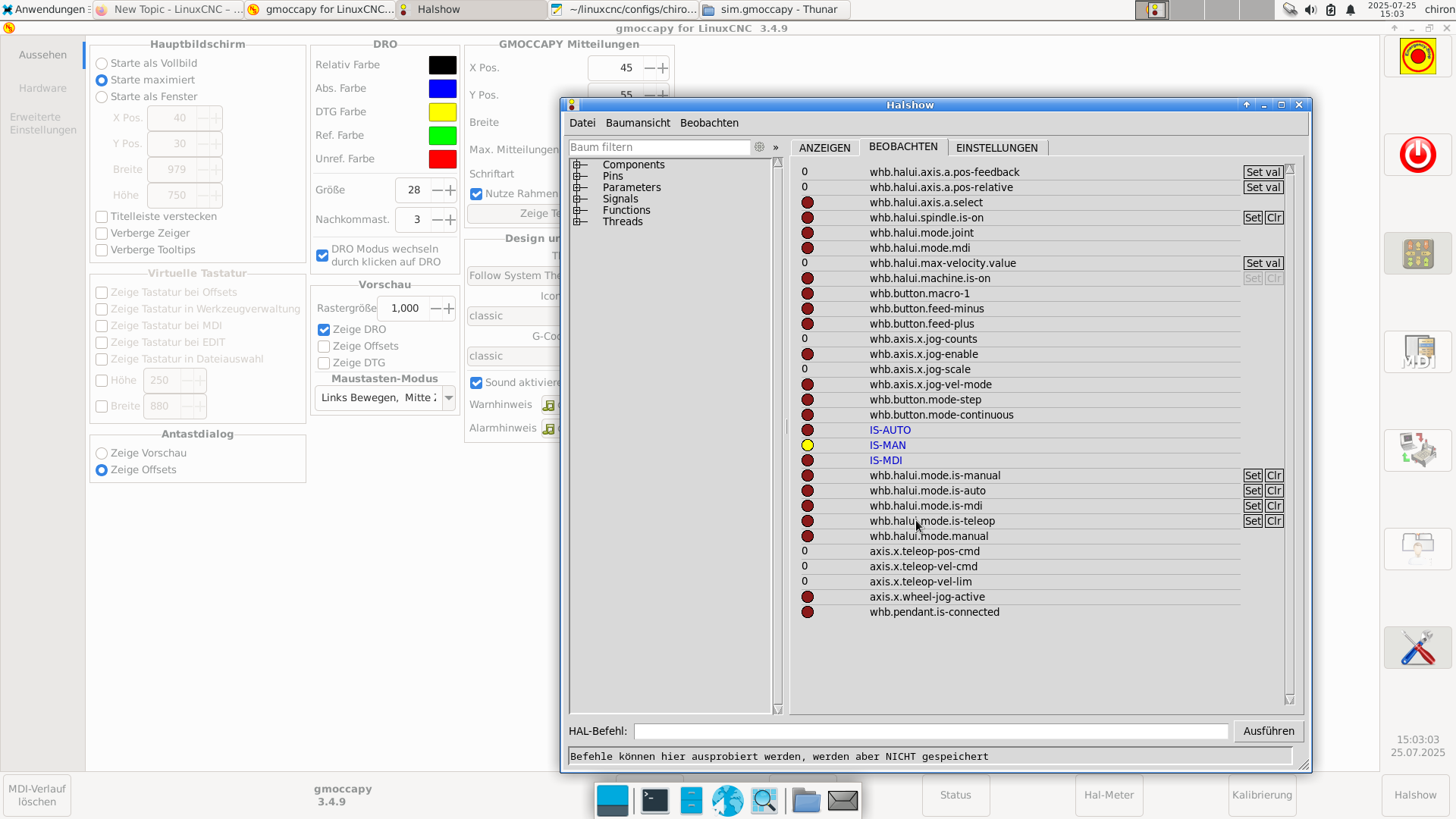
Das whb.pendant.is-connected sollte doch gelb aufleuchten, oder ?
  • tommylight
  • tommylight's Avatar
25 Jul 2025 12:02
Replied by tommylight on topic How to install kernel patch? (Moschip 9900)

How to install kernel patch? (Moschip 9900)

Category: Installing LinuxCNC

What power supply is powering the drive?
2 years back i had some really bad power supplies that caused a lot of noise, so i did the humane thing and showed them the trash bin. :)
  • Todd Zuercher
  • Todd Zuercher's Avatar
25 Jul 2025 11:59
Replied by Todd Zuercher on topic Problem G-code?

Problem G-code?

Category: G&M Codes

I'm sorry I don't understand what the point of checking to see if #_task> is equal to 0 in my sub program that is intended to end the program.  And maybe that isn't the best way to do that.  I basically have two branches, the surfacing program can end either at the front or back of the machine depending on where it runs out of space.  Then it needs to raise the spindles, turn them off, and end the program.  Maybe it would have been better to end it like this.
(Table Surfacing)
(No Fences Installed While Surfacing !!!)
(Todd Zuercher 07/24/2025)
#1=[60/25.4] (Tool Diameter 60mm)
#2=[#1*0.45] (Starting point)
#3=500 (Surfacing Feed Rate)
#4=50 (Plunge Feed Rate)
#5=35.0 (X extent)
#6=125.0 (Y extent)
#7=0.95 (Step over %/100)
(begin preamble)
G17 G54 G40 G49 G80 G90
G20
G53 G0 Z0 W0
M6T1
M3 S9000
F#4
G0 X#2 Y0
G0 Z0.25 W0.25
M0
G1 Z0.0 W0.0
o100 do
  G1 X#2 F#3
  G1 Y#6
  #2=[#2+#1*#7]
    o110 if [#2 GT #5]
      o100 break
    o110 else
      G1 X#2
      G1 Y0
    o110 endif
  #2=[#2+#1*#7]
o100 while [#2 LT #5]
G53 G0 Z0 W0
M5
M2
  • tommylight
  • tommylight's Avatar
25 Jul 2025 11:58
Replied by tommylight on topic Connecting my 7i96s to the VFD

Connecting my 7i96s to the VFD

Category: Driver Boards

Yes, that is correct.
  • tommylight
  • tommylight's Avatar
25 Jul 2025 11:57
Replied by tommylight on topic Problem G-code?

Problem G-code?

Category: G&M Codes

Axis GUI?
Did you accidentally press the 0 on the keyboard? That would set the feed rate to 0 and would do exactly as you describe, namely start and go to the first cut and stop there waiting.
  • dunnitagain
  • dunnitagain
25 Jul 2025 11:38

Linuxcnc 2.4.5 with Ubuntu 10.04, Correct file path or structure ?

Category: General LinuxCNC Questions

I will try that tommorrow , There is no real Identification on the PC, Small Black Box , Has a Motherboard and a Hard drive only.
  • Todd Zuercher
  • Todd Zuercher's Avatar
25 Jul 2025 10:49
Replied by Todd Zuercher on topic Problem G-code?

Problem G-code?

Category: G&M Codes

It wasn't spindle at speed, I had checked that first thing. It wasn't the M0 pause, I had tried running it with that line deleted with the same result. Starting the program rhe machine would raise the spindles, start the spindles, move to the starting point, lower the spindles down to 0.25, and pause, At this point clicking the pause button or pressing the next line buttons would have no effect. I tried debugging the parameter that was setting the feed rate before Line 20, and it was what it was supposed to be. I tried deleting the parameter for the feed and expicitly setting the F term with the real feed number, no effect. Deleting the M0 only changed that the pause button on the menu bar wouldn't toggle on, but the machine still would not proceed beyond line 20.

I still don't know what the real problem was, but I restarted the Linuxcnc from the command line to try to see if there were any messages there, and then it ran fine. weird
  • Gautham
  • Gautham
25 Jul 2025 10:43
Connecting my 7i96s to the VFD was created by Gautham

Connecting my 7i96s to the VFD

Category: Driver Boards

Hi Everyone,

I have never setup a CNC machine before, so while I found many other people's posts on similar topics helpful, I'm still not confident enough to try it myself without asking someone if I have it correct. I have a 7i96s board, and I can see that the TB2 PINs 22,23,24 are as follows.

22 - SPINDLE-
23 - SPINDLE OUT
24 - SPINDLE+

And the below image is my VFD's pinout


From this I gather the following

22 - SPINDLE- to COM
23 - SPINDLE OUT to AI1
24 - SPINDLE+ to +10v

Is this correct? I also wanted to know how to control the direction. Thank you for being so helpful.

Gautham

 
  • dm17ry
  • dm17ry's Avatar
25 Jul 2025 09:13

threading - spindle encoder synchonization issues

Category: Turning

In this mode it uses a Renesas ISL32173 chip to take in the differential signal through what amounts to a comparator and output a logical signal to some counter in the FPGA. The issue is that the chip is designed to be really sensitive and a differential signal over 0.2V is considered high. That is nuts on a signal that is 3.3V or 5V differential.

200mV diff voltage threshold comes from the EIA-422 standard. i believe every compliant receiver IC does the same. nevertheless, usually they perform nicely in pretty harsh noise environment. i suspect your "backpack" may be a problem, not the 7i76
  • andypugh
  • andypugh's Avatar
25 Jul 2025 08:57

Simulating a hm2_eth driver (e.g. mesacard 7i76e)

Category: Driver Boards

You could consider adding this to the Wiki too.

wiki.linuxcnc.org/cgi-bin/wiki.pl?ContributedComponents

Here is how to edit a wiki page:
wiki.linuxcnc.org/cgi-bin/wiki.pl?BasicSteps

FWIW the penguin is called "Chips" (though I don't recall if he capitalises his name)
  • ziggi
  • ziggi's Avatar
25 Jul 2025 05:30

Troubles to get started with SD240 Retrofit

Category: Turning

So I found the AXIS Gui document and if I apply the pins described there to your MPG code, it should be about this

# Set jog-vel-mode to false (joint will move exactly jog-scale units for each count)
setp joint.0.jog-vel-mode 0
setp joint.1.jog-vel-mode 0
setp axis.x.jog-vel-mode 0
setp axis.z.jog-vel-mode 0

# Set jog scale 
setp mpg-scale 1.0
net  mpg-scale joint.0.jog-scale axis.x.jog-scale <= halui.axis.selected.increment
net  mpg-scale joint.1.jog-scale axis.z.jog-scale <= halui.axis.selected.increment

# Joint selection (enable only one at a time)
net mpg-select-x joint.0.jog-enable axis.x.jog-enable <= halui.axis.selected.0
net mpg-select-z joint.1.jog-enable axis.z.jog-enable <= halui.axis.selected.1

# Connect encoder counts to all joints (only enabled one will move)
net mpg-counts  <=  hm2_7i80.0.encoder.03.count
net mpg=counts  joint.0.jog-counts  axis.x.jog-counts
net mpg-counts  joint.1.jog-counts  axis.z.jog-counts

Is this how it could work to use the AXIS-GUI pins instead of an axis and a increment selctor switches?

Sigi
Displaying 736 - 750 out of 24346 results.
Time to create page: 0.229 seconds
Powered by Kunena Forum