Search Results (Searched for: )
- TheTinkeringMechanic1
- TheTinkeringMechanic1
03 Aug 2025 15:54
Replied by TheTinkeringMechanic1 on topic Spindle speed?
Spindle speed?
Category: Basic Configuration
- --Matt--
- --Matt--
03 Aug 2025 15:51
Replied by --Matt-- on topic Surfacemap Z compensation with Probe Basic
Surfacemap Z compensation with Probe Basic
Category: QtPyVCP
- my1987toyota

03 Aug 2025 15:19 - 03 Aug 2025 16:00
Replied by my1987toyota on topic Voron Life , for anyone going into 3D printing !
Voron Life , for anyone going into 3D printing !
Category: Additive Manufacturing
- GDTH

03 Aug 2025 15:00
Replied by GDTH on topic Mesaflash is not able to find 5i25
Mesaflash is not able to find 5i25
Category: Driver Boards
- TheTinkeringMechanic1
- TheTinkeringMechanic1
03 Aug 2025 14:52
Replied by TheTinkeringMechanic1 on topic Spindle speed?
Spindle speed?
Category: Basic Configuration
- AkkiSan
- AkkiSan
03 Aug 2025 14:49 - 03 Aug 2025 14:55
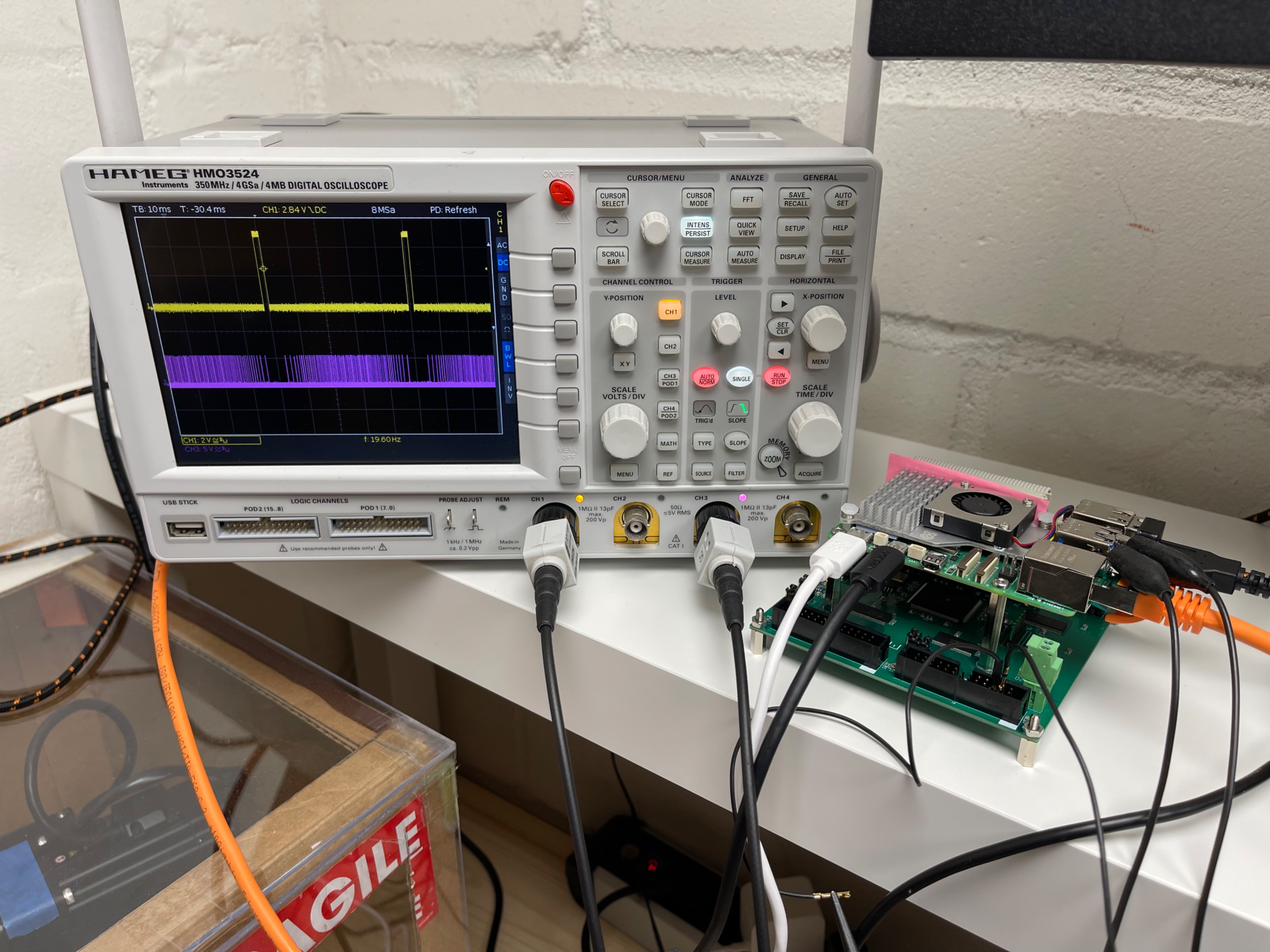
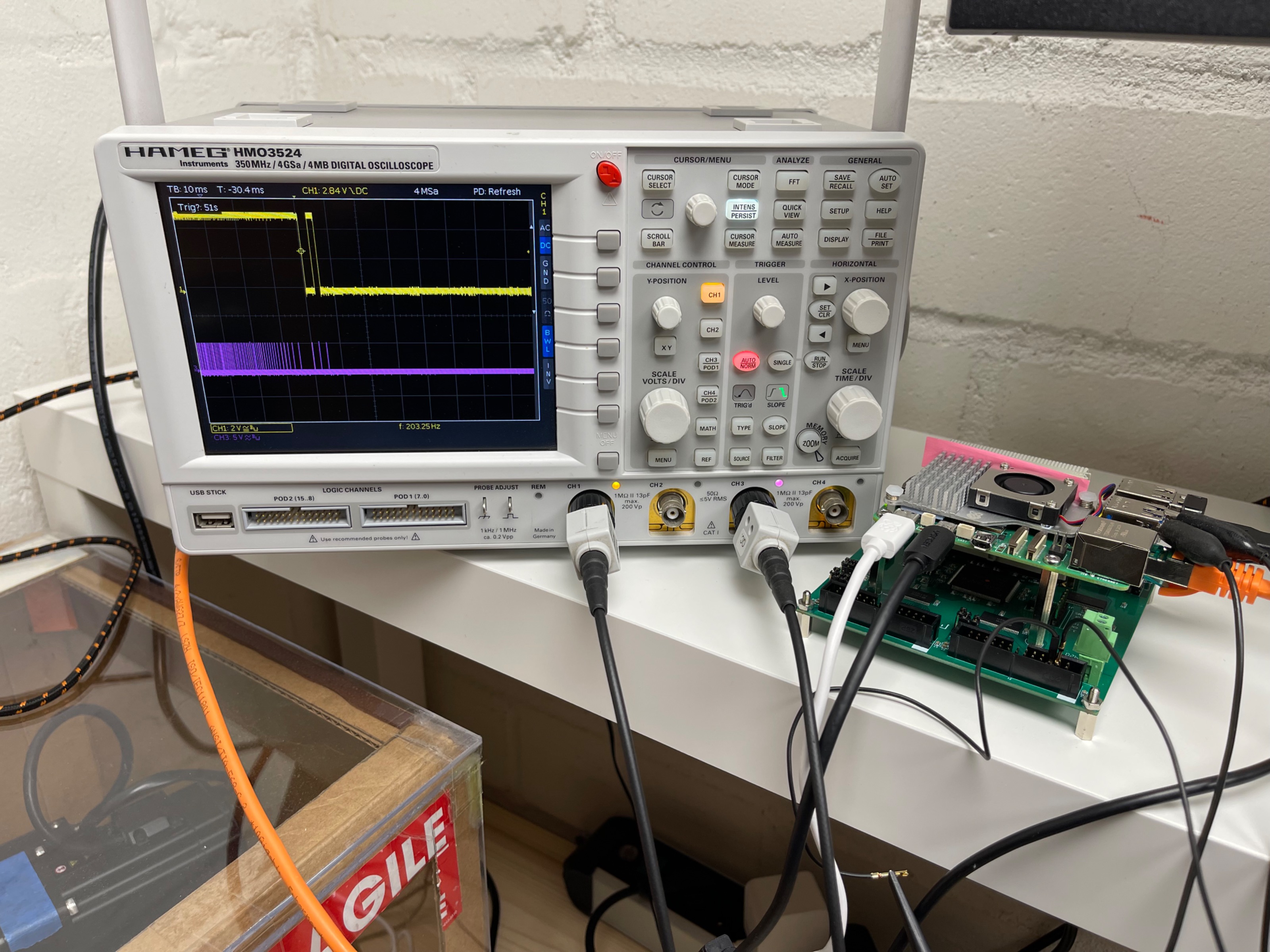
RPi5 and 7C81, manual control is choppy was created by AkkiSan
RPi5 and 7C81, manual control is choppy
Category: Basic Configuration
- scsmith1451

03 Aug 2025 14:41
Replied by scsmith1451 on topic Set program zero using XY positioning laser
Set program zero using XY positioning laser
Category: Advanced Configuration
- Thomas-1971
- Thomas-1971
03 Aug 2025 14:06
Replied by Thomas-1971 on topic ethercat verbindung zu bosch-rexroth HCS01 über eoe(ethernet over ethercat)
ethercat verbindung zu bosch-rexroth HCS01 über eoe(ethernet over ethercat)
Category: Deutsch
- AlexMagToast

03 Aug 2025 14:05
Replied by AlexMagToast on topic Arduino IO Expansion
Arduino IO Expansion
Category: Show Your Stuff
- PCW

03 Aug 2025 14:02
Replied by PCW on topic Mesaflash is not able to find 5i25
Mesaflash is not able to find 5i25
Category: Driver Boards
- GDTH
03 Aug 2025 13:54
Mesaflash is not able to find 5i25 was created by GDTH
Mesaflash is not able to find 5i25
Category: Driver Boards
- snowgoer540

03 Aug 2025 13:54
- TheTinkeringMechanic1
- TheTinkeringMechanic1
03 Aug 2025 13:35 - 03 Aug 2025 13:36
Replied by TheTinkeringMechanic1 on topic Spindle speed?
Spindle speed?
Category: Basic Configuration
- TheTinkeringMechanic1
- TheTinkeringMechanic1
03 Aug 2025 13:09
Replied by TheTinkeringMechanic1 on topic Spindle speed?
Spindle speed?
Category: Basic Configuration
Time to create page: 0.439 seconds