Search Results (Searched for: stepper spindle)
- Appliedmarine
- Appliedmarine
17 Oct 2024 05:45
Mazak Quickturn 10 x2 retrofit ideas! was created by Appliedmarine
Mazak Quickturn 10 x2 retrofit ideas!
Category: Turning
- automata
- automata
14 Oct 2024 09:30
Replied by automata on topic linuxcnc trajectory planner
linuxcnc trajectory planner
Category: General LinuxCNC Questions
- freemoore
- freemoore
13 Oct 2024 12:01
Replied by freemoore on topic Request for Mesa 5i23_7i48_7i52 firmware
Request for Mesa 5i23_7i48_7i52 firmware
Category: Driver Boards
- C0bra
- C0bra
08 Oct 2024 07:39
Replied by C0bra on topic Retrofiting Scm record 220
Retrofiting Scm record 220
Category: CNC Machines
- PhilipME

04 Oct 2024 03:32 - 04 Oct 2024 04:14
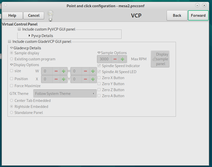
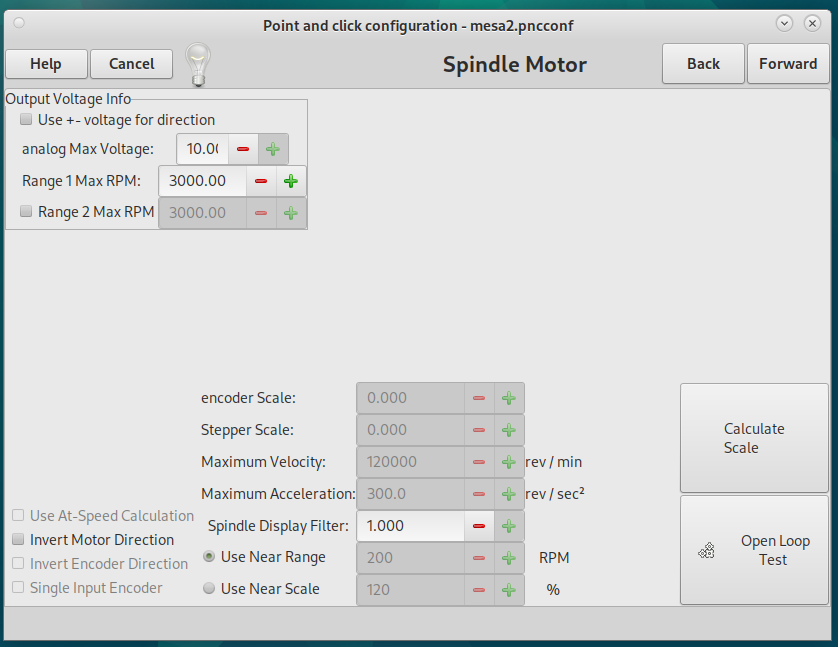
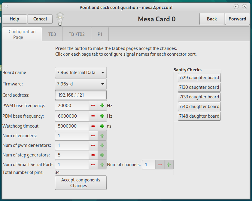
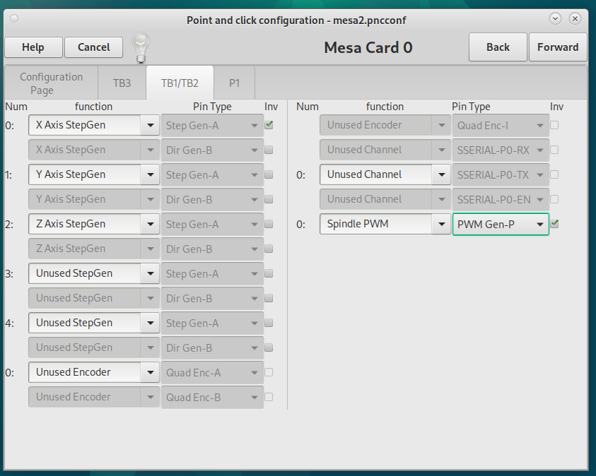
help-no voltage across mesa 7i96s spindle TB-2 pins 23 and 21 was created by PhilipME
help-no voltage across mesa 7i96s spindle TB-2 pins 23 and 21
Category: PnCConf Wizard
- spumco
- spumco
02 Oct 2024 05:05
Replied by spumco on topic Carousel Toolchanger
Carousel Toolchanger
Category: Advanced Configuration
- Aleksi
- Aleksi
02 Oct 2024 01:44
Replied by Aleksi on topic Connecting two 7i92 boards
Connecting two 7i92 boards
Category: General LinuxCNC Questions
- ConSonar
- ConSonar
30 Sep 2024 23:11
Help me decide. To Retrofit or not to Retrofit....... was created by ConSonar
Help me decide. To Retrofit or not to Retrofit.......
Category: General LinuxCNC Questions
- PhilipME
26 Sep 2024 04:31 - 26 Sep 2024 06:39
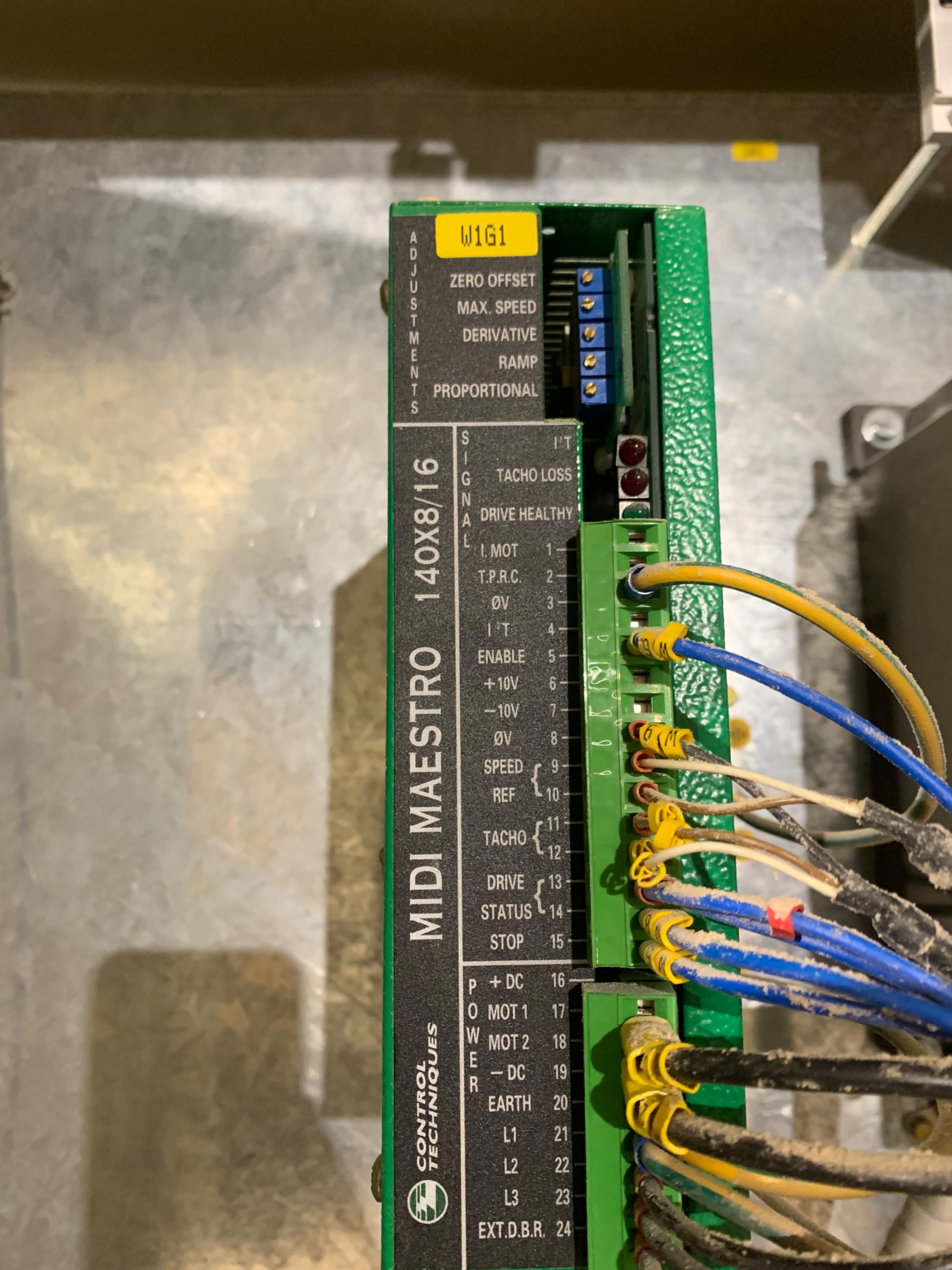
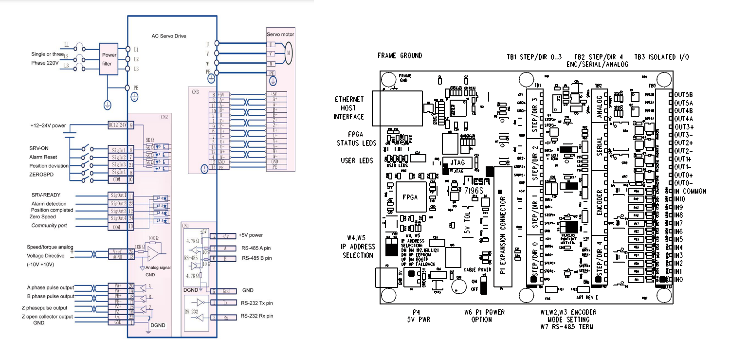
wiring mesa 7i96s to servo driver as a spindle was created by PhilipME
wiring mesa 7i96s to servo driver as a spindle
Category: Driver Boards
- PhilipME
23 Sep 2024 17:12
Replied by PhilipME on topic intending to use a servo motor as a spindle with mesa 7i96s
intending to use a servo motor as a spindle with mesa 7i96s
Category: PnCConf Wizard
- PhilipME
23 Sep 2024 14:26
Replied by PhilipME on topic intending to use a servo motor as a spindle with mesa 7i96s
intending to use a servo motor as a spindle with mesa 7i96s
Category: PnCConf Wizard
- tommylight

23 Sep 2024 14:17
Replied by tommylight on topic intending to use a servo motor as a spindle with mesa 7i96s
intending to use a servo motor as a spindle with mesa 7i96s
Category: PnCConf Wizard
- millikari
- millikari
22 Sep 2024 22:56
Indicator LED behavior of action buttons changed in version 2.9.3? was created by millikari
Indicator LED behavior of action buttons changed in version 2.9.3?
Category: Qtvcp
- xaxexa

20 Sep 2024 03:06
Replied by xaxexa on topic Remora - ethernet NVEM / EC300 / EC500 cnc board
Remora - ethernet NVEM / EC300 / EC500 cnc board
Category: Computers and Hardware
- 2703adam
- 2703adam
18 Sep 2024 18:13
New and overwhelmed. was created by 2703adam
New and overwhelmed.
Category: General LinuxCNC Questions
Time to create page: 0.933 seconds