Search Results (Searched for: stepper spindle)
05 Sep 2023 16:47
Replied by ihavenofish on topic Mini wannabe datron build
Mini wannabe datron build
Category: CNC Machines
ok, on the topic of pins....
multiswitch might not be ideal for the mpg, not sure now.
Lets use the 4 buttons on the pendant here.
Button 1: sets the axis you want to move.
Button 2: sets the increment the axis moves per encoder count.
Button 3: turns the spindle on and off.
Button 4: turns the coolant on and off.
3 and 4 are duplicates on the main keyboard which I don't think matters here.
Pressing the spindle button will change the state on a multi switch pin. If the spindle is already on, it turns it off and vice versa. M3 to M5 and back. I think this works. The downside is the LED indication could get confused if there was any sort of hiccup. No big deal though.
The coolant it the same. M7/M9. Same led feedback potential glitch, but not important.
Cycling the axis we may have an issue, but I do not fully grasp how this works internally, so maybe it is fine. When the machine starts, the MPG and the Control have no idea what each other has "set" for MPG functions. On a normal MPG the switches are persistent. If X is set, it is hitting that specific pin on the mesa, so linuxcnc KNOWS what the pendant is set to. With multiswitch you are flying blind a bit like using steppers. You need to preset a common default on both, and then hope there are no glitches that send the display out of sync with the control.
So our trade of having 1 pin per function instead of 4 (xyza) is decidedly more unreliable.
There is a middleground though maybe using binary code. 2 pins will get me 4 settings that cant go out of sync. So 2 mesa input pins (and 2 RP2040 output) per axis button.
So lets count up our IO properly.
M3/M5 - 1 pin, multiswitch on mesa. 1 pin on RP2040.
M4/M5 - 1 pin, multiswitch on mesa. 1 pin on RP2040. Uses same KEY as M3 with shift
M7/M9 - 1 pin, multiswitch on mesa. 1 pin on RP2040.
Cycle Start, Cycle Pause, And Cycle Stop. Hypothetically 3 more pins each, BUT, these are already tied to hotkeys, so potentially they do not need to be pins unless there is a reliability reasoning.
MPG wheel - 4 pins for differential correct? Nothing on the RP2040
MPG AXIS - 2 pins on the mesa, 2 pins on the RP2040, one key.
MPG increment - 2 pins on the mesa, 2 pins on the RP2040, one key.
Jog/MDI mode toggle - 1 pin, multiswitch on mesa. 1 pin on RP2040.
Enable would be one pin each too.
The override wheel i assume is really just another mpg. 2 pins each override (spindle and feed) on the mesa will just increment the override up and down. Pressing the encoder push switch would reset back to 100 so that is 1 more pin each. The RP2040 can read this encoder with 2 pins, and the pushbutton is in the key matrix. Then it needs 6 outputs back to the mesa. We do have the potential again for out led's to be wrong in a glitch, but those aren't super important and would get reset often.
The rest i'm not sure yet how they function.
1 - I want something to instigate a tool change. Press tool/magazine, then a number, then enter and it changes tool.
2 - I want to reference the machine. The ways its done on the DDCS is you press home, then the axis + you want to home, and then enter.
3 - Likewise the same for touching off. Zero, axis +, type a number (or zero), and then enter.
Past that we have some other transparent signals.
- Spindle overload error would be a pin on the mesa and rp2040. PLUS a pin on the rp2040 to read from the spindle drive.
We have used up all the basic IO on the rp2040 already here, but we only need a few more. So we need a 16 pin expander. Not a big deal. If we could serialise some of the lesser functions that would be nice, but I feel a $6 expansion of IO is much easier.
We are still pretty wide open for io on the mesa on the the 7i84.
The last thing we need in the middle is a level converter since all my RP2040 IO is 3,3v.
05 Sep 2023 01:34 - 05 Sep 2023 01:34
Replied by GeramyL on topic Remora - ethernet NVEM cnc board
Remora - ethernet NVEM cnc board
Category: Computers and OS's
Dropped my accuracy down to 0.0005mm per step about 10,000 pulses per per full rotation being 5mm.
With those changes I can accomplish the speeds i was doing last time at around 65khz on the stepper frequency with the links you gave me.
That all worked great and i'm happy with it, I was gonna flip anyways to 10,000 steps per full rotation anyways to give me some more force on my steppers. Now i'm trying to configure PWM for the spindle and the input, when i configure the input though it says no such pin found for remora.input.4 am i doing something wrong in my hal, and does someone have some small examples for the probe input and spindle pwm, without indexer? Thanks so much scott! I'm gonna take a look at your dma commit in a bit now, just saw the latest push.

04 Sep 2023 15:16
Replied by Donno on topic Mesa modbus and pktUart
Mesa modbus and pktUart
Category: Other User Interfaces
Yes I have Pos - 620ohm - 120 ohm - 620 ohm -Neg
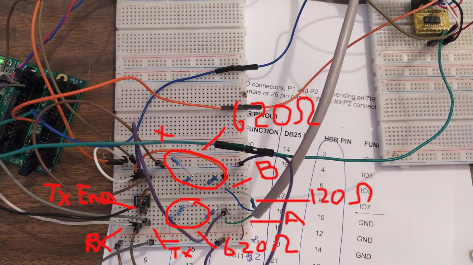
If i wire it any other way i get fault or if i remove 120ohm then i get a fault so i am pretty sure it is connecting. What are the default data and stop bit ?
Test.modHAL File

This is what i am expecting on address 0 to 8
If i wire it any other way i get fault or if i remove 120ohm then i get a fault so i am pretty sure it is connecting. What are the default data and stop bit ?
Test.mod
// Test Driver
#define MAX_MSG_LEN 16   // may be increased if necessary to max 251
#define DEBUG 3

static const hm2_modbus_chan_descriptor_t channels[] = {
/*  {TYPE,     FUNC, ADDR,   COUNT, pin_name} */
    {HAL_U32,   3,   0x0000, 1,     "test0"},
    {HAL_U32,   3,   0x0001, 1,     "test1"},
    {HAL_U32,   3,   0x0002, 1,     "test2"},
    {HAL_U32,   3,   0x0003, 1,     "test3"},
    {HAL_U32,   3,   0x0004, 1,     "test4"},
    {HAL_U32,   3,   0x0005, 1,     "test5"},
    {HAL_U32,   3,   0x0006, 1,     "test6"},
    {HAL_U32,   3,   0x0007, 1,     "test7"},
    {HAL_U32,   3,   0x0008, 1,     "test8"},
};# Generated by PNCconf at Mon Aug 28 20:19:10 2023
# Using LinuxCNC version: Master (2.9)
# If you make changes to this file, they will be
# overwritten when you run PNCconf again
loadrt [KINS]KINEMATICS
loadrt [EMCMOT]EMCMOT servo_period_nsec=[EMCMOT]SERVO_PERIOD num_joints=[KINS]JOINTS
loadrt hostmot2
loadrt hm2_eth board_ip="192.168.1.121" config="num_encoders=1 num_pwmgens=0 num_stepgens=2"
loadrt test ports=hm2_7i92.0.pktuart.0
setp hm2_7i92.0.watchdog.timeout_ns 5000000
loadrt pid names=pid.x,pid.z,pid.s
loadrt abs names=abs.spindle
loadrt lowpass names=lowpass.spindle
loadrt scale names=scale.spindle
loadrt near
addf hm2_7i92.0.read servo-thread
addf motion-command-handler servo-thread
addf motion-controller servo-thread
addf pid.x.do-pid-calcs servo-thread
addf pid.z.do-pid-calcs servo-thread
addf pid.s.do-pid-calcs servo-thread
addf scale.spindle servo-thread
addf abs.spindle servo-thread
addf lowpass.spindle servo-thread
addf near.0 servo-thread
addf hm2_7i92.0.write servo-thread
addf test.00 servo-thread
setp hm2_7i92.0.dpll.01.timer-us -50
setp hm2_7i92.0.stepgen.timer-number 1
setp test.00.address 1
setp test.00.baudrate 19200
setp test.00.parity 2
setp test.00.update-hz 0.1
# external output signals
# --- DOUT-00 ---
setp hm2_7i92.0.gpio.000.is_output true
net dout-00 => hm2_7i92.0.gpio.000.out
# --- SPINDLE-ENABLE ---
setp hm2_7i92.0.gpio.005.is_output true
net spindle-enable => hm2_7i92.0.gpio.005.out
# --- SPINDLE-CW ---
setp hm2_7i92.0.gpio.006.is_output true
net spindle-cw => hm2_7i92.0.gpio.006.out
# --- SPINDLE-CCW ---
setp hm2_7i92.0.gpio.007.is_output true
net spindle-ccw => hm2_7i92.0.gpio.007.out
# --- COOLANT-MIST ---
setp hm2_7i92.0.gpio.008.is_output true
net coolant-mist => hm2_7i92.0.gpio.008.out
# --- DOUT-01 ---
setp hm2_7i92.0.gpio.013.is_output true
net dout-01 => hm2_7i92.0.gpio.013.out
# --- DOUT-02 ---
setp hm2_7i92.0.gpio.015.is_output true
net dout-02 => hm2_7i92.0.gpio.015.out
# --- DOUT-03 ---
setp hm2_7i92.0.gpio.016.is_output true
net dout-03 => hm2_7i92.0.gpio.016.out
# --- ESTOP-OUT ---
setp hm2_7i92.0.gpio.030.is_output true
net estop-out => hm2_7i92.0.gpio.030.out
# --- MACHINE-IS-ENABLED ---
setp hm2_7i92.0.gpio.032.is_output true
net machine-is-enabled => hm2_7i92.0.gpio.032.out
# --- SPINDLE-ENABLE ---
setp hm2_7i92.0.gpio.033.is_output true
net spindle-enable => hm2_7i92.0.gpio.033.out
# external input signals
# --- HOME-X ---
net home-x <= hm2_7i92.0.gpio.012.in
# --- HOME-Z ---
net home-z <= hm2_7i92.0.gpio.014.in
# --- DIN-00 ---
net din-00 <= hm2_7i92.0.gpio.019.in
# --- DIN-01 ---
net din-01 <= hm2_7i92.0.gpio.020.in
# --- DIN-02 ---
net din-02 <= hm2_7i92.0.gpio.021.in
# --- DIN-03 ---
net din-03 <= hm2_7i92.0.gpio.022.in
# --- ESTOP-EXT ---
net estop-ext <= hm2_7i92.0.gpio.023.in
# --- PROBE-IN ---
net probe-in <= hm2_7i92.0.gpio.024.in
#*******************
# AXIS X JOINT 0
#*******************
setp pid.x.Pgain [JOINT_0]P
setp pid.x.Igain [JOINT_0]I
setp pid.x.Dgain [JOINT_0]D
setp pid.x.bias [JOINT_0]BIAS
setp pid.x.FF0 [JOINT_0]FF0
setp pid.x.FF1 [JOINT_0]FF1
setp pid.x.FF2 [JOINT_0]FF2
setp pid.x.deadband [JOINT_0]DEADBAND
setp pid.x.maxoutput [JOINT_0]MAX_OUTPUT
setp pid.x.error-previous-target true
# This setting is to limit bogus stepgen
# velocity corrections caused by position
# feedback sample time jitter.
setp pid.x.maxerror 0.012700
net x-index-enable => pid.x.index-enable
net x-enable => pid.x.enable
net x-pos-cmd => pid.x.command
net x-pos-fb => pid.x.feedback
net x-output <= pid.x.output
# Step Gen signals/setup
setp hm2_7i92.0.stepgen.00.dirsetup [JOINT_0]DIRSETUP
setp hm2_7i92.0.stepgen.00.dirhold [JOINT_0]DIRHOLD
setp hm2_7i92.0.stepgen.00.steplen [JOINT_0]STEPLEN
setp hm2_7i92.0.stepgen.00.stepspace [JOINT_0]STEPSPACE
setp hm2_7i92.0.stepgen.00.position-scale [JOINT_0]STEP_SCALE
setp hm2_7i92.0.stepgen.00.step_type 0
setp hm2_7i92.0.stepgen.00.control-type 1
setp hm2_7i92.0.stepgen.00.maxaccel [JOINT_0]STEPGEN_MAXACCEL
setp hm2_7i92.0.stepgen.00.maxvel [JOINT_0]STEPGEN_MAXVEL
# ---closedloop stepper signals---
net x-pos-cmd <= joint.0.motor-pos-cmd
net x-vel-cmd <= joint.0.vel-cmd
net x-output => hm2_7i92.0.stepgen.00.velocity-cmd
net x-pos-fb <= hm2_7i92.0.stepgen.00.position-fb
net x-pos-fb => joint.0.motor-pos-fb
net x-enable <= joint.0.amp-enable-out
net x-enable => hm2_7i92.0.stepgen.00.enable
# ---setup home / limit switch signals---
net home-x => joint.0.home-sw-in
net x-neg-limit => joint.0.neg-lim-sw-in
net x-pos-limit => joint.0.pos-lim-sw-in
#*******************
# AXIS Z JOINT 1
#*******************
setp pid.z.Pgain [JOINT_1]P
setp pid.z.Igain [JOINT_1]I
setp pid.z.Dgain [JOINT_1]D
setp pid.z.bias [JOINT_1]BIAS
setp pid.z.FF0 [JOINT_1]FF0
setp pid.z.FF1 [JOINT_1]FF1
setp pid.z.FF2 [JOINT_1]FF2
setp pid.z.deadband [JOINT_1]DEADBAND
setp pid.z.maxoutput [JOINT_1]MAX_OUTPUT
setp pid.z.error-previous-target true
# This setting is to limit bogus stepgen
# velocity corrections caused by position
# feedback sample time jitter.
setp pid.z.maxerror 0.012700
net z-index-enable => pid.z.index-enable
net z-enable => pid.z.enable
net z-pos-cmd => pid.z.command
net z-pos-fb => pid.z.feedback
net z-output <= pid.z.output
# Step Gen signals/setup
setp hm2_7i92.0.stepgen.01.dirsetup [JOINT_1]DIRSETUP
setp hm2_7i92.0.stepgen.01.dirhold [JOINT_1]DIRHOLD
setp hm2_7i92.0.stepgen.01.steplen [JOINT_1]STEPLEN
setp hm2_7i92.0.stepgen.01.stepspace [JOINT_1]STEPSPACE
setp hm2_7i92.0.stepgen.01.position-scale [JOINT_1]STEP_SCALE
setp hm2_7i92.0.stepgen.01.step_type 0
setp hm2_7i92.0.stepgen.01.control-type 1
setp hm2_7i92.0.stepgen.01.maxaccel [JOINT_1]STEPGEN_MAXACCEL
setp hm2_7i92.0.stepgen.01.maxvel [JOINT_1]STEPGEN_MAXVEL
# ---closedloop stepper signals---
net z-pos-cmd <= joint.1.motor-pos-cmd
net z-vel-cmd <= joint.1.vel-cmd
net z-output => hm2_7i92.0.stepgen.01.velocity-cmd
net z-pos-fb <= hm2_7i92.0.stepgen.01.position-fb
net z-pos-fb => joint.1.motor-pos-fb
net z-enable <= joint.1.amp-enable-out
net z-enable => hm2_7i92.0.stepgen.01.enable
# ---setup home / limit switch signals---
net home-z => joint.1.home-sw-in
net z-neg-limit => joint.1.neg-lim-sw-in
net z-pos-limit => joint.1.pos-lim-sw-in
#*******************
# SPINDLE
#*******************
setp pid.s.Pgain [SPINDLE_0]P
setp pid.s.Igain [SPINDLE_0]I
setp pid.s.Dgain [SPINDLE_0]D
setp pid.s.bias [SPINDLE_0]BIAS
setp pid.s.FF0 [SPINDLE_0]FF0
setp pid.s.FF1 [SPINDLE_0]FF1
setp pid.s.FF2 [SPINDLE_0]FF2
setp pid.s.deadband [SPINDLE_0]DEADBAND
setp pid.s.maxoutput [SPINDLE_0]MAX_OUTPUT
setp pid.s.error-previous-target true
net spindle-index-enable => pid.s.index-enable
net spindle-enable => pid.s.enable
net spindle-vel-cmd-rpm-abs => pid.s.command
net spindle-vel-fb-rpm-abs => pid.s.feedback
net spindle-output <= pid.s.output
# ---Encoder feedback signals/setup---
setp hm2_7i92.0.encoder.00.counter-mode 0
setp hm2_7i92.0.encoder.00.filter 1
setp hm2_7i92.0.encoder.00.index-invert 0
setp hm2_7i92.0.encoder.00.index-mask 0
setp hm2_7i92.0.encoder.00.index-mask-invert 0
setp hm2_7i92.0.encoder.00.scale [SPINDLE_0]ENCODER_SCALE
net spindle-revs <= hm2_7i92.0.encoder.00.position
net spindle-vel-fb-rps <= hm2_7i92.0.encoder.00.velocity
net spindle-vel-fb-rpm <= hm2_7i92.0.encoder.00.velocity-rpm
net spindle-index-enable <=> hm2_7i92.0.encoder.00.index-enable
# ---setup spindle control signals---
net spindle-vel-cmd-rps <= spindle.0.speed-out-rps
net spindle-vel-cmd-rps-abs <= spindle.0.speed-out-rps-abs
net spindle-vel-cmd-rpm <= spindle.0.speed-out
net spindle-vel-cmd-rpm-abs <= spindle.0.speed-out-abs
net spindle-enable <= spindle.0.on
net spindle-cw <= spindle.0.forward
net spindle-ccw <= spindle.0.reverse
net spindle-brake <= spindle.0.brake
net spindle-revs => spindle.0.revs
net spindle-at-speed => spindle.0.at-speed
net spindle-vel-fb-rps => spindle.0.speed-in
net spindle-index-enable <=> spindle.0.index-enable
# ---Setup spindle at speed signals---
net spindle-vel-cmd-rps => near.0.in1
net spindle-vel-fb-rps => near.0.in2
net spindle-at-speed <= near.0.out
setp near.0.scale 1.000000
setp near.0.difference 0.166667
# Use ACTUAL spindle velocity from spindle encoder
# spindle-velocity bounces around so we filter it with lowpass
# spindle-velocity is signed so we use absolute component to remove sign
# ACTUAL velocity is in RPS not RPM so we scale it.
setp scale.spindle.gain 60
setp lowpass.spindle.gain 1.000000
net spindle-vel-fb-rps => scale.spindle.in
net spindle-fb-rpm scale.spindle.out => abs.spindle.in
net spindle-fb-rpm-abs abs.spindle.out => lowpass.spindle.in
net spindle-fb-rpm-abs-filtered lowpass.spindle.out
#******************************
# connect miscellaneous signals
#******************************
# ---HALUI signals---
net axis-select-x halui.axis.x.select
net jog-x-pos halui.axis.x.plus
net jog-x-neg halui.axis.x.minus
net jog-x-analog halui.axis.x.analog
net x-is-homed halui.joint.0.is-homed
net axis-select-z halui.axis.z.select
net jog-z-pos halui.axis.z.plus
net jog-z-neg halui.axis.z.minus
net jog-z-analog halui.axis.z.analog
net z-is-homed halui.joint.1.is-homed
net jog-selected-pos halui.axis.selected.plus
net jog-selected-neg halui.axis.selected.minus
net spindle-manual-cw halui.spindle.0.forward
net spindle-manual-ccw halui.spindle.0.reverse
net spindle-manual-stop halui.spindle.0.stop
net machine-is-on halui.machine.is-on
net jog-speed halui.axis.jog-speed
net MDI-mode halui.mode.is-mdi
# ---coolant signals---
net coolant-mist <= iocontrol.0.coolant-mist
net coolant-flood <= iocontrol.0.coolant-flood
# ---probe signal---
net probe-in => motion.probe-input
# ---motion control signals---
net in-position <= motion.in-position
net machine-is-enabled <= motion.motion-enabled
# ---digital in / out signals---
net dout-00 <= motion.digital-out-00
net dout-01 <= motion.digital-out-01
net dout-02 <= motion.digital-out-02
net dout-03 <= motion.digital-out-03
net din-00 => motion.digital-in-00
net din-01 => motion.digital-in-01
net din-02 => motion.digital-in-02
net din-03 => motion.digital-in-03
# ---estop signals---
net estop-out <= iocontrol.0.user-enable-out
net estop-ext => iocontrol.0.emc-enable-in
# ---manual tool change signals---
net tool-change-request <= iocontrol.0.tool-change
net tool-change-confirmed => iocontrol.0.tool-changed
net tool-number <= iocontrol.0.tool-prep-number
# ---Use external manual tool change dialog---
loadusr -W hal_manualtoolchange
net tool-change-request => hal_manualtoolchange.change
net tool-change-confirmed <= hal_manualtoolchange.changed
net tool-number => hal_manualtoolchange.number
# ---ignore tool prepare requests---
net tool-prepare-loopback iocontrol.0.tool-prepare => iocontrol.0.tool-prepared
This is what i am expecting on address 0 to 8
[color=#ff5454]A5 Servo Driver |  16:59:43                                                                                                                                [/color][color=#000000] [/color]
[color=#e74c3c]0 : 14130 | 1 :  0 | 2 :  0 | 3 :  0 | 4 :  0 | 5 :  0 | 6 :  0 | 7 :  0 | 8 :  14100 |[/color][color=#5454ff] [/color]
04 Sep 2023 03:38
Replied by spumco on topic 16 Pocket tool changer with PB and carousel.comp (Working config for reference)
16 Pocket tool changer with PB and carousel.comp (Working config for reference)
Category: QtPyVCP
The carousel encoding can be done in a number of ways. If "INDEX" encoding is chosen you will need two sensors, and one trigger (flag) per pocket, plus one trigger per revolution.
One of the sensors is the 'home' sensor, the other is the 'pocket' sensor. Both of these are connected to carousel.comp via HAL.
On first enable, carousel.comp will home the ATC until the home sensor is triggered. This will be pocket #1. After that, it will move to the correct pocket by counting up/down the index sensor pulses.
This encoding scheme will work with both a Geneva drive as well as a servo/stepper-driven rotation.
If "COUNTS" mode is selected, only a home sensor is required. You pre-program the number of steps between pocket centers, and carousel output pulses through a stepgen to move to the correct pocket. As with index mode, once homed, carousel.comp keeps track of how many pockets have passed up/down from the home position. All you have to do is send it a destination pocket using a motion.analog-out signal from g-code.
The 'flags' mentioned earlier can be holes in the ATC platter that trigger the inductive sensors. Or they can be pins, or anything else that triggers the sensors repeatably. Some people have used microswitches instead of proximity sensors. Even optical sensors are suitable if you have room for a slotted wheel of some sort.
I think the laser sensor(s) in the original description are for determining the presence (or not) of a tool in a pocket, as well the position of the drawbar. They are not required for carousel.comp to control an ATC, but it does add an additional layer of safety in case the tool is not seated in the spindle taper properly or if a tool is in a pocket when one isn't supposed to be there.

03 Sep 2023 01:12
Replied by tommylight on topic Only one Y Stepper is working
Only one Y Stepper is working
Category: PnCConf Wizard
There is nothing set up for tandem axis in your files, just 3 axis and spindle.
Use PncConf to create a new config, choose 4 stepgens, choose axis x, choose axis y, choose tandem axis y2, choose axis z.
One more, thing, those two Y axis must have separate home/limit switches.
Use PncConf to create a new config, choose 4 stepgens, choose axis x, choose axis y, choose tandem axis y2, choose axis z.
One more, thing, those two Y axis must have separate home/limit switches.
02 Sep 2023 17:53
Replied by Donno on topic Mesa modbus and pktUart
Mesa modbus and pktUart
Category: Other User Interfaces
mesaflash --device 7i92T --addr 192.168.1.121 --readhmid
Hal File loadrt mesa_modbus_A5_Driver names=hm2_7i92.0.pktuart.0 and addf mesa_modbus_A5_Driver servo-thread
donno@linuxcnc:~/Desktop $ mesaflash --device 7i92T --addr 192.168.1.121 --readhmid
Configuration Name: HOSTMOT2

General configuration information:

  BoardName : MESA7I92
  FPGA Size: 20 KGates
  FPGA Pins: 256
  Number of IO Ports: 2
  Width of one I/O port: 17
  Clock Low frequency: 100.0000 MHz
  Clock High frequency: 175.0000 MHz
  IDROM Type: 3
  Instance Stride 0: 4
  Instance Stride 1: 64
  Register Stride 0: 256
  Register Stride 1: 256

Modules in configuration:

  Module: DPLL
  There are 1 of DPLL in configuration
  Version: 0
  Registers: 7
  BaseAddress: 7000
  ClockFrequency: 100.000 MHz
  Register Stride: 256 bytes
  Instance Stride: 4 bytes

  Module: WatchDog
  There are 1 of WatchDog in configuration
  Version: 0
  Registers: 3
  BaseAddress: 0C00
  ClockFrequency: 100.000 MHz
  Register Stride: 256 bytes
  Instance Stride: 4 bytes

  Module: IOPort
  There are 2 of IOPort in configuration
  Version: 0
  Registers: 5
  BaseAddress: 1000
  ClockFrequency: 100.000 MHz
  Register Stride: 256 bytes
  Instance Stride: 4 bytes

  Module: QCount
  There are 2 of QCount in configuration
  Version: 2
  Registers: 5
  BaseAddress: 3000
  ClockFrequency: 100.000 MHz
  Register Stride: 256 bytes
  Instance Stride: 4 bytes

  Module: StepGen
  There are 10 of StepGen in configuration
  Version: 2
  Registers: 10
  BaseAddress: 2000
  ClockFrequency: 100.000 MHz
  Register Stride: 256 bytes
  Instance Stride: 4 bytes

  Module: PWM
  There are 2 of PWM in configuration
  Version: 0
  Registers: 5
  BaseAddress: 4100
  ClockFrequency: 175.000 MHz
  Register Stride: 256 bytes
  Instance Stride: 4 bytes

  Module: LED
  There are 1 of LED in configuration
  Version: 0
  Registers: 1
  BaseAddress: 0200
  ClockFrequency: 100.000 MHz
  Register Stride: 256 bytes
  Instance Stride: 4 bytes

  Module: PktUARTTX
  There are 1 of PktUARTTX in configuration
  Version: 0
  Registers: 4
  BaseAddress: 6100
  ClockFrequency: 100.000 MHz
  Register Stride: 256 bytes
  Instance Stride: 4 bytes

  Module: PktUARTRX
  There are 1 of PktUARTRX in configuration
  Version: 0
  Registers: 4
  BaseAddress: 6500
  ClockFrequency: 100.000 MHz
  Register Stride: 256 bytes
  Instance Stride: 4 bytes

Configuration pin-out:

IO Connections for P2
DB25 pin#             I/O   Pri. func    Sec. func        Chan     Sec. Pin func   Sec. Pin Dir

 1                      0   IOPort       PWM              0        PWM             (Out)
14                      1   IOPort       StepGen          0        Step/Table1     (Out)
 2                      2   IOPort       StepGen          0        Dir/Table2      (Out)
15                      3   IOPort       StepGen          1        Step/Table1     (Out)
 3                      4   IOPort       StepGen          1        Dir/Table2      (Out)
16                      5   IOPort       None
 4                      6   IOPort       None
17                      7   IOPort       None
 5                      8   IOPort       None
 6                      9   IOPort       QCount           0        Quad-A          (In)
 7                     10   IOPort       QCount           0        Quad-B          (In)
 8                     11   IOPort       QCount           0        Quad-IDX        (In)
 9                     12   IOPort       None
10                     13   IOPort       None
11                     14   IOPort       None
12                     15   IOPort       None
13                     16   IOPort       None

IO Connections for P1
DB25 pin#             I/O   Pri. func    Sec. func        Chan     Sec. Pin func   Sec. Pin Dir

 1                     17   IOPort       PktUARTRX        0        RXData          (In)
14                     18   IOPort       PktUARTTX        0        TXData          (Out)
 2                     19   IOPort       PktUARTTX        0        TXEna           (Out)
15                     20   IOPort       None
 3                     21   IOPort       None
16                     22   IOPort       None
 4                     23   IOPort       None
17                     24   IOPort       None
 5                     25   IOPort       None
 6                     26   IOPort       None
 7                     27   IOPort       None
 8                     28   IOPort       None
 9                     29   IOPort       None
10                     30   IOPort       None
11                     31   IOPort       None
12                     32   IOPort       None
13                     33   IOPort       None
Hal File loadrt mesa_modbus_A5_Driver names=hm2_7i92.0.pktuart.0 and addf mesa_modbus_A5_Driver servo-thread
# Generated by PNCconf at Mon Aug 28 20:19:10 2023
# Using LinuxCNC version:  Master (2.9)
# If you make changes to this file, they will be
# overwritten when you run PNCconf again

loadrt [KINS]KINEMATICS
loadrt [EMCMOT]EMCMOT servo_period_nsec=[EMCMOT]SERVO_PERIOD num_joints=[KINS]JOINTS
loadrt hostmot2
loadrt hm2_eth board_ip="192.168.1.121" config="num_encoders=1 num_pwmgens=0 num_stepgens=2"
loadrt mesa_modbus_A5_Driver names=hm2_7i92.0.pktuart.0

setp    hm2_7i92.0.watchdog.timeout_ns 5000000
loadrt pid names=pid.x,pid.z,pid.s
loadrt abs names=abs.spindle
loadrt lowpass names=lowpass.spindle
loadrt scale names=scale.spindle
loadrt near

addf hm2_7i92.0.read          servo-thread
addf motion-command-handler   servo-thread
addf motion-controller        servo-thread
addf pid.x.do-pid-calcs       servo-thread
addf pid.z.do-pid-calcs       servo-thread
addf pid.s.do-pid-calcs       servo-thread
addf scale.spindle            servo-thread
addf abs.spindle              servo-thread
addf lowpass.spindle          servo-thread
addf near.0                   servo-thread
addf hm2_7i92.0.write         servo-thread
addf mesa_modbus_A5_Driver      servo-thread
setp hm2_7i92.0.dpll.01.timer-us -50
setp hm2_7i92.0.stepgen.timer-number 1

# external output signals

# --- DOUT-00 ---
setp hm2_7i92.0.gpio.000.is_output true
net dout-00  =>     hm2_7i92.0.gpio.000.out

# --- SPINDLE-ENABLE ---
setp hm2_7i92.0.gpio.005.is_output true
net spindle-enable  =>     hm2_7i92.0.gpio.005.out

# --- SPINDLE-CW ---
setp hm2_7i92.0.gpio.006.is_output true
net spindle-cw  =>     hm2_7i92.0.gpio.006.out

# --- SPINDLE-CCW ---
setp hm2_7i92.0.gpio.007.is_output true
net spindle-ccw  =>     hm2_7i92.0.gpio.007.out

# --- COOLANT-MIST ---
setp hm2_7i92.0.gpio.008.is_output true
net coolant-mist  =>     hm2_7i92.0.gpio.008.out

# --- DOUT-01 ---
setp hm2_7i92.0.gpio.013.is_output true
net dout-01  =>     hm2_7i92.0.gpio.013.out

# --- DOUT-02 ---
setp hm2_7i92.0.gpio.015.is_output true
net dout-02  =>     hm2_7i92.0.gpio.015.out

# --- DOUT-03 ---
setp hm2_7i92.0.gpio.016.is_output true
net dout-03  =>     hm2_7i92.0.gpio.016.out

# --- ESTOP-OUT ---
setp hm2_7i92.0.gpio.030.is_output true
net estop-out  =>     hm2_7i92.0.gpio.030.out

# --- MACHINE-IS-ENABLED ---
setp hm2_7i92.0.gpio.032.is_output true
net machine-is-enabled  =>     hm2_7i92.0.gpio.032.out

# --- SPINDLE-ENABLE ---
setp hm2_7i92.0.gpio.033.is_output true
net spindle-enable  =>     hm2_7i92.0.gpio.033.out


# external input signals

# --- HOME-X ---
net home-x     <=  hm2_7i92.0.gpio.012.in

# --- HOME-Z ---
net home-z     <=  hm2_7i92.0.gpio.014.in

# --- DIN-00 ---
net din-00     <=  hm2_7i92.0.gpio.019.in

# --- DIN-01 ---
net din-01     <=  hm2_7i92.0.gpio.020.in

# --- DIN-02 ---
net din-02     <=  hm2_7i92.0.gpio.021.in

# --- DIN-03 ---
net din-03     <=  hm2_7i92.0.gpio.022.in

# --- ESTOP-EXT ---
net estop-ext     <=  hm2_7i92.0.gpio.023.in

# --- PROBE-IN ---
net probe-in     <=  hm2_7i92.0.gpio.024.in


#*******************
#  AXIS X JOINT 0
#*******************

setp   pid.x.Pgain     [JOINT_0]P
setp   pid.x.Igain     [JOINT_0]I
setp   pid.x.Dgain     [JOINT_0]D
setp   pid.x.bias      [JOINT_0]BIAS
setp   pid.x.FF0       [JOINT_0]FF0
setp   pid.x.FF1       [JOINT_0]FF1
setp   pid.x.FF2       [JOINT_0]FF2
setp   pid.x.deadband  [JOINT_0]DEADBAND
setp   pid.x.maxoutput [JOINT_0]MAX_OUTPUT
setp   pid.x.error-previous-target true
# This setting is to limit bogus stepgen
# velocity corrections caused by position
# feedback sample time jitter.
setp   pid.x.maxerror 0.012700

net x-index-enable  =>  pid.x.index-enable
net x-enable        =>  pid.x.enable
net x-pos-cmd       =>  pid.x.command
net x-pos-fb        =>  pid.x.feedback
net x-output        <=  pid.x.output

# Step Gen signals/setup

setp   hm2_7i92.0.stepgen.00.dirsetup        [JOINT_0]DIRSETUP
setp   hm2_7i92.0.stepgen.00.dirhold         [JOINT_0]DIRHOLD
setp   hm2_7i92.0.stepgen.00.steplen         [JOINT_0]STEPLEN
setp   hm2_7i92.0.stepgen.00.stepspace       [JOINT_0]STEPSPACE
setp   hm2_7i92.0.stepgen.00.position-scale  [JOINT_0]STEP_SCALE
setp   hm2_7i92.0.stepgen.00.step_type        0
setp   hm2_7i92.0.stepgen.00.control-type     1
setp   hm2_7i92.0.stepgen.00.maxaccel         [JOINT_0]STEPGEN_MAXACCEL
setp   hm2_7i92.0.stepgen.00.maxvel           [JOINT_0]STEPGEN_MAXVEL

# ---closedloop stepper signals---

net x-pos-cmd    <= joint.0.motor-pos-cmd
net x-vel-cmd    <= joint.0.vel-cmd
net x-output     => hm2_7i92.0.stepgen.00.velocity-cmd
net x-pos-fb     <= hm2_7i92.0.stepgen.00.position-fb
net x-pos-fb     => joint.0.motor-pos-fb
net x-enable     <= joint.0.amp-enable-out
net x-enable     => hm2_7i92.0.stepgen.00.enable

# ---setup home / limit switch signals---

net home-x     =>  joint.0.home-sw-in
net x-neg-limit     =>  joint.0.neg-lim-sw-in
net x-pos-limit     =>  joint.0.pos-lim-sw-in

#*******************
#  AXIS Z JOINT 1
#*******************

setp   pid.z.Pgain     [JOINT_1]P
setp   pid.z.Igain     [JOINT_1]I
setp   pid.z.Dgain     [JOINT_1]D
setp   pid.z.bias      [JOINT_1]BIAS
setp   pid.z.FF0       [JOINT_1]FF0
setp   pid.z.FF1       [JOINT_1]FF1
setp   pid.z.FF2       [JOINT_1]FF2
setp   pid.z.deadband  [JOINT_1]DEADBAND
setp   pid.z.maxoutput [JOINT_1]MAX_OUTPUT
setp   pid.z.error-previous-target true
# This setting is to limit bogus stepgen
# velocity corrections caused by position
# feedback sample time jitter.
setp   pid.z.maxerror 0.012700

net z-index-enable  =>  pid.z.index-enable
net z-enable        =>  pid.z.enable
net z-pos-cmd       =>  pid.z.command
net z-pos-fb        =>  pid.z.feedback
net z-output        <=  pid.z.output

# Step Gen signals/setup

setp   hm2_7i92.0.stepgen.01.dirsetup        [JOINT_1]DIRSETUP
setp   hm2_7i92.0.stepgen.01.dirhold         [JOINT_1]DIRHOLD
setp   hm2_7i92.0.stepgen.01.steplen         [JOINT_1]STEPLEN
setp   hm2_7i92.0.stepgen.01.stepspace       [JOINT_1]STEPSPACE
setp   hm2_7i92.0.stepgen.01.position-scale  [JOINT_1]STEP_SCALE
setp   hm2_7i92.0.stepgen.01.step_type        0
setp   hm2_7i92.0.stepgen.01.control-type     1
setp   hm2_7i92.0.stepgen.01.maxaccel         [JOINT_1]STEPGEN_MAXACCEL
setp   hm2_7i92.0.stepgen.01.maxvel           [JOINT_1]STEPGEN_MAXVEL

# ---closedloop stepper signals---

net z-pos-cmd    <= joint.1.motor-pos-cmd
net z-vel-cmd    <= joint.1.vel-cmd
net z-output     => hm2_7i92.0.stepgen.01.velocity-cmd
net z-pos-fb     <= hm2_7i92.0.stepgen.01.position-fb
net z-pos-fb     => joint.1.motor-pos-fb
net z-enable     <= joint.1.amp-enable-out
net z-enable     => hm2_7i92.0.stepgen.01.enable

# ---setup home / limit switch signals---

net home-z     =>  joint.1.home-sw-in
net z-neg-limit     =>  joint.1.neg-lim-sw-in
net z-pos-limit     =>  joint.1.pos-lim-sw-in

#*******************
#  SPINDLE
#*******************

setp   pid.s.Pgain     [SPINDLE_0]P
setp   pid.s.Igain     [SPINDLE_0]I
setp   pid.s.Dgain     [SPINDLE_0]D
setp   pid.s.bias      [SPINDLE_0]BIAS
setp   pid.s.FF0       [SPINDLE_0]FF0
setp   pid.s.FF1       [SPINDLE_0]FF1
setp   pid.s.FF2       [SPINDLE_0]FF2
setp   pid.s.deadband  [SPINDLE_0]DEADBAND
setp   pid.s.maxoutput [SPINDLE_0]MAX_OUTPUT
setp   pid.s.error-previous-target true

net spindle-index-enable  =>  pid.s.index-enable
net spindle-enable        =>  pid.s.enable
net spindle-vel-cmd-rpm-abs     => pid.s.command
net spindle-vel-fb-rpm-abs      => pid.s.feedback
net spindle-output        <=  pid.s.output

# ---Encoder feedback signals/setup---

setp    hm2_7i92.0.encoder.00.counter-mode 0
setp    hm2_7i92.0.encoder.00.filter 1
setp    hm2_7i92.0.encoder.00.index-invert 0
setp    hm2_7i92.0.encoder.00.index-mask 0
setp    hm2_7i92.0.encoder.00.index-mask-invert 0
setp    hm2_7i92.0.encoder.00.scale  [SPINDLE_0]ENCODER_SCALE

net spindle-revs             <=   hm2_7i92.0.encoder.00.position
net spindle-vel-fb-rps       <=   hm2_7i92.0.encoder.00.velocity
net spindle-vel-fb-rpm       <=   hm2_7i92.0.encoder.00.velocity-rpm
net spindle-index-enable     <=>  hm2_7i92.0.encoder.00.index-enable

# ---setup spindle control signals---

net spindle-vel-cmd-rps        <=  spindle.0.speed-out-rps
net spindle-vel-cmd-rps-abs    <=  spindle.0.speed-out-rps-abs
net spindle-vel-cmd-rpm        <=  spindle.0.speed-out
net spindle-vel-cmd-rpm-abs    <=  spindle.0.speed-out-abs
net spindle-enable             <=  spindle.0.on
net spindle-cw                 <=  spindle.0.forward
net spindle-ccw                <=  spindle.0.reverse
net spindle-brake              <=  spindle.0.brake
net spindle-revs               =>  spindle.0.revs
net spindle-at-speed           =>  spindle.0.at-speed
net spindle-vel-fb-rps         =>  spindle.0.speed-in
net spindle-index-enable      <=>  spindle.0.index-enable

# ---Setup spindle at speed signals---

net spindle-vel-cmd-rps    =>  near.0.in1
net spindle-vel-fb-rps         =>  near.0.in2
net spindle-at-speed       <=  near.0.out
setp near.0.scale 1.000000
setp near.0.difference 0.166667

#  Use ACTUAL spindle velocity from spindle encoder
#  spindle-velocity bounces around so we filter it with lowpass
#  spindle-velocity is signed so we use absolute component to remove sign
#  ACTUAL velocity is in RPS not RPM so we scale it.

setp     scale.spindle.gain 60
setp     lowpass.spindle.gain 1.000000
net spindle-vel-fb-rps        =>     scale.spindle.in
net spindle-fb-rpm               scale.spindle.out       =>   abs.spindle.in
net spindle-fb-rpm-abs           abs.spindle.out         =>   lowpass.spindle.in
net spindle-fb-rpm-abs-filtered  lowpass.spindle.out

#******************************
# connect miscellaneous signals
#******************************

#  ---HALUI signals---

net axis-select-x  halui.axis.x.select
net jog-x-pos      halui.axis.x.plus
net jog-x-neg      halui.axis.x.minus
net jog-x-analog   halui.axis.x.analog
net x-is-homed     halui.joint.0.is-homed
net axis-select-z  halui.axis.z.select
net jog-z-pos      halui.axis.z.plus
net jog-z-neg      halui.axis.z.minus
net jog-z-analog   halui.axis.z.analog
net z-is-homed     halui.joint.1.is-homed
net jog-selected-pos      halui.axis.selected.plus
net jog-selected-neg      halui.axis.selected.minus
net spindle-manual-cw     halui.spindle.0.forward
net spindle-manual-ccw    halui.spindle.0.reverse
net spindle-manual-stop   halui.spindle.0.stop
net machine-is-on         halui.machine.is-on
net jog-speed             halui.axis.jog-speed
net MDI-mode              halui.mode.is-mdi

#  ---coolant signals---

net coolant-mist      <=  iocontrol.0.coolant-mist
net coolant-flood     <=  iocontrol.0.coolant-flood

#  ---probe signal---

net probe-in     =>  motion.probe-input

#  ---motion control signals---

net in-position               <=  motion.in-position
net machine-is-enabled        <=  motion.motion-enabled

#  ---digital in / out signals---

net dout-00     <=  motion.digital-out-00
net dout-01     <=  motion.digital-out-01
net dout-02     <=  motion.digital-out-02
net dout-03     <=  motion.digital-out-03
net din-00     =>  motion.digital-in-00
net din-01     =>  motion.digital-in-01
net din-02     =>  motion.digital-in-02
net din-03     =>  motion.digital-in-03
#  ---estop signals---

net estop-out     <=  iocontrol.0.user-enable-out
net estop-ext     =>  iocontrol.0.emc-enable-in

#  ---manual tool change signals---

net tool-change-request    <= iocontrol.0.tool-change
net tool-change-confirmed  => iocontrol.0.tool-changed
net tool-number            <= iocontrol.0.tool-prep-number

#  ---Use external manual tool change dialog---

loadusr -W hal_manualtoolchange
net tool-change-request    =>  hal_manualtoolchange.change
net tool-change-confirmed  <=  hal_manualtoolchange.changed
net tool-number            =>  hal_manualtoolchange.number

#  ---ignore tool prepare requests---
net tool-prepare-loopback   iocontrol.0.tool-prepare      =>  iocontrol.0.tool-prepared
01 Sep 2023 20:20 - 04 Sep 2023 04:11
Reverse Engineering a 5-axis benchtop CNC was created by drdoc
Reverse Engineering a 5-axis benchtop CNC
Category: CNC Machines
Long story, but I'm retrofitting a 7i96 (and probably a ChinaBoB) to a VHF CAM5 S2 dental mill. TL;DR I don't have the license dongle it sold with and don't have the money to pay for the proprietary control software.
The motion part is pretty straightforward. Open loop NEMA17 steppers with ball screws, I don't expect any problem controlling the motion. I might at some point build a bigger frame but for now, I'm looking at a working envelope of about 4" x 3.5" x 3" plus I think 90 degrees on A and 360 on B.

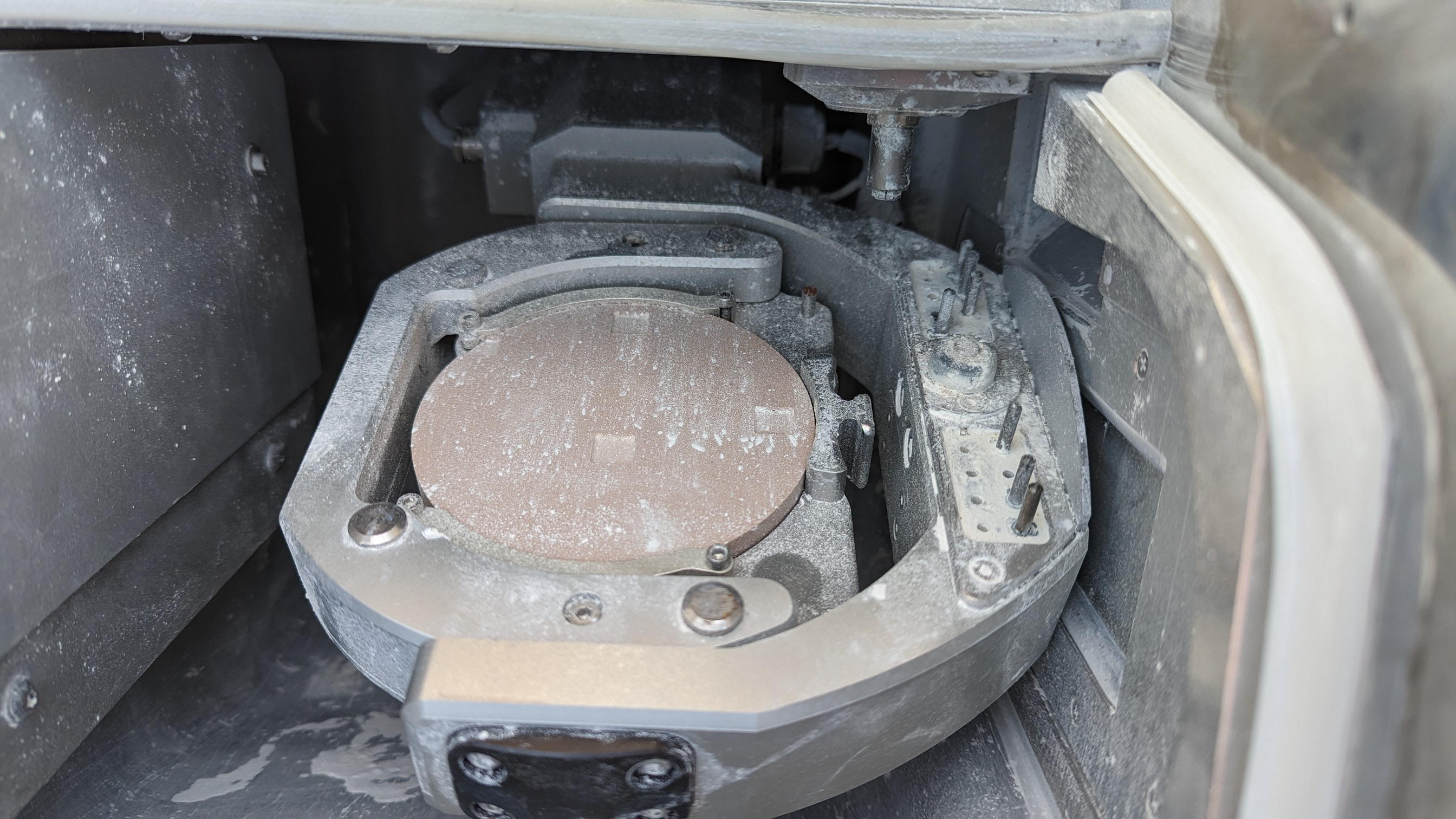
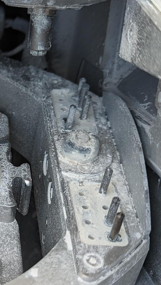
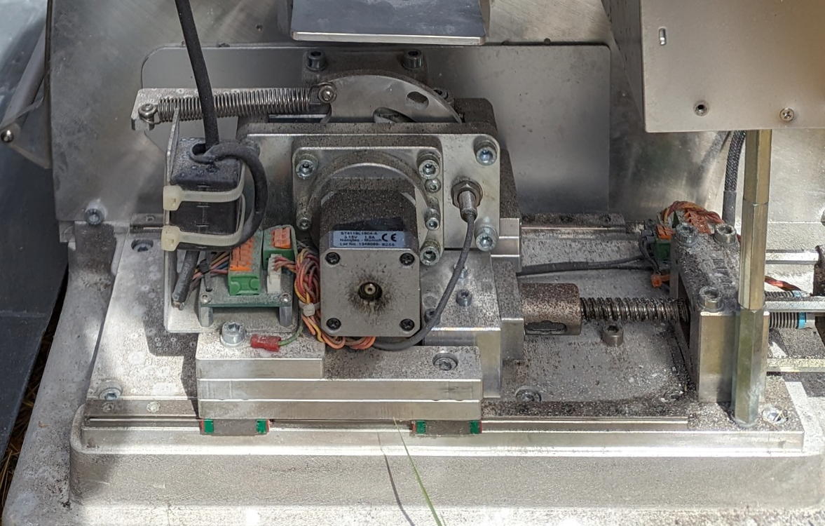
I'm going to either forego the tool changer or re-work it as a 6 or 8 tool instead of 16. Tools with that depth-gauge circlip are way out of my budget, and I think that's integral to operating it as a 16-tool magazine. The spindle, however. It's an VHF-branded SFS 300P. Neither SFS nor VHF publish any pinout, voltage requirement, control frequency range or any useful build info. The motor control daughterboard gives me the pinout for the motor, but I don't have the electronics fu to get any farther than that.
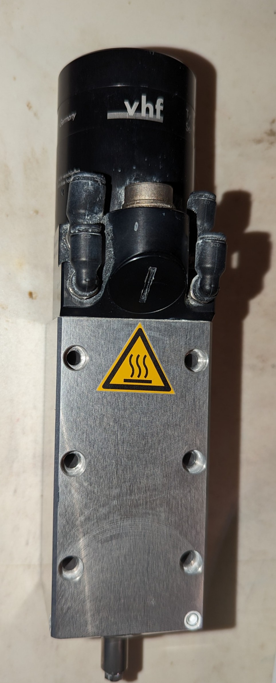


So, my questions are:1) Does anyone here have knowledge or experience with this particular machine? A service manual or any maintenance information would be miraculous.2) Same question for the spindle assembly. I do have the pressure & flow specs for the air seal and chuck controls, but working out the input voltage and speed control are out of my depth.3) Assuming the absence of model-specific details, how should I go about reverse-engineering the motor? I have multimeters and oscilloscope.
Thanks!
Doc
The motion part is pretty straightforward. Open loop NEMA17 steppers with ball screws, I don't expect any problem controlling the motion. I might at some point build a bigger frame but for now, I'm looking at a working envelope of about 4" x 3.5" x 3" plus I think 90 degrees on A and 360 on B.
I'm going to either forego the tool changer or re-work it as a 6 or 8 tool instead of 16. Tools with that depth-gauge circlip are way out of my budget, and I think that's integral to operating it as a 16-tool magazine. The spindle, however. It's an VHF-branded SFS 300P. Neither SFS nor VHF publish any pinout, voltage requirement, control frequency range or any useful build info. The motor control daughterboard gives me the pinout for the motor, but I don't have the electronics fu to get any farther than that.
So, my questions are:1) Does anyone here have knowledge or experience with this particular machine? A service manual or any maintenance information would be miraculous.2) Same question for the spindle assembly. I do have the pressure & flow specs for the air seal and chuck controls, but working out the input voltage and speed control are out of my depth.3) Assuming the absence of model-specific details, how should I go about reverse-engineering the motor? I have multimeters and oscilloscope.
Thanks!
Doc
01 Sep 2023 00:28
Replied by spumco on topic Mesa board with support for DROmagnetic encoders
Mesa board with support for DROmagnetic encoders
Category: Driver Boards
SLOW DOWN!
First - there's a 7I85 and a 7i85S. The difference is:
The 7i96S + 7i85S is a great combo... it's what I'm using in my current lathe project. But I had to add more IO (lots) and now I'm out of serial expansion ports. No regrets, but I'm not expanding any further without swapping out a board.
Second - there are numerous threads in this forum about closing the loop back to LCNC with steppers. The problem is searching the forum is a bit difficult... but get used to it. Read as much as you can. Maybe search for "loop" and limit it to search titles only.
One of the users here (Hakan) posted a number of nice videos about closing the loop with steppers (and later servos) on you tube. Search YT for some good overviews.
More importantly... dealing with closed loop is WAY down the road you're about to travel. The LCNC learning curve is steep, especially if you aren't a 'computer person' (like me). There are multiple concepts you'll need to become familiar with to get an open loop system sorted out. Once it's happy, then you can close the loop and sort out the tuning.
Read the LCNC online manual.
Read about HAL and INI files.
Read about user interfaces (GUI's)
Search YT for "Feral Engineer" and watch EVERY linuxcnc video he published.
Come back when your brain hurts.

First - there's a 7I85 and a 7i85S. The difference is:
- 7i85
- 4 encoder inputs
- 5 serial expansion ports
- 7i85S
- 4 step & direction outputs (more axes)
- 4 encoder inputs
- 1 serial expansion port
- Does the 7i96S and one of the two 7i85's have all the IO you need?
- What's your spindle?
- How many IO points do you have (or want)?
- What sensors do you have? PNP? NPN? Switches? What voltage?
- Do you want a tool changer?
- Do you plan on a couple - or a bunch - of physical control buttons for the operator?
- How much room do you have in your electrical cabinet?
The 7i96S + 7i85S is a great combo... it's what I'm using in my current lathe project. But I had to add more IO (lots) and now I'm out of serial expansion ports. No regrets, but I'm not expanding any further without swapping out a board.
Second - there are numerous threads in this forum about closing the loop back to LCNC with steppers. The problem is searching the forum is a bit difficult... but get used to it. Read as much as you can. Maybe search for "loop" and limit it to search titles only.
One of the users here (Hakan) posted a number of nice videos about closing the loop with steppers (and later servos) on you tube. Search YT for some good overviews.
More importantly... dealing with closed loop is WAY down the road you're about to travel. The LCNC learning curve is steep, especially if you aren't a 'computer person' (like me). There are multiple concepts you'll need to become familiar with to get an open loop system sorted out. Once it's happy, then you can close the loop and sort out the tuning.
Read the LCNC online manual.
Read about HAL and INI files.
Read about user interfaces (GUI's)
Search YT for "Feral Engineer" and watch EVERY linuxcnc video he published.
Come back when your brain hurts.
30 Aug 2023 10:02
7i96S and Emergency / E-Stop was created by kevin_allein
7i96S and Emergency / E-Stop
Category: Driver Boards
Hi all, I have a CNC lathe, that I used to run with MACH4 and the Ethernet Smooth Stepper and want to convert it to LinuxCNC now.
I connected the Ethernet Smooth Stepper to parallel breakout boards from Langenfeld for Step / Dir ( www.pro-tos.de/shop/Interface/Parallel-Interface-12-5.html ) and also their analog spindle drive ( www.pro-tos.de/shop/Interface/Frequenzum...euerung-0---10V.html )
This had the benefit, that the signal from the E-Stop would directly stop both the spindle as well as all Steppers immediately without needing to go through the PC (in case of any problems)
I now ordered a MESA 7i96S (basically the only thing I could find). This would obviously not require the Langenfeld cards anymore, but how can I get the same functionality with direct E-Stop not relying on LinuxCNC ?
To use the P1 connector I would need a special bit file mapping Step and Dir to the correct pins of that header. But once I need a special bit file, I could also implement the logic in the FPGA to gat everything with an E-Stop signal.
So do I need to write a custom bit file ? Is there a getting started guide ? There seems to be lots of info on the web about creating bit files for the XILINX FPGAs used before, but I read, that the 7i96S is using a different FPGA.
Thanks for any help
29 Aug 2023 17:08 - 29 Aug 2023 18:02
Fast pulse for stepper with EL2202 was created by JoBoCNC
Fast pulse for stepper with EL2202
Category: EtherCAT
Hello,
I would like to replace my parallel port system with Ethercat. My existing system uses closed loop stepper drivers with parallel port.
My idea was to use a fast Beckhoff module for the stepper pulses. So I bought the EL2202 module.
To test the setup, I added the Ethercat commands for Y-axis to my previous configuration files.
At low speed everything works fine. But at higher speed the stepper loses steps.
The other axes with the parallel port work fine at these speeds.
So I think that the EL2202 is not generating the pulses fast enough.
In my opinion, with my config it is at least possible to generate the same speed as the parallel port axis.
Any suggestion what i can try? Think it is a configuration issue. So here my config files.
Thank you very much!
Here my .hal
.ini:
And my Ethercat config file:
I would like to replace my parallel port system with Ethercat. My existing system uses closed loop stepper drivers with parallel port.
My idea was to use a fast Beckhoff module for the stepper pulses. So I bought the EL2202 module.
To test the setup, I added the Ethercat commands for Y-axis to my previous configuration files.
At low speed everything works fine. But at higher speed the stepper loses steps.
The other axes with the parallel port work fine at these speeds.
So I think that the EL2202 is not generating the pulses fast enough.
In my opinion, with my config it is at least possible to generate the same speed as the parallel port axis.
Any suggestion what i can try? Think it is a configuration issue. So here my config files.
Thank you very much!
Here my .hal
# Generated by stepconf 1.1 at Sat Sep  3 11:45:09 2022
# Änderungen an dieser Datei werden beim nächsten
# Aufruf von stepconf überschrieben.

#loadrt trivkins

loadusr -W lcec_conf ethercat-conf.xml
loadrt lcec

loadrt [KINS]KINEMATICS
loadrt [EMCMOT]EMCMOT base_period_nsec=[EMCMOT]BASE_PERIOD servo_period_nsec=[EMCMOT]SERVO_PERIOD num_joints=[KINS]JOINTS

loadrt hal_parport cfg="0 out"
setp parport.0.reset-time 50 #5000
loadrt stepgen step_type=0,0,0,0
loadrt pwmgen output_type=1 #1


addf stepgen.capture-position servo-thread
addf motion-command-handler servo-thread
addf motion-controller servo-thread
addf stepgen.update-freq servo-thread #servo
addf pwmgen.update servo-thread


addf lcec.read-all base-thread #servo
#addf lcec.write-all servo-thread

addf parport.0.read base-thread
addf stepgen.make-pulses base-thread
addf pwmgen.make-pulses base-thread
addf parport.0.write base-thread
addf parport.0.reset base-thread
addf lcec.write-all base-thread    #testservo


net spindle-cmd-rpm => pwmgen.0.value
net spindle-on <= spindle.0.on => pwmgen.0.enable
net spindle-pwm <= pwmgen.0.pwm
setp pwmgen.0.pwm-freq 8000.0
setp pwmgen.0.scale 24000
setp pwmgen.0.offset 0
setp pwmgen.0.dither-pwm true
net spindle-cmd-rpm     <= spindle.0.speed-out
net spindle-cmd-rpm-abs <= spindle.0.speed-out-abs
net spindle-cmd-rps     <= spindle.0.speed-out-rps
net spindle-cmd-rps-abs <= spindle.0.speed-out-rps-abs
net spindle-at-speed    => spindle.0.at-speed
net dout-00 <= motion.digital-out-00

setp parport.0.pin-01-out-invert 1
net spindle-pwm     => parport.0.pin-01-out
setp parport.0.pin-02-out-invert 1
net zstep           => parport.0.pin-02-out
setp parport.0.pin-02-out-reset 1
setp parport.0.pin-03-out-invert 1
net zdir            => parport.0.pin-03-out

#setp parport.0.pin-04-out-invert 1
#net ystep           => parport.0.pin-04-out
net ystep           => lcec.0.1.dout-1  #changed to ethercat
#setp parport.0.pin-04-out-reset 1
#setp lcec.0.1.dout-1-reset 1

setp parport.0.pin-05-out-invert 1
net ydir            => parport.0.pin-05-out
setp parport.0.pin-06-out-invert 1
net xstep           => parport.0.pin-06-out
setp parport.0.pin-06-out-reset 1
net xdir            => parport.0.pin-07-out
setp parport.0.pin-08-out-invert 1
net x2step           => parport.0.pin-08-out
setp parport.0.pin-08-out-reset 1
net x2dir            => parport.0.pin-09-out

net xenable         => parport.0.pin-14-out
net dout-00         => parport.0.pin-16-out
net spindle-on      => parport.0.pin-17-out
net home-z          <= parport.0.pin-10-in-not
net home-y          <= parport.0.pin-11-in-not
net home-x          <= parport.0.pin-13-in-not
net home-x2          <= parport.0.pin-12-in-not
net estop-ext       <= parport.0.pin-15-in-not


setp stepgen.0.position-scale [JOINT_0]SCALE
setp stepgen.0.steplen 1
setp stepgen.0.stepspace 0
setp stepgen.0.dirhold 44000
setp stepgen.0.dirsetup 44000
setp stepgen.0.maxaccel [JOINT_0]STEPGEN_MAXACCEL
net xpos-cmd joint.0.motor-pos-cmd => stepgen.0.position-cmd
net xpos-fb stepgen.0.position-fb => joint.0.motor-pos-fb
net xstep <= stepgen.0.step
net xdir <= stepgen.0.dir
net xenable joint.0.amp-enable-out => stepgen.0.enable
net home-x => joint.0.home-sw-in

setp stepgen.1.position-scale [JOINT_1]SCALE
setp stepgen.1.steplen 1
setp stepgen.1.stepspace 0
setp stepgen.1.dirhold 27000
setp stepgen.1.dirsetup 27000
setp stepgen.1.maxaccel [JOINT_1]STEPGEN_MAXACCEL
net x2pos-cmd joint.1.motor-pos-cmd => stepgen.1.position-cmd
net x2pos-fb stepgen.1.position-fb => joint.1.motor-pos-fb
net x2step <= stepgen.1.step
net x2dir <= stepgen.1.dir
net x2enable joint.1.amp-enable-out => stepgen.1.enable
net home-x2 => joint.1.home-sw-in

setp stepgen.2.position-scale [JOINT_2]SCALE
setp stepgen.2.steplen 1 #1
setp stepgen.2.stepspace 0 #0
setp stepgen.2.dirhold 35000 #27000
setp stepgen.2.dirsetup 35000
setp stepgen.2.maxaccel [JOINT_2]STEPGEN_MAXACCEL
net ypos-cmd joint.2.motor-pos-cmd => stepgen.2.position-cmd
net ypos-fb stepgen.2.position-fb => joint.2.motor-pos-fb
net ystep <= stepgen.2.step
net ydir <= stepgen.2.dir
net yenable joint.2.amp-enable-out => stepgen.2.enable
net home-y => joint.2.home-sw-in

setp stepgen.3.position-scale [JOINT_3]SCALE
setp stepgen.3.steplen 1
setp stepgen.3.stepspace 0
setp stepgen.3.dirhold 27000
setp stepgen.3.dirsetup 27000
setp stepgen.3.maxaccel [JOINT_3]STEPGEN_MAXACCEL
net zpos-cmd joint.3.motor-pos-cmd => stepgen.3.position-cmd
net zpos-fb stepgen.3.position-fb => joint.3.motor-pos-fb
net zstep <= stepgen.3.step
net zdir <= stepgen.3.dir
net zenable joint.3.amp-enable-out => stepgen.3.enable
net home-z => joint.3.home-sw-in

#setp stepgen.3.position-scale [AXIS_Z]SCALE
#setp stepgen.3.steplen 1
#setp stepgen.3.stepspace 0
#setp stepgen.3.dirhold 27000
#setp stepgen.3.dirsetup 27000
#setp stepgen.3.maxaccel [AXIS_3]STEPGEN_MAXACCEL
#net apos-cmd joint.3.motor-pos-cmd => stepgen.3.position-cmd
#net apos-fb stepgen.3.position-fb => joint.3.motor-pos-fb
#net astep <= stepgen.3.step
#net adir <= stepgen.3.dir
#net aenable joint.3.amp-enable-out => stepgen.3.enable
#net home-a => joint.3.home-sw-in

net estop-out <= iocontrol.0.user-enable-out
net estop-ext => iocontrol.0.emc-enable-in

loadusr -W hal_manualtoolchange
net tool-change iocontrol.0.tool-change => hal_manualtoolchange.change
net tool-changed iocontrol.0.tool-changed <= hal_manualtoolchange.changed
net tool-number iocontrol.0.tool-prep-number => hal_manualtoolchange.number
net tool-prepare-loopback iocontrol.0.tool-prepare => iocontrol.0.tool-prepared
.ini:
# This config file was created 2022-09-09 17:56:09.071663 by the update_ini script
# The original config files may be found in the /home/jobo/linuxcnc/configs/Meine-Maschine/Meine-Maschine.old directory

# Generated by stepconf 1.1 at Sat Sep  3 11:45:09 2022
# Änderungen an dieser Datei werden beim nächsten
# Aufruf von stepconf überschrieben.

[EMC]
# The version string for this INI file.
VERSION = 1.1

MACHINE = Meine-Maschine
DEBUG = 0

[DISPLAY]
DISPLAY = axis
EDITOR = gedit
POSITION_OFFSET = RELATIVE
POSITION_FEEDBACK = ACTUAL
ARCDIVISION = 64
GRIDS = 10mm 20mm 50mm 100mm 1in 2in 5in 10in
MAX_FEED_OVERRIDE = 1.2
MIN_SPINDLE_OVERRIDE = 0.5
MAX_SPINDLE_OVERRIDE = 1.2
DEFAULT_LINEAR_VELOCITY = 30.00
MIN_LINEAR_VELOCITY = 0
MAX_LINEAR_VELOCITY = 750.00
DEFAULT_ANGULAR_VELOCITY = 10
MIN_ANGULAR_VELOCITY = 0
MAX_ANGULAR_VELOCITY = 50.00
INTRO_GRAPHIC = linuxcnc.gif
INTRO_TIME = 2
PROGRAM_PREFIX = /home/jobo/linuxcnc/nc_files
INCREMENTS = 5mm 1mm .5mm .1mm .05mm .01mm .005mm
PYVCP = custompanel.xml
#GEOMETRY = xyz

[KINS]
JOINTS = 4
KINEMATICS = trivkins coordinates=XXYZ

[FILTER]
PROGRAM_EXTENSION = .png,.gif,.jpg Greyscale Depth Image
PROGRAM_EXTENSION = .py Python Script
png = image-to-gcode
gif = image-to-gcode
jpg = image-to-gcode
py = python

[RS274NGC]

PARAMETER_FILE = linuxcnc.var

[EMCMOT]

EMCMOT = motmod
COMM_TIMEOUT = 1.0
BASE_PERIOD = 30000
SERVO_PERIOD = 1050000
#120000

[TASK]
TASK = milltask
CYCLE_TIME = 0.001

[HAL]
HALFILE = Meine-Maschine.hal
HALFILE = custom.hal
POSTGUI_HALFILE = custom_postgui.hal

[HALUI]
#No Content


[TRAJ]
COORDINATES = X X Y Z
LINEAR_UNITS = mm
ANGULAR_UNITS = degree
DEFAULT_LINEAR_VELOCITY = 10
MAX_LINEAR_VELOCITY = 750.00
#NO_FORCE_HOMING = 0

[EMCIO]
EMCIO = io
CYCLE_TIME = 0.100
TOOL_TABLE = tool.tbl


[AXIS_X]
MIN_LIMIT = -0.001
MAX_LIMIT = 572.0
MAX_VELOCITY = 750
MAX_ACCELERATION = 750.0

[JOINT_0]
TYPE = LINEAR
HOME = 0.0
MIN_LIMIT = -0.001
MAX_LIMIT = 572.0
MAX_VELOCITY = 750
MAX_ACCELERATION = 750.0
STEPGEN_MAXACCEL = 937.5
SCALE = 320.0
FERROR = 1
MIN_FERROR = .25
#HOME_OFFSET = 0.000000
#HOME_SEARCH_VEL = -10.000000
#HOME_LATCH_VEL = -0.2
#HOME_SEQUENCE = 1

HOME_OFFSET = -0.800000
HOME_SEARCH_VEL = -12.000000
HOME_LATCH_VEL = -0.2
HOME_SEQUENCE = -1
HOME_FINAL_VEL = 5
HOME_USE_INDEX = NO

[JOINT_1]
TYPE = LINEAR
HOME = 0.0
MIN_LIMIT = -0.001
MAX_LIMIT = 572.0
MAX_VELOCITY = 750
MAX_ACCELERATION = 750.0
STEPGEN_MAXACCEL = 937.5
SCALE = 320.0
FERROR = 1
MIN_FERROR = .25
#HOME_OFFSET = 0.000000
#HOME_SEARCH_VEL = -10.000000
#HOME_LATCH_VEL = -0.2
#HOME_SEQUENCE = 1

HOME_OFFSET = -0.600000
HOME_SEARCH_VEL = -12.000000
HOME_LATCH_VEL = -0.2
HOME_SEQUENCE = -1
HOME_FINAL_VEL = 5
HOME_USE_INDEX = NO

[AXIS_Y]
MIN_LIMIT = 0.0
MAX_LIMIT = 480.001
MAX_VELOCITY = 75
MAX_ACCELERATION = 750.0

[JOINT_2]

TYPE = LINEAR
HOME = 480.0
MAX_VELOCITY = 75
MAX_ACCELERATION = 750.0
STEPGEN_MAXACCEL = 937.5
SCALE = 320.0
FERROR = 1
MIN_FERROR = .25
MIN_LIMIT = -0.001
MAX_LIMIT = 480.001
HOME_OFFSET = 480.000000
HOME_SEARCH_VEL = 12.000000
HOME_LATCH_VEL = 0.2
HOME_SEQUENCE = 2

[AXIS_Z]
MIN_LIMIT = -250.00
MAX_LIMIT = 0.001
MAX_VELOCITY = 50
MAX_ACCELERATION = 750.0

[JOINT_3]
TYPE = LINEAR
HOME = 0.0
MAX_VELOCITY = 50
MAX_ACCELERATION = 750.0
STEPGEN_MAXACCEL = 937.5
SCALE = 320.0
FERROR = 1
MIN_FERROR = .25
MIN_LIMIT = -250.00
MAX_LIMIT = 0.001
HOME_OFFSET = 0.000000
HOME_SEARCH_VEL = 12.000000
HOME_LATCH_VEL = 0.2
HOME_SEQUENCE = 0
And my Ethercat config file:
<masters>
<master idx="0" appTimePeriod="30000" refClockSyncCycles="5">
<slave idx="0" type="EK1100"/>
<slave idx="1" type="EL2202"/>
<slave idx="2" type="EL1819"/>

</master>
</masters>
27 Aug 2023 21:05
5i25 and 7i76 issue was created by HenrikWJ
5i25 and 7i76 issue
Category: General LinuxCNC Questions
I have installed 5i25 and 7i76. Power is fed from 5i25. 7i76 is connected to a single iHSV57 just to make it work.
Pncconf is started but does not show the drop down for selecting boards:
I would like to insert a screenshot but that does not appear to be possible. You will have to take my word for it: no drop down box.
I get to the configuration page where I select:
5i25 - internal data
7i76x2 with one 7i76
I then define 4 axis's with all default parameters.
When I load the file i get this in the report:
./init3.hal:55: parameter or pin 'hm2_5i25.0.stepgen.00.dirsetup' not found
What is wrong here?
Is the the pin not not found hardware or something in the firmware?
I am new at this, and have my sincere apologies for the naive approach!
Any help is much appreciated.
KR
Henrik
The report and other files generated:
Error report created by /usr/lib/tcltk/linuxcnc/show_errors.tcl:
Print file information:
RUN_IN_PLACE=no
LINUXCNC_DIR=
LINUXCNC_BIN_DIR=/usr/bin
LINUXCNC_TCL_DIR=/usr/lib/tcltk/linuxcnc
LINUXCNC_SCRIPT_DIR=
LINUXCNC_RTLIB_DIR=/usr/lib/linuxcnc/modules
LINUXCNC_CONFIG_DIR=
LINUXCNC_LANG_DIR=/usr/lib/tcltk/linuxcnc/msgs
INIVAR=inivar
HALCMD=halcmd
LINUXCNC_EMCSH=/usr/bin/wish8.6
LINUXCNC - 2.8.4-1-gb7824717b
Machine configuration directory is '/home/hwj/linuxcnc/configs/init3'
Machine configuration file is 'init3.ini'
INIFILE=/home/hwj/linuxcnc/configs/init3/init3.ini
VERSION=1.1
PARAMETER_FILE=linuxcnc.var
TASK=milltask
HALUI=halui
DISPLAY=axis
COORDINATES=XYZ
KINEMATICS=trivkins coordinates=XYZ
Starting LinuxCNC...
Starting LinuxCNC server program: linuxcncsvr
Loading Real Time OS, RTAPI, and HAL_LIB modules
Starting LinuxCNC IO program: io
Starting HAL User Interface program: halui
Found file(REL): ./init3.hal
Shutting down and cleaning up LinuxCNC...
Running HAL shutdown script
hm2: loading Mesa HostMot2 driver version 0.15
hm2_pci: loading Mesa AnyIO HostMot2 driver version 0.7
hm2_pci: discovered 5i25 at 0000:04:05.0
hm2/hm2_5i25.0: Low Level init 0.15
hm2/hm2_5i25.0: Smart Serial Firmware Version 43
hm2/hm2_5i25.0: 34 I/O Pins used:
hm2/hm2_5i25.0: IO Pin 000 (P3-01): IOPort
hm2/hm2_5i25.0: IO Pin 001 (P3-14): IOPort
hm2/hm2_5i25.0: IO Pin 002 (P3-02): IOPort
hm2/hm2_5i25.0: IO Pin 003 (P3-15): IOPort
hm2/hm2_5i25.0: IO Pin 004 (P3-03): IOPort
hm2/hm2_5i25.0: IO Pin 005 (P3-16): IOPort
hm2/hm2_5i25.0: IO Pin 006 (P3-04): IOPort
hm2/hm2_5i25.0: IO Pin 007 (P3-17): Muxed Encoder Select #0, pin Mux Select 0 (Output)
hm2/hm2_5i25.0: IO Pin 008 (P3-05): Muxed Encoder #0, pin Muxed A (Input)
hm2/hm2_5i25.0: IO Pin 009 (P3-06): Muxed Encoder #0, pin Muxed B (Input)
hm2/hm2_5i25.0: IO Pin 010 (P3-07): Muxed Encoder #0, pin Muxed Index (Input)
hm2/hm2_5i25.0: IO Pin 011 (P3-08): IOPort
hm2/hm2_5i25.0: IO Pin 012 (P3-09): IOPort
hm2/hm2_5i25.0: IO Pin 013 (P3-10): IOPort
hm2/hm2_5i25.0: IO Pin 014 (P3-11): IOPort
hm2/hm2_5i25.0: IO Pin 015 (P3-12): IOPort
hm2/hm2_5i25.0: IO Pin 016 (P3-13): IOPort
hm2/hm2_5i25.0: IO Pin 017 (P2-01): IOPort
hm2/hm2_5i25.0: IO Pin 018 (P2-14): IOPort
hm2/hm2_5i25.0: IO Pin 019 (P2-02): IOPort
hm2/hm2_5i25.0: IO Pin 020 (P2-15): IOPort
hm2/hm2_5i25.0: IO Pin 021 (P2-03): IOPort
hm2/hm2_5i25.0: IO Pin 022 (P2-16): IOPort
hm2/hm2_5i25.0: IO Pin 023 (P2-04): IOPort
hm2/hm2_5i25.0: IO Pin 024 (P2-17): IOPort
hm2/hm2_5i25.0: IO Pin 025 (P2-05): IOPort
hm2/hm2_5i25.0: IO Pin 026 (P2-06): IOPort
hm2/hm2_5i25.0: IO Pin 027 (P2-07): IOPort
hm2/hm2_5i25.0: IO Pin 028 (P2-08): IOPort
hm2/hm2_5i25.0: IO Pin 029 (P2-09): IOPort
hm2/hm2_5i25.0: IO Pin 030 (P2-10): IOPort
hm2/hm2_5i25.0: IO Pin 031 (P2-11): IOPort
hm2/hm2_5i25.0: IO Pin 032 (P2-12): IOPort
hm2/hm2_5i25.0: IO Pin 033 (P2-13): IOPort
hm2/hm2_5i25.0: registered
hm2_5i25.0: initialized AnyIO board at 0000:04:05.0
hm2_5i25.0: dropping AnyIO board at 0000:04:05.0
hm2/hm2_5i25.0: unregistered
hm2_pci: driver unloaded
hm2: unloading
Removing HAL_LIB, RTAPI, and Real Time OS modules
Removing NML shared memory segments
Debug file information:
Note: Using POSIX realtime
./init3.hal:55: parameter or pin 'hm2_5i25.0.stepgen.00.dirsetup' not found
1727
Stopping realtime threads
Unloading hal components
RTAPI_PCI: Unmapped 65536 bytes at 0x7fbfd5ed0000
Note: Using POSIX realtime
Info report created by linuxcnc_info:
The file: /tmp/linuxcnc_info.txt
can be posted to a forum or a web site like:
pastebin.com
in order to provide information about the linuxcnc
system and configuration.
Date: Sun 27 Aug 2023 10:53:47 PM CEST
UTC Date: Sun 27 Aug 2023 08:53:47 PM UTC
this program: /usr/bin/linuxcnc_info
uptime: 22:53:47 up 32 min, 1 user, load average: 0.50, 0.44, 0.66
lsb_release -sa: Debian Debian GNU/Linux 10 (buster) 10 buster
which linuxcnc: /usr/bin/linuxcnc
pwd: /home/hwj/linuxcnc/configs/init3
USER: hwj
LOGNAME: hwj
HOME: /home/hwj
EDITOR:
VISUAL:
LANGUAGE: en_US:en
TERM: dumb
COLORTERM:
DISPLAY: :0.0
DESKTOP: xfce
display size: 1920x1080 pixels (508x285 millimeters)
PATH: /usr/bin:/home/hwj/linuxcnc/configs/init3/bin:/usr/bin:/usr/local/bin:/usr/bin:/bin:/usr/local/games:/usr/games
uname items:
nodename -n: LinuxCNC
kernel-name -s: Linux
kernel-vers -v: #1 SMP PREEMPT RT Debian 4.19.249-2 (2022-06-30)
machine -m: x86_64
processor -p: unknown
platform -i: unknown
oper system -o: GNU/Linux
/proc items:
cmdline: BOOT_IMAGE=/boot/vmlinuz-4.19.0-21-rt-amd64 root=UUID=646dfacc-5136-478c-833a-a7febaa524cd ro quiet
model name: AMD FX(tm)-4130 Quad-Core Processor
cores: 2
cpu MHz: 1929.439
parport:
serial: 0000-0000 : serial
Versions:
gcc: gcc (Debian 8.3.0-6) 8.3.0
python: Python 2.7.16
git: not_in_PATH
git commit: NA
tcl: 8.6
tk: 8.6
glade: not_in_PATH
glade-gtk2: not_in_PATH
linuxcnc_var all:
LINUXCNCVERSION: 2.8.4-1-gb7824717b
LINUXCNC_AUX_GLADEVCP: /usr/share/linuxcnc/aux_gladevcp
LINUXCNC_AUX_EXAMPLES: /usr/share/linuxcnc/aux_examples
REALTIME: /etc/init.d/realtime
RTS: uspace
HALLIB_DIR: /usr/share/linuxcnc/hallib
dpkg -l '*linuxcnc*':
Desired=Unknown/Install/Remove/Purge/Hold
| Status=Not/Inst/Conf-files/Unpacked/halF-conf/Half-inst/trig-aWait/Trig-pend
|/ Err?=(none)/Reinst-required (Status,Err: uppercase=bad)
||/ Name Version Architecture Description
+++-===================-====================-============-=====================================================================
un linuxcnc <none> <none> (no description available)
un linuxcnc-dev <none> <none> (no description available)
un linuxcnc-doc <none> <none> (no description available)
ii linuxcnc-doc-en 1:2.8.4.1.gb7824717b all motion controller for CNC machines and robots (English documentation)
ii linuxcnc-doc-es 1:2.8.4.1.gb7824717b all controlador de movimiento para máquinas CNC y robots (Español).
ii linuxcnc-doc-fr 1:2.8.4.1.gb7824717b all motion controller for CNC machines and robots (French documentation)
un linuxcnc-sim <none> <none> (no description available)
un linuxcnc-sim-dev <none> <none> (no description available)
ii linuxcnc-uspace 1:2.8.4.1.gb7824717b amd64 motion controller for CNC machines and robots
ii linuxcnc-uspace-dev 1:2.8.4.1.gb7824717b amd64 PC based motion controller for real-time Linux
The hal file is:
# Generated by PNCconf at Sun Aug 27 22:52:59 2023
# Using LinuxCNC version: 2.8
# If you make changes to this file, they will be
# overwritten when you run PNCconf again
loadrt [KINS]KINEMATICS
loadrt [EMCMOT]EMCMOT servo_period_nsec=[EMCMOT]SERVO_PERIOD num_joints=[KINS]JOINTS
loadrt hostmot2
loadrt hm2_pci config="num_encoders=1 num_pwmgens=0 num_stepgens=5 sserial_port_0=00xxxx"
setp hm2_5i25.0.watchdog.timeout_ns 5000000
loadrt pid names=pid.x,pid.y,pid.z,pid.s
addf hm2_5i25.0.read servo-thread
addf motion-command-handler servo-thread
addf motion-controller servo-thread
addf pid.x.do-pid-calcs servo-thread
addf pid.y.do-pid-calcs servo-thread
addf pid.z.do-pid-calcs servo-thread
addf pid.s.do-pid-calcs servo-thread
addf hm2_5i25.0.write servo-thread
# external output signals
# external input signals
#*******************
# AXIS X JOINT 0
#*******************
setp pid.x.Pgain [JOINT_0]P
setp pid.x.Igain [JOINT_0]I
setp pid.x.Dgain [JOINT_0]D
setp pid.x.bias [JOINT_0]BIAS
setp pid.x.FF0 [JOINT_0]FF0
setp pid.x.FF1 [JOINT_0]FF1
setp pid.x.FF2 [JOINT_0]FF2
setp pid.x.deadband [JOINT_0]DEADBAND
setp pid.x.maxoutput [JOINT_0]MAX_OUTPUT
setp pid.x.error-previous-target true
# This setting is to limit bogus stepgen
# velocity corrections caused by position
# feedback sample time jitter.
setp pid.x.maxerror 0.000500
net x-index-enable => pid.x.index-enable
net x-enable => pid.x.enable
net x-pos-cmd => pid.x.command
net x-pos-fb => pid.x.feedback
net x-output <= pid.x.output
# Step Gen signals/setup
setp hm2_5i25.0.stepgen.00.dirsetup [JOINT_0]DIRSETUP
setp hm2_5i25.0.stepgen.00.dirhold [JOINT_0]DIRHOLD
setp hm2_5i25.0.stepgen.00.steplen [JOINT_0]STEPLEN
setp hm2_5i25.0.stepgen.00.stepspace [JOINT_0]STEPSPACE
setp hm2_5i25.0.stepgen.00.position-scale [JOINT_0]STEP_SCALE
setp hm2_5i25.0.stepgen.00.step_type 0
setp hm2_5i25.0.stepgen.00.control-type 1
setp hm2_5i25.0.stepgen.00.maxaccel [JOINT_0]STEPGEN_MAXACCEL
setp hm2_5i25.0.stepgen.00.maxvel [JOINT_0]STEPGEN_MAXVEL
# ---closedloop stepper signals---
net x-pos-cmd <= joint.0.motor-pos-cmd
net x-vel-cmd <= joint.0.vel-cmd
net x-output => hm2_5i25.0.stepgen.00.velocity-cmd
net x-pos-fb <= hm2_5i25.0.stepgen.00.position-fb
net x-pos-fb => joint.0.motor-pos-fb
net x-enable <= joint.0.amp-enable-out
net x-enable => hm2_5i25.0.stepgen.00.enable
# ---setup home / limit switch signals---
net x-home-sw => joint.0.home-sw-in
net x-neg-limit => joint.0.neg-lim-sw-in
net x-pos-limit => joint.0.pos-lim-sw-in
#*******************
# AXIS Y JOINT 1
#*******************
setp pid.y.Pgain [JOINT_1]P
setp pid.y.Igain [JOINT_1]I
setp pid.y.Dgain [JOINT_1]D
setp pid.y.bias [JOINT_1]BIAS
setp pid.y.FF0 [JOINT_1]FF0
setp pid.y.FF1 [JOINT_1]FF1
setp pid.y.FF2 [JOINT_1]FF2
setp pid.y.deadband [JOINT_1]DEADBAND
setp pid.y.maxoutput [JOINT_1]MAX_OUTPUT
setp pid.y.error-previous-target true
# This setting is to limit bogus stepgen
# velocity corrections caused by position
# feedback sample time jitter.
setp pid.y.maxerror 0.000500
net y-index-enable => pid.y.index-enable
net y-enable => pid.y.enable
net y-pos-cmd => pid.y.command
net y-pos-fb => pid.y.feedback
net y-output <= pid.y.output
# Step Gen signals/setup
setp hm2_5i25.0.stepgen.01.dirsetup [JOINT_1]DIRSETUP
setp hm2_5i25.0.stepgen.01.dirhold [JOINT_1]DIRHOLD
setp hm2_5i25.0.stepgen.01.steplen [JOINT_1]STEPLEN
setp hm2_5i25.0.stepgen.01.stepspace [JOINT_1]STEPSPACE
setp hm2_5i25.0.stepgen.01.position-scale [JOINT_1]STEP_SCALE
setp hm2_5i25.0.stepgen.01.step_type 0
setp hm2_5i25.0.stepgen.01.control-type 1
setp hm2_5i25.0.stepgen.01.maxaccel [JOINT_1]STEPGEN_MAXACCEL
setp hm2_5i25.0.stepgen.01.maxvel [JOINT_1]STEPGEN_MAXVEL
# ---closedloop stepper signals---
net y-pos-cmd <= joint.1.motor-pos-cmd
net y-vel-cmd <= joint.1.vel-cmd
net y-output => hm2_5i25.0.stepgen.01.velocity-cmd
net y-pos-fb <= hm2_5i25.0.stepgen.01.position-fb
net y-pos-fb => joint.1.motor-pos-fb
net y-enable <= joint.1.amp-enable-out
net y-enable => hm2_5i25.0.stepgen.01.enable
# ---setup home / limit switch signals---
net y-home-sw => joint.1.home-sw-in
net y-neg-limit => joint.1.neg-lim-sw-in
net y-pos-limit => joint.1.pos-lim-sw-in
#*******************
# AXIS Z JOINT 2
#*******************
setp pid.z.Pgain [JOINT_2]P
setp pid.z.Igain [JOINT_2]I
setp pid.z.Dgain [JOINT_2]D
setp pid.z.bias [JOINT_2]BIAS
setp pid.z.FF0 [JOINT_2]FF0
setp pid.z.FF1 [JOINT_2]FF1
setp pid.z.FF2 [JOINT_2]FF2
setp pid.z.deadband [JOINT_2]DEADBAND
setp pid.z.maxoutput [JOINT_2]MAX_OUTPUT
setp pid.z.error-previous-target true
# This setting is to limit bogus stepgen
# velocity corrections caused by position
# feedback sample time jitter.
setp pid.z.maxerror 0.000500
net z-index-enable => pid.z.index-enable
net z-enable => pid.z.enable
net z-pos-cmd => pid.z.command
net z-pos-fb => pid.z.feedback
net z-output <= pid.z.output
# Step Gen signals/setup
setp hm2_5i25.0.stepgen.02.dirsetup [JOINT_2]DIRSETUP
setp hm2_5i25.0.stepgen.02.dirhold [JOINT_2]DIRHOLD
setp hm2_5i25.0.stepgen.02.steplen [JOINT_2]STEPLEN
setp hm2_5i25.0.stepgen.02.stepspace [JOINT_2]STEPSPACE
setp hm2_5i25.0.stepgen.02.position-scale [JOINT_2]STEP_SCALE
setp hm2_5i25.0.stepgen.02.step_type 0
setp hm2_5i25.0.stepgen.02.control-type 1
setp hm2_5i25.0.stepgen.02.maxaccel [JOINT_2]STEPGEN_MAXACCEL
setp hm2_5i25.0.stepgen.02.maxvel [JOINT_2]STEPGEN_MAXVEL
# ---closedloop stepper signals---
net z-pos-cmd <= joint.2.motor-pos-cmd
net z-vel-cmd <= joint.2.vel-cmd
net z-output => hm2_5i25.0.stepgen.02.velocity-cmd
net z-pos-fb <= hm2_5i25.0.stepgen.02.position-fb
net z-pos-fb => joint.2.motor-pos-fb
net z-enable <= joint.2.amp-enable-out
net z-enable => hm2_5i25.0.stepgen.02.enable
# ---setup home / limit switch signals---
net z-home-sw => joint.2.home-sw-in
net z-neg-limit => joint.2.neg-lim-sw-in
net z-pos-limit => joint.2.pos-lim-sw-in
#*******************
# SPINDLE
#*******************
setp pid.s.Pgain [SPINDLE_0]P
setp pid.s.Igain [SPINDLE_0]I
setp pid.s.Dgain [SPINDLE_0]D
setp pid.s.bias [SPINDLE_0]BIAS
setp pid.s.FF0 [SPINDLE_0]FF0
setp pid.s.FF1 [SPINDLE_0]FF1
setp pid.s.FF2 [SPINDLE_0]FF2
setp pid.s.deadband [SPINDLE_0]DEADBAND
setp pid.s.maxoutput [SPINDLE_0]MAX_OUTPUT
setp pid.s.error-previous-target true
net spindle-index-enable => pid.s.index-enable
net spindle-enable => pid.s.enable
net spindle-vel-cmd-rpm => pid.s.command
net spindle-vel-fb-rpm => pid.s.feedback
net spindle-output <= pid.s.output
# ---setup spindle control signals---
net spindle-vel-cmd-rps <= spindle.0.speed-out-rps
net spindle-vel-cmd-rps-abs <= spindle.0.speed-out-rps-abs
net spindle-vel-cmd-rpm <= spindle.0.speed-out
net spindle-vel-cmd-rpm-abs <= spindle.0.speed-out-abs
net spindle-enable <= spindle.0.on
net spindle-cw <= spindle.0.forward
net spindle-ccw <= spindle.0.reverse
net spindle-brake <= spindle.0.brake
net spindle-revs => spindle.0.revs
net spindle-at-speed => spindle.0.at-speed
net spindle-vel-fb-rps => spindle.0.speed-in
net spindle-index-enable <=> spindle.0.index-enable
# ---Setup spindle at speed signals---
sets spindle-at-speed true
#******************************
# connect miscellaneous signals
#******************************
# ---HALUI signals---
net axis-select-x halui.axis.x.select
net jog-x-pos halui.axis.x.plus
net jog-x-neg halui.axis.x.minus
net jog-x-analog halui.axis.x.analog
net x-is-homed halui.joint.0.is-homed
net axis-select-y halui.axis.y.select
net jog-y-pos halui.axis.y.plus
net jog-y-neg halui.axis.y.minus
net jog-y-analog halui.axis.y.analog
net y-is-homed halui.joint.1.is-homed
net axis-select-z halui.axis.z.select
net jog-z-pos halui.axis.z.plus
net jog-z-neg halui.axis.z.minus
net jog-z-analog halui.axis.z.analog
net z-is-homed halui.joint.2.is-homed
net jog-selected-pos halui.axis.selected.plus
net jog-selected-neg halui.axis.selected.minus
net spindle-manual-cw halui.spindle.0.forward
net spindle-manual-ccw halui.spindle.0.reverse
net spindle-manual-stop halui.spindle.0.stop
net machine-is-on halui.machine.is-on
net jog-speed halui.axis.jog-speed
net MDI-mode halui.mode.is-mdi
# ---coolant signals---
net coolant-mist <= iocontrol.0.coolant-mist
net coolant-flood <= iocontrol.0.coolant-flood
# ---probe signal---
net probe-in => motion.probe-input
# ---motion control signals---
net in-position <= motion.in-position
net machine-is-enabled <= motion.motion-enabled
# ---digital in / out signals---
# ---estop signals---
net estop-out <= iocontrol.0.user-enable-out
net estop-out => iocontrol.0.emc-enable-in
# ---manual tool change signals---
loadusr -W hal_manualtoolchange
net tool-change-request iocontrol.0.tool-change => hal_manualtoolchange.change
net tool-change-confirmed iocontrol.0.tool-changed <= hal_manualtoolchange.changed
net tool-number iocontrol.0.tool-prep-number => hal_manualtoolchange.number
net tool-prepare-loopback iocontrol.0.tool-prepare => iocontrol.0.tool-prepared
Ini file:
# Generated by PNCconf at Sun Aug 27 22:52:59 2023
# Using LinuxCNC version: 2.8
# If you make changes to this file, they will be
# overwritten when you run PNCconf again
[EMC]
MACHINE = init3
DEBUG = 0
VERSION = 1.1
[DISPLAY]
DISPLAY = axis
POSITION_OFFSET = RELATIVE
POSITION_FEEDBACK = ACTUAL
MAX_FEED_OVERRIDE = 2.000000
MAX_SPINDLE_OVERRIDE = 1.000000
MIN_SPINDLE_OVERRIDE = 0.500000
INTRO_GRAPHIC = linuxcnc.gif
INTRO_TIME = 5
PROGRAM_PREFIX = /home/hwj/linuxcnc/nc_files
INCREMENTS = .1in .05in .01in .005in .001in .0005in .0001in
POSITION_FEEDBACK = ACTUAL
DEFAULT_LINEAR_VELOCITY = 0.250000
MAX_LINEAR_VELOCITY = 1.000000
MIN_LINEAR_VELOCITY = 0.016670
DEFAULT_ANGULAR_VELOCITY = 12.000000
MAX_ANGULAR_VELOCITY = 180.000000
MIN_ANGULAR_VELOCITY = 1.666667
EDITOR = gedit
GEOMETRY = xyz
[FILTER]
PROGRAM_EXTENSION = .png,.gif,.jpg Greyscale Depth Image
PROGRAM_EXTENSION = .py Python Script
png = image-to-gcode
gif = image-to-gcode
jpg = image-to-gcode
py = python
[TASK]
TASK = milltask
CYCLE_TIME = 0.010
[RS274NGC]
PARAMETER_FILE = linuxcnc.var
RS274NGC_STARTUP_CODE = G20 G40 G90 G94 G97 G64 P0.001
[EMCMOT]
EMCMOT = motmod
COMM_TIMEOUT = 1.0
SERVO_PERIOD = 1000000
[HMOT]
# **** This is for info only ****
CARD0=hm2_5i25.0
[HAL]
HALUI = halui
HALFILE = init3.hal
HALFILE = custom.hal
POSTGUI_HALFILE = postgui_call_list.hal
SHUTDOWN = shutdown.hal
[HALUI]
[KINS]
JOINTS = 3
KINEMATICS = trivkins coordinates=XYZ
[TRAJ]
COORDINATES = XYZ
LINEAR_UNITS = inch
ANGULAR_UNITS = degree
DEFAULT_LINEAR_VELOCITY = 0.10
MAX_LINEAR_VELOCITY = 1.00
[EMCIO]
EMCIO = io
CYCLE_TIME = 0.100
TOOL_TABLE = tool.tbl
#******************************************
[AXIS_X]
MAX_VELOCITY = 1.0
MAX_ACCELERATION = 30.0
MIN_LIMIT = -0.001
MAX_LIMIT = 8.0
[JOINT_0]
TYPE = LINEAR
HOME = 0.0
FERROR = 0.5
MIN_FERROR = 0.05
MAX_VELOCITY = 1.0
MAX_ACCELERATION = 30.0
# The values below should be 25% larger than MAX_VELOCITY and MAX_ACCELERATION
# If using BACKLASH compensation STEPGEN_MAXACCEL should be 100% larger.
STEPGEN_MAXVEL = 1.25
STEPGEN_MAXACCEL = 37.50
P = 1000.0
I = 0.0
D = 0.0
FF0 = 0.0
FF1 = 1.0
FF2 = 0.0
BIAS = 0.0
DEADBAND = 0.0
MAX_OUTPUT = 0.0
# these are in nanoseconds
DIRSETUP = 10000
DIRHOLD = 10000
STEPLEN = 5000
STEPSPACE = 5000
STEP_SCALE = 720000.0
MIN_LIMIT = -0.001
MAX_LIMIT = 8.0
HOME_OFFSET = 0.0
#******************************************
#******************************************
[AXIS_Y]
MAX_VELOCITY = 1.0
MAX_ACCELERATION = 30.0
MIN_LIMIT = -0.001
MAX_LIMIT = 8.0
[JOINT_1]
TYPE = LINEAR
HOME = 0.0
FERROR = 0.5
MIN_FERROR = 0.05
MAX_VELOCITY = 1.0
MAX_ACCELERATION = 30.0
# The values below should be 25% larger than MAX_VELOCITY and MAX_ACCELERATION
# If using BACKLASH compensation STEPGEN_MAXACCEL should be 100% larger.
STEPGEN_MAXVEL = 1.25
STEPGEN_MAXACCEL = 37.50
P = 1000.0
I = 0.0
D = 0.0
FF0 = 0.0
FF1 = 1.0
FF2 = 0.0
BIAS = 0.0
DEADBAND = 0.0
MAX_OUTPUT = 0.0
# these are in nanoseconds
DIRSETUP = 10000
DIRHOLD = 10000
STEPLEN = 5000
STEPSPACE = 5000
STEP_SCALE = 200.0
MIN_LIMIT = -0.001
MAX_LIMIT = 8.0
HOME_OFFSET = 0.0
#******************************************
#******************************************
[AXIS_Z]
MAX_VELOCITY = 1.0
MAX_ACCELERATION = 30.0
MIN_LIMIT = -4.0
MAX_LIMIT = 0.001
[JOINT_2]
TYPE = LINEAR
HOME = 0.0
FERROR = 0.5
MIN_FERROR = 0.05
MAX_VELOCITY = 1.0
MAX_ACCELERATION = 30.0
# The values below should be 25% larger than MAX_VELOCITY and MAX_ACCELERATION
# If using BACKLASH compensation STEPGEN_MAXACCEL should be 100% larger.
STEPGEN_MAXVEL = 1.25
STEPGEN_MAXACCEL = 37.50
P = 1000.0
I = 0.0
D = 0.0
FF0 = 0.0
FF1 = 1.0
FF2 = 0.0
BIAS = 0.0
DEADBAND = 0.0
MAX_OUTPUT = 0.0
# these are in nanoseconds
DIRSETUP = 10000
DIRHOLD = 10000
STEPLEN = 5000
STEPSPACE = 5000
STEP_SCALE = 200.0
MIN_LIMIT = -4.0
MAX_LIMIT = 0.001
HOME_OFFSET = 0.0
#******************************************
[SPINDLE_0]
P = 0
I = 0
D = 0
FF0 = 1
FF1 = 0
FF2 = 0
BIAS = 0
DEADBAND = 0
MAX_OUTPUT = 2000
Tool tbl:
T0 P0 ;
T1 P1 ;
T2 P2 ;
T3 P3 ;
23 Aug 2023 12:39
3040Z-DQ Y axis working in stepconfig, not in program
Category: Basic Configuration
Hi,
i cant figure out the right config of the Y axis. The forums suggest enable pin inversion, but there is no enable pin in my config. I attempted to import Mach3, which did nothing and it put me back to the first page of Stepconf. So, no way out there. I ended up copying the Mach config by hand from Mach3 config tab to Stepconf. Stepconf test works, program does not. Inverting Y step or dir, or both has no effect in program.
Configuration:
1 - spindle CW (DIR in Mach3, does not matter - its actualy enable)
2 - X step
3 - X dir (inverted)
4 - Y step
5 - Y dir
6 - Z step
7 - Z dir
8 - unused
9 - unused
10 - home Z
11 - home X
12 - home Y
13 - ESTOP inv.
14 - unused
15 - PROBE inv.
16 - unused
17 - SPINDLE PWM
When i try to jog, X and Z are moving just fine, but Y just steps one at the time. Yes, i found this issue in the stepper diagnostics, subsection 1.1.1 , which i gave a try and the axis ended not moving at all.
Can someone tell me what the hell is happening here and hot to fix that, because i want to give linuxcnc a try.
20 Aug 2023 22:00 - 20 Aug 2023 22:03
Replied by Jensner on topic Stepper-Encoder an einem Stepper via Parallelport nachrüsten
Stepper-Encoder an einem Stepper via Parallelport nachrüsten
Category: Deutsch
Heute habe ich meine vakuum-platte fertiggestellt.
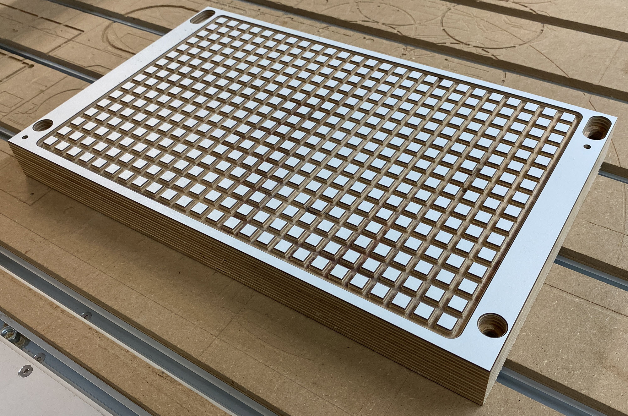
400 x fräsen + 400 x 1mm Phase um die Blöcke (incl. 5mm Werkzeug-Abheben pro Block im Schnellgang) ohne einen einzigen Schrittverlust. (ohne Absaugung)
Nach fast einem Jahr des Rätselns und Ärgers bin ich schon mal extrem froh, das Problem eindeutig aufgespürt zu haben.
Den anderen Stepper habe ich ebenfalls wieder zurück getauscht. Der ursprünglich verbaute ist sehr viel leiser und hochwertiger.
Bzgl. eines Lösungsansatzes habe ich heute mal einen Minimalansatz getestet und schlich ein Erdungskabel (erstmal als Wurfleitung) an die Spindel angeschlossen und auf Masse verbunden.
Die ersten Tests mit MDF und der Absaugmaske waren schon mal vielversprechend.
Keinerlei statische Aufladung bemerkbar, keine Schrittverluste.
Wenn damit das Problem gelöst wäre, hätte dies schon Charm.
Ansonsten habe ich noch immer die Option mit leitfähigem Filament im Hinterkopf.
Mal schauen wie sich das weiter entwickelt.
Vielen Dank nochmal an alle Helfer!
Gruß Jens
+++++++++++++++++++++++++++++++++++++++++
Today I finished my vacuum plate.
400 x milling + 400 x 1mm phase around the blocks (incl. 5mm tool lift-off per block in fast mode) without a single step loss. (without suction)
After nearly one year of puzzling and annoyance I am already extremely glad to have tracked down the problem clearly.
I also exchanged the other stepper back. The originally installed is much quieter and higher quality.
Regarding a solution, I tested a minimal approach today and connected a ground cable (first as a throw line) to the spindle and connected to ground.
The first tests with MDF and the suction mask were already promising.
No static charge noticeable, no step losses.
If this solved the problem, it would be charming.
Otherwise, I still have the option with conductive filament in mind.
Let's see how this develops further.
Thanks again to all the helpers!
Greetings Jens
20 Aug 2023 21:09
scaling problem on CNC Router was created by geertd
scaling problem on CNC Router
Category: Advanced Configuration
Hi,
A while ago, I installed LinuxCNC on a CNC Router and have been using it since then without major problems.
Configuration:
- LinuxCNC 2.7.15, using GMoccapy as GUI
- 3-axis CNC Router, with rack and pinion stepper motors on X and Y and a ballscrew positioner on Z. Max. X 1500mm, Max Y 2500mm
Until now, I mostly did small projects which generally are not critical regarding dimensions, and some bigger projects, but never experienced any problems regarding dimensions. I guess I was lucky that also the bigger projects were not very critical.
However, recently I realised that I have a scaling problem: My Y axis seems to be scaling 0.5 % bigger than necessary. If I cut a square that is 1000mm by 1000mm, the final dimension of the square in X is spot on, but the dimension in Y is 1005 mm. Cutting other size dimensions confirm that the scaling in Y is consistently 0.5% bigger than it should be.
The X and Y axis have identical stepper motors, identical rack and pinions and transmissions. They also have identical stepper drivers. So having the same scaling (steps per mm) in the configuration should give the same results for X and Y, but as mentioned above this is not the case.
First I thought of the stepper motor loosing steps, but in that case, I would expect the dimensions in Y to be shorter, not longer and also not as consistent as they seem to be. Also, I discovered this error while cutting 3mm thick hardboard with a 6mm endmill on a 1,5kW spindle, so cutting forces are probably not the issue.
I could of course adapt the Y axis scaling until right, but having the same mechanical configurations for both axis, something tells me this should not be OK and the scaling for X and Y should be the same....
Is there any other parameter in LinuxCNC configuration or parameter files that could affect axis scaling that I am not aware of?
Geert
19 Aug 2023 05:15 - 19 Aug 2023 05:29
Replied by Jensner on topic Stepper-Encoder an einem Stepper via Parallelport nachrüsten
Stepper-Encoder an einem Stepper via Parallelport nachrüsten
Category: Deutsch
Das Problem ist in meinem Falle kein elektrisches Bauteil im Absaugstrang, sondern vielmehr die extrem hohe, elektrostatische Aufladung des Absaugschlauchs und des aus PLA selbst gedruckten Absaugkopfes, welcher auf die Spindel aufgesteckt wird.
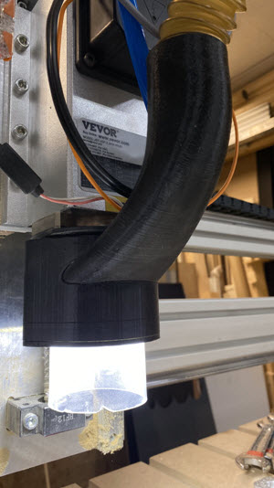
Durch die Verwirbelungen und relativ hohen Geschwindigkeiten lädt sich schon der Kopf an der Spindel elektrostatisch auf. Des weiteren war es wohl nicht sehr schlau von mit den Absaugschlauch durch ein HT-Rohr zu verlegen. Dies verstärkt aus meiner Sicht die elektrostatische Aufladung nochmals.
Das heißt, ich muss mir leider eine andere Absauglösung einfallen lassen. Sehr schade, denn dieser Kopf hat sehr gut funktioniert, aber wenn damit das Z-drifting behoben wird, ist es das auf jeden Fall wert.
Alternativ wäre auch die Frage ob das Problem mit einem eigenen Erdungskabel für den Absaugkopf in der Schleppkette gelöst wäre oder dadurch noch verschlimmert würde.
Vielen Dank
+++++++++++++++++++++++
In my case, the problem is not an electrical component in the suction line, but rather the extremely high electrostatic charge of the suction hose and the suction head, which is printed from PLA and attached to the spindle.
Due to the turbulence and relatively high speeds, even the head on the spindle becomes electrostatically charged. Furthermore, it was probably not very clever of me to lay the suction hose through a HT pipe. In my opinion, this increases the electrostatic charge even more.
This means that I unfortunately have to come up with another suction solution. Very unfortunate, because this r head worked very well, but if it fixes the Z-drifting, it's definitely worth it.
Alternatively, the question would also be whether the problem would be solved with a dedicated ground cable for the suction head in the drag chain, or would that make it worse.
Thanks a lot
Time to create page: 1.821 seconds