Hurco KMB-IS CNC update
- _big_
- Offline
- Premium Member
-

Less
More
- Posts: 87
- Thank you received: 13
04 Aug 2020 03:21 - 04 Aug 2020 04:12 #177165
by _big_
Replied by _big_ on topic Hurco KMB-IS CNC update
Last edit: 04 Aug 2020 04:12 by _big_.
Please Log in or Create an account to join the conversation.
- _big_
- Offline
- Premium Member
-

Less
More
- Posts: 87
- Thank you received: 13
04 Aug 2020 03:26 #177167
by _big_
Replied by _big_ on topic Hurco KMB-IS CNC update
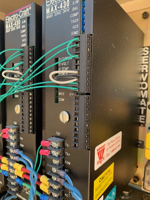
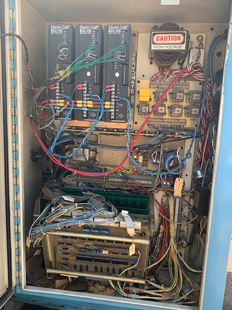
Right hand cabinet in all its glory:
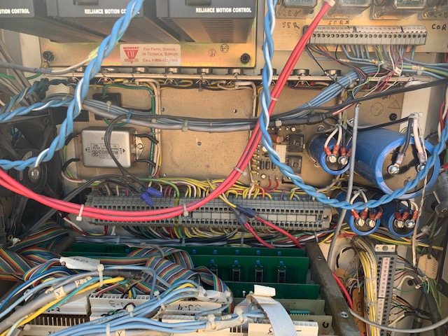
Close up of power supply in RH cabinet. Pretty simple in appearance. Only 4 easily swapped out electrolytics. There is a row of 12 TO3 packaged semiconductor devices. Probably linear voltage regulators. A bit surprised there are so many. But should be easy to repair if necessary.
Close up of power supply in RH cabinet. Pretty simple in appearance. Only 4 easily swapped out electrolytics. There is a row of 12 TO3 packaged semiconductor devices. Probably linear voltage regulators. A bit surprised there are so many. But should be easy to repair if necessary.
Please Log in or Create an account to join the conversation.
- _big_
- Offline
- Premium Member
-

Less
More
- Posts: 87
- Thank you received: 13
04 Aug 2020 03:27 #177168
by _big_
Replied by _big_ on topic Hurco KMB-IS CNC update
Please Log in or Create an account to join the conversation.
- _big_
- Offline
- Premium Member
-

Less
More
- Posts: 87
- Thank you received: 13
04 Aug 2020 03:31 #177169
by _big_
Replied by _big_ on topic Hurco KMB-IS CNC update
Attachments:
Please Log in or Create an account to join the conversation.
- _big_
- Offline
- Premium Member
-

Less
More
- Posts: 87
- Thank you received: 13
04 Aug 2020 04:09 #177170
by _big_
Replied by _big_ on topic Hurco KMB-IS CNC update
I did find the air input hose. It comes out of the top of the machine... kinda weird. I wonder if machine is supposed to sit with its back up against a wall? Although the oiler seems to be mounted to the rear.
I looked more closely at the Hurco computer. There appear to be 1979 and 1980 date codes on the parts. I was doing computer system design during the era (paid for the Porsche). I can look at the parts and tell you what most of them do. I have no interest in trying to resurrect it. A $50 Raspberry PI is about the size of a credit card, runs LinuxCNC, a modern GUI and accepts G-Code from CAD programs over the network.
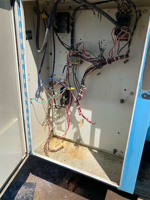
Don't see the missing contents of the left hand cabinet as a big problem. VFDs are relatively cheap. Quill motor should be pretty easy once the servo system is working.
Try to verify that the non-quill motor part of the machine runs on single phase 220V. Which of course is readily available. Bring up the power supplies. Try to figure out how to cleanly separate the Hurco computer from the rest of the machine. And then attach the PI probably via some Mesa board.
The beast is currently parked outside. Needs to be moved to a warm and dry place where restoration can begin. I don't think I need to mention how difficult it is to move a 3500 pound milling machine .
.
I looked more closely at the Hurco computer. There appear to be 1979 and 1980 date codes on the parts. I was doing computer system design during the era (paid for the Porsche). I can look at the parts and tell you what most of them do. I have no interest in trying to resurrect it. A $50 Raspberry PI is about the size of a credit card, runs LinuxCNC, a modern GUI and accepts G-Code from CAD programs over the network.
Don't see the missing contents of the left hand cabinet as a big problem. VFDs are relatively cheap. Quill motor should be pretty easy once the servo system is working.
Try to verify that the non-quill motor part of the machine runs on single phase 220V. Which of course is readily available. Bring up the power supplies. Try to figure out how to cleanly separate the Hurco computer from the rest of the machine. And then attach the PI probably via some Mesa board.
The beast is currently parked outside. Needs to be moved to a warm and dry place where restoration can begin. I don't think I need to mention how difficult it is to move a 3500 pound milling machine
Please Log in or Create an account to join the conversation.
- CORBETT
-

- Offline
- Elite Member
-

Less
More
- Posts: 286
- Thank you received: 113
04 Aug 2020 16:32 #177256
by CORBETT
Replied by CORBETT on topic Hurco KMB-IS CNC update
At work, super busy, but some quick responses and I will be more detailed later.
Your cabinet is really close to mine. Yours is definitely a later model machine as the yellow Hurco tag is the dead give away for that.
The spindle motor can be re-wired very easily to use the LV 220 side. There should be 9 leads (I think 9, may be 8) that are in the motor. You change up the leads and that will make it either the 220 or 440. 440/480 was the norm for just about all factories. Not many step above 480 to the machinery. Once again, 440/480 would cut the electric bill in half compared to using 220V.
Looks like VFD was ripped out for some reason.
Yes the single phase out of the transformer will supply all 3 of the amps at one time. This is where you can follow the wiring back to the left side cabinet and get power to the transformer.
Not sure of the air piece on the side... definitely looks like a air solenoid and my guess is that is a "cool mist/air system" that would have had a line going over to the spindle area for blowing refrigerated air onto the parts during machining. It looks to be in the same place that most of the coolant lines bolted, so that is best guess.
No need to take anything apart at the limit switches (Proximity Switches). All of the wiring comes back to the TB-8 connector and then over to the limit switch board and then over to the amps and back down to the computer card cage. I will take pics and show you where to tie in as there is no need to take anything apart anywhere else on the machine for the proximity switches. I took all of it apart to trace it, only to have to put it all back together with nothing done to any of it. You did find them as they are identical to mine.
Most all of the work you will do is in the one right hand cabinet. If you do what I did, you should be able to get the machine fired up pretty quick. Very little work to do everywhere else as most all the wiring from all equipment terminates in the right hand cabinet.
Hope this helps until I can respond tonight.
Robert
Please Log in or Create an account to join the conversation.
- CORBETT
-

- Offline
- Elite Member
-

Less
More
- Posts: 286
- Thank you received: 113
04 Aug 2020 16:42 - 04 Aug 2020 16:44 #177257
by CORBETT
Replied by CORBETT on topic Hurco KMB-IS CNC update
I forgot to add.
There are 2 ways to move the machine. I am not sure what you have as we have several forklifts up to 30K lbs. So i never have a moving problem. If you need to move it with say a pallet jack. You can go get 4pcs of 5/8" threaded eyelets and thread them into the 4 holes in the base of the machine where you would bolt it to the floor. The holes are for bolting the machine down, but they are tapped also so that you can do this. When you screw in the eyelets, they should have a large enough hole to slide 1" pipe through. You can put a jack on each side and slowly jack the machine up, we used 2 floor jacks and would bring the front up about a inch, then move to the back and keep moving back and forth front to back, while adding wood chocks along and along to get the machine up and off the ground enough to slide the pallet jack under. Me and my father did this for one machine to get it out of a guy's carport. We showed up with our little 5K hyster lift and it would not clear the carport door. SO had to improvise LOL.
Always be safe on moving. That is how riggers loose a finger. Met plenty of riggers missing a index or middle finger LOL
Robert
Last edit: 04 Aug 2020 16:44 by CORBETT. Reason: clarify
Please Log in or Create an account to join the conversation.
- _big_
- Offline
- Premium Member
-

Less
More
- Posts: 87
- Thank you received: 13
04 Aug 2020 19:51 #177273
by _big_
Replied by _big_ on topic Hurco KMB-IS CNC update
We've already moved the beast once. It needs to be moved to the "restoration shop", which happens to be my garage. This garage is across town and down a somewhat steep driveway from the machine's current location. We have to load a forklift on one trailer. Load the beast on a flatbed trailer. Get these trailers across town. Back the flatbed down the driveway and hope everything fits. And of course when you're moving something so heavy, it needs to be done with care. If things go well, it will take the better of a day to move the machine.
I've been thinking more about how to breath life back into the Hurco. First, I need to find out the voltage used to power the drive transformer, and the DC supply transformer in the RH cabinet. Its probably 220VAC, but need to know more than probably.
I was thinking about not even trying to power up the Hurco computer. One of the reasons is the "backplane" the boards plug into is really poorly done. There's a ribbon cable bus and then some loose wired hard attached power wires I think. Why they didn't build a motherboard to plug the daughter cards into is beyond me. Maybe I should plug the thing back together as well as I can and apply the juice. It might actually do something sensical. If it does, then that's the best starting point for figuring out the go-zintas and go-zoutas. Probably the worst thing that could happen is I could somehow damage the servo drives. But I think that's a pretty remote possibility.
Please Log in or Create an account to join the conversation.
- CORBETT
-

- Offline
- Elite Member
-

Less
More
- Posts: 286
- Thank you received: 113
04 Aug 2020 20:37 #177278
by CORBETT
Replied by CORBETT on topic Hurco KMB-IS CNC update
True, there should not be any way to mess up the servo amp unless wiring for the power was messed up somewhere. Especially if you detach the analog inputs to avoid anything else coming in. Be aware that most likely one or all 3 of the axis will start to try and move when you power the amps. If you do not have the limit switches (proximity switches) working, then you can crash an axis. So be careful to just power up the servo amp with out first having a way of killing power really quick. If it were me WITH POWER OFF TO MACHINE, I would reach down into the machine and turn the Y ball screw until the table was in the very middle, X is not reachable unless you take off the cover to the servo motor and turn at the motor coupling (may have to do this elsewhere, been awhile), but do the same and put the table in the middle. Do the same for Z, but keep in mind you have very little run out in Z, only 6" travel in Z, 3" each way. That way if you fire up the amps and they start moving the motors you will not crash. They usually move with a slow drift, but you do not know what the previous person did to the machine, so you have to be careful that one of the axis doesn't just suddenly take off, hence why you need a way to kill power to amps really quick.
One thing is that if you keep the wiring as is and do not bypass the contactor you will need to power other items to get the servo amps to work. Back when I was speaking of safety blocks in a previous post, they are in this part also. The K5 relays are what control the ACC contactor that powers the amps, but I know you sent a pic with just a little different setup. Yours does not appear to have the ACC contactor in the same place. I will go back later tonight and try and take a look and see how it was done (this is a bad work week for me, so not much time). If you were going to fire up the amps, the air pressure switch needs air pressure at the back and the emergency stop chain will need to be working also. They would have had some type of contactor to break power to the amps for an emergency condition. But since you may have an upgrade from MIdwest, this could be wired totally different. They are not going to bypass safety themselves either as they are a company that would be facing liability and lawsuits f that was the case.
But once you get power to the transformer and it passes to the amps, whether through a relay or contactor, then you should be ready to see what the servos are going to do. You can do a quick and dirty movement of the X using a AAA battery (NOT 9V BATTERY) but this is dangerous and you would need to understand several things before attempting this. But this is the way to check if everything is fine with the servos and can move the table around to check.
Moving down hills are not fun at all, definitely tie off well as better overkill than underkill and have the machine on its side. Yeah for what you described, I would plan all day and very slow methodical way of doing it. We are riggers also as we install fire pumps and have to be careful with trying to keep the assembly from flexing to avoid re-aligning the driver to the pump Measure everything before going with machine to make sure height isn't a problem, but head can come off for more room getting in. We took the entire spindle assembly off to move one of them.
Will be back later,
Robert
Please Log in or Create an account to join the conversation.
- Teknic_Servo
-

- Offline
- New Member
-

Less
More
- Posts: 15
- Thank you received: 7
04 Aug 2020 20:50 #177281
by Teknic_Servo
Replied by Teknic_Servo on topic Hurco KMB-IS CNC update
Hi _big_,
I'm an engineer with Teknic and I recently came across this post; I thought it might be helpful to quickly clarify a few questions/comments about the ClearPath motors.
tommylight is correct - LinuxCNC is compatible with the ClearPath SD motors (www.teknic.com/products/clearpath-brushl...stepper-replacement/) as long as you provide 5-24VDC Step and Direction signals. If you’re planning on reusing your existing servo drives though, then ClearPath is not an appropriate option. ClearPath is an integrated servo motor, servo drive, and encoder; so to use it on your machine you would need to replace your existing motors and drives.
Speaking to the output power of ClearPath, there are options ranging from 100 W, NEMA 23 and 34 motors to higher-powered, NEMA 56 and 143 models, which output up to 5.8 kW. The optimal ClearPath motors depend on your application's peak and continuous torque requirements, target speed(s), and a number of other factors.
Without more information about your application, I can't say whether or not Teknic motors could be a good fit, but I'd be happy to discuss it further if you are interested.
If you have any questions about sizing or using ClearPath, please feel free to give us a call at 585-784-7454, or use our "Contact Us" form online. (www.teknic.com/contact/).
Best,
Nick S. - Teknic Servo Systems Engineer
Please Log in or Create an account to join the conversation.
Moderators: piasdom
Time to create page: 0.157 seconds

