Hurco KMB-IS CNC update
- _big_
- Offline
- Premium Member
-

Less
More
- Posts: 87
- Thank you received: 13
11 Aug 2020 00:35 #177851
by _big_
Replied by _big_ on topic Hurco KMB-IS CNC update
Hi Robert,
Ya the parts manual sounds like it could be very useful.
And the diagram showing the TB numbers is also useful.
It is interesting that the servo xformer is so small. Makes me think my brown mystery transformer is a 220-> 110 unit. And the servo transformer is completely MIA?
Thanks again!
Leith
Ya the parts manual sounds like it could be very useful.
And the diagram showing the TB numbers is also useful.
It is interesting that the servo xformer is so small. Makes me think my brown mystery transformer is a 220-> 110 unit. And the servo transformer is completely MIA?
Thanks again!
Leith
Please Log in or Create an account to join the conversation.
- CORBETT
-

- Offline
- Elite Member
-

Less
More
- Posts: 286
- Thank you received: 113
11 Aug 2020 02:32 #177856
by CORBETT
Leith,
Yes, its hard to say what is going on. As I was driving up the interstate, it hit me that someone could have moved the transformer off the power supply. So I would still follow out the red power wires feeding the amps. Especially since it looks so much like the one from the power supply.
There is other somewhat good news. I had a few other manuals that I did not remember. I have a 83 manual for the same machine as yours. It's the Owners Manual, but still have a few pages that are worth having. it shows your style of machine exactly.
I just got back from work about a hour ago. I have to go back up there in the morning as I couldn't totally fix the problem, so I can't stay up very late tonight. Plus this is another super busy week for me. I will start trying to break it down and post some here, but I will PM you about emailing the full PDF. There is a lot of pages that will not be useful as it is all about using the OEM controller, but can look through just for knowledge about it. Also, yeah definitely will get the parts manual.
Will keep you posted.
Robert
Replied by CORBETT on topic Hurco KMB-IS CNC update
Leith,
Yes, its hard to say what is going on. As I was driving up the interstate, it hit me that someone could have moved the transformer off the power supply. So I would still follow out the red power wires feeding the amps. Especially since it looks so much like the one from the power supply.
There is other somewhat good news. I had a few other manuals that I did not remember. I have a 83 manual for the same machine as yours. It's the Owners Manual, but still have a few pages that are worth having. it shows your style of machine exactly.
I just got back from work about a hour ago. I have to go back up there in the morning as I couldn't totally fix the problem, so I can't stay up very late tonight. Plus this is another super busy week for me. I will start trying to break it down and post some here, but I will PM you about emailing the full PDF. There is a lot of pages that will not be useful as it is all about using the OEM controller, but can look through just for knowledge about it. Also, yeah definitely will get the parts manual.
Will keep you posted.
Robert
Please Log in or Create an account to join the conversation.
- CORBETT
-

- Offline
- Elite Member
-

Less
More
- Posts: 286
- Thank you received: 113
15 Aug 2020 17:11 #178303
by CORBETT
Leith,
I have been tied up all week. I am trying to quote 2 jobs this weekend as both bid Monday, one was sent to me Wednesday morning so I am swamped at the moment. I have not had time to do anything else, but wanted to send a quick message of why I have not been back on here for a few days.
One other thing from the past, when you go to demo the pendant. You can save the jog wheel to re-use. It has almost the same type of encoder as each axis. Also, there are a couple of pots and buttons that may be usable. I only kept the Mpeg wheel and jog pots, but did keep all the demo-ed parts just for future tinker projects.
When I get past this burst of work, I will get back to sending more info.
Robert
Replied by CORBETT on topic Hurco KMB-IS CNC update
Leith,
I have been tied up all week. I am trying to quote 2 jobs this weekend as both bid Monday, one was sent to me Wednesday morning so I am swamped at the moment. I have not had time to do anything else, but wanted to send a quick message of why I have not been back on here for a few days.
One other thing from the past, when you go to demo the pendant. You can save the jog wheel to re-use. It has almost the same type of encoder as each axis. Also, there are a couple of pots and buttons that may be usable. I only kept the Mpeg wheel and jog pots, but did keep all the demo-ed parts just for future tinker projects.
When I get past this burst of work, I will get back to sending more info.
Robert
Please Log in or Create an account to join the conversation.
- _big_
- Offline
- Premium Member
-

Less
More
- Posts: 87
- Thank you received: 13
16 Aug 2020 02:57 #178346
by _big_
Replied by _big_ on topic Hurco KMB-IS CNC update
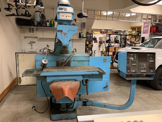
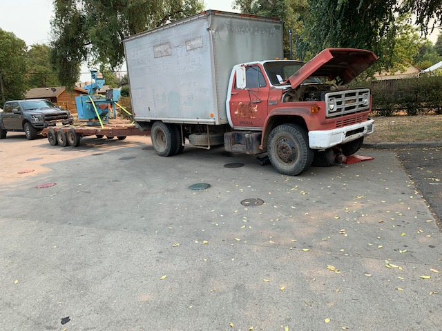
The Hurco has landed! Warm and dry now.
But not without some starter issues with the truck.
Some mysteries were solved today.
The brown transformer thingy on the back is a Sola ferroresonant power conditioner. Single phase. Apparently, they had noisy power in the shop this was in and they used it to keep the electronics happy.
And, in the LH cabinet there is definitely a spot where the servo drive AC was connected to a transformer. The transformer is gone.
And probably another spot for a 240-120 transformer that is also missing.
Attachments:
Please Log in or Create an account to join the conversation.
- CORBETT
-

- Offline
- Elite Member
-

Less
More
- Posts: 286
- Thank you received: 113
17 Aug 2020 19:46 - 17 Aug 2020 19:50 #178522
by CORBETT
Leith,
Yes, now you can do some work without worry of mother nature. Plus right there at you instead of travelling to work on it. That bottom pic reminds me of our many adventures in equipment moving. I will have to find and post a pic or two, LOL. My grandfather had a GMC flat bed like that, want to say it was a 66 model....
Yes, looks like Tom (Tommylight) was correct after all with the line filter reply. Ok good, sounds like you are starting to get the transformers figured out. Bad part is why did they take them out? .... hopefully nothing else wrong and they simply were taking parts out for some other project.
I still have a lot to do this week also, but will get back to sending you some info soon. If you start on some particular item and need that schematic or parts breakdown, let me know and I will try to get it taken care of for you to keep you going.
Will be back soon,
Robert
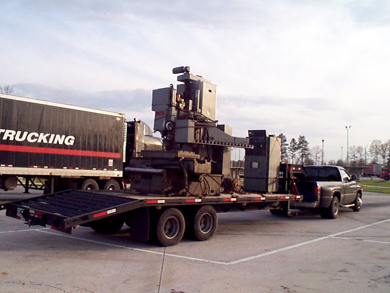
Hey here is a pic I found where I moved our middle size mill back about 15-20 years ago (man it doesn't feel like that far back). It's a Monarch VMC 75, and weighed a little over16,000lbs for the mill itself. The GE 1050 Controller at the front of the trailer weighed just over 1,000lbs, and the Hyperdex 360 4th axis was about 700lbs.
EDIT: I forgot to add that my "Pucker" factor went to "11"
.
Replied by CORBETT on topic Hurco KMB-IS CNC update
Leith,
Yes, now you can do some work without worry of mother nature. Plus right there at you instead of travelling to work on it. That bottom pic reminds me of our many adventures in equipment moving. I will have to find and post a pic or two, LOL. My grandfather had a GMC flat bed like that, want to say it was a 66 model....
Yes, looks like Tom (Tommylight) was correct after all with the line filter reply. Ok good, sounds like you are starting to get the transformers figured out. Bad part is why did they take them out? .... hopefully nothing else wrong and they simply were taking parts out for some other project.
I still have a lot to do this week also, but will get back to sending you some info soon. If you start on some particular item and need that schematic or parts breakdown, let me know and I will try to get it taken care of for you to keep you going.
Will be back soon,
Robert
Hey here is a pic I found where I moved our middle size mill back about 15-20 years ago (man it doesn't feel like that far back). It's a Monarch VMC 75, and weighed a little over16,000lbs for the mill itself. The GE 1050 Controller at the front of the trailer weighed just over 1,000lbs, and the Hyperdex 360 4th axis was about 700lbs.
EDIT: I forgot to add that my "Pucker" factor went to "11"
.
Attachments:
Last edit: 17 Aug 2020 19:50 by CORBETT.
Please Log in or Create an account to join the conversation.
- _big_
- Offline
- Premium Member
-

Less
More
- Posts: 87
- Thank you received: 13
18 Aug 2020 02:08 #178561
by _big_
Replied by _big_ on topic Hurco KMB-IS CNC update
OK! Been able to spend a little quality time with the Hurco now that its landed in my shop.
As mentioned in the past the AC power system is basically a disaster zone. In the LH (AC power) cabinet you can see clearly where someone removed the ~80 VAC servo drive transformer. The servo drive AC supply wires end at a big empty space just about right for a 3 KVA transformer. There's another spot that looks to be the 240VAC to 120VAC transformer.
This is not a huge problem... just a problem. In the short term I'm going to connect the DC supply directly to the 120VAC line. And I've acquired a 20 amp variac to generate the servo drive 80 VAC. 20 amps is probably not enough to run all three servos full tilt, but initially I think it will work just fine. In the mean time were looking for a 3KVA 80VAC transformer.
The compressed air system is in a state similar to the AC supplies. The primary dryer/regulator/oil_injector is missing. There are several loose air pipes lying about. A bit of a puzzle to figure out what to do.
I have acquired a new dryer/regulator/oil_injector. Its now a challenge to figure out how to hook things up. Here's my guess.
Machine definitely didn't have a flood coolant system. But there's a spot on the arm from which something was removed and an airline running to about that spot.
I think there was a spray lubricator there.
I found the air pressure lockout switch. Hurco manual says it drops out less than 80 PSI. My shop air may not be that high. May have to work on that.
The oiler system is also somewhat hacked up. At least one loose line. And the line from the oiler to the machine is missing. I think I need some of this tubing: www.freelin-wade.com/nylon-plastic-tubing/dot221#1 And the fittings to go with it. Working on that.
Removed the belt from the Z servo. Will probably remove the belt from the Y servo. And Robert was correct, the X servo is connected to the screw with a coupler and not a belt. Thinking about attempting to decouple the X motor from the screw. I really like the idea of powering this thing up with the servo completely disconnected. That way I can test the limit switches and E-Stop and make sure they are working without fear of crashing something.
I'm getting a good handle on the pieces I need to get this thing back together. Now I need to work on acquisition of those pieces.
One I get the air connected, I'll probably try to power up the electronics as it is. It will be interesting to see if the Hurco computer runs at all.
As mentioned in the past the AC power system is basically a disaster zone. In the LH (AC power) cabinet you can see clearly where someone removed the ~80 VAC servo drive transformer. The servo drive AC supply wires end at a big empty space just about right for a 3 KVA transformer. There's another spot that looks to be the 240VAC to 120VAC transformer.
This is not a huge problem... just a problem. In the short term I'm going to connect the DC supply directly to the 120VAC line. And I've acquired a 20 amp variac to generate the servo drive 80 VAC. 20 amps is probably not enough to run all three servos full tilt, but initially I think it will work just fine. In the mean time were looking for a 3KVA 80VAC transformer.
The compressed air system is in a state similar to the AC supplies. The primary dryer/regulator/oil_injector is missing. There are several loose air pipes lying about. A bit of a puzzle to figure out what to do.
I have acquired a new dryer/regulator/oil_injector. Its now a challenge to figure out how to hook things up. Here's my guess.
shop air ----+----> dryer ----+----> regulator ---+---> oil injector -----> regulator ---+--> spindle valve
             |                                    |                                      |
             |                                    |                                      +--> oiler valve
         lockout switch                      spray mist
Machine definitely didn't have a flood coolant system. But there's a spot on the arm from which something was removed and an airline running to about that spot.
I think there was a spray lubricator there.
I found the air pressure lockout switch. Hurco manual says it drops out less than 80 PSI. My shop air may not be that high. May have to work on that.
The oiler system is also somewhat hacked up. At least one loose line. And the line from the oiler to the machine is missing. I think I need some of this tubing: www.freelin-wade.com/nylon-plastic-tubing/dot221#1 And the fittings to go with it. Working on that.
Removed the belt from the Z servo. Will probably remove the belt from the Y servo. And Robert was correct, the X servo is connected to the screw with a coupler and not a belt. Thinking about attempting to decouple the X motor from the screw. I really like the idea of powering this thing up with the servo completely disconnected. That way I can test the limit switches and E-Stop and make sure they are working without fear of crashing something.
I'm getting a good handle on the pieces I need to get this thing back together. Now I need to work on acquisition of those pieces.
One I get the air connected, I'll probably try to power up the electronics as it is. It will be interesting to see if the Hurco computer runs at all.
Attachments:
Please Log in or Create an account to join the conversation.
- CORBETT
-

- Offline
- Elite Member
-

Less
More
- Posts: 286
- Thank you received: 113
19 Aug 2020 04:21 #178670
by CORBETT
Leith,
Looks like you are making progress...
Here is the electrical side of the emergency stop string with the air switch. This was for my type of machine, but yours should be pretty much the same. I will see if I can find the air circuit. This might not work with your other setup that you just got, but will give the idea what Hurco did with the wiring.
I am still doing some long hours each day and will be back with more eventually.
Robert
Replied by CORBETT on topic Hurco KMB-IS CNC update
Leith,
Looks like you are making progress...
Here is the electrical side of the emergency stop string with the air switch. This was for my type of machine, but yours should be pretty much the same. I will see if I can find the air circuit. This might not work with your other setup that you just got, but will give the idea what Hurco did with the wiring.
I am still doing some long hours each day and will be back with more eventually.
Robert
Attachments:
Please Log in or Create an account to join the conversation.
- _big_
- Offline
- Premium Member
-

Less
More
- Posts: 87
- Thank you received: 13
19 Aug 2020 14:38 - 19 Aug 2020 14:52 #178710
by _big_
Replied by _big_ on topic Hurco KMB-IS CNC update
Thanks again Robert. That's some pretty timely information.
I have just about resurrected the compressed air system. Acquiring parts for the oiler system.
I guess "COR" is the symbol they use for contactor?
Without detailed knowledge of the E-stop and compressed air interlock, I had assumed I needed to have the compressed air system working before applying power.
Since I'm planning on connecting directly to the servo drive AC input power and the DC supplies AC input, these interlocks won't be working at initial power up. Although I am intending to restore those functions eventually.
Since there will be no E-Stop, I need to be extra careful about crashing an axis.
Nonetheless, this is very useful information. The next question is, where do the limit switches connect in?
Leith
Last edit: 19 Aug 2020 14:52 by _big_.
Please Log in or Create an account to join the conversation.
- _big_
- Offline
- Premium Member
-

Less
More
- Posts: 87
- Thank you received: 13
19 Aug 2020 14:50 #178713
by _big_
Replied by _big_ on topic Hurco KMB-IS CNC update
And as long as I have your attention.
We're trying to decipher this Kwik Switch 200 thing. We have a Kwik Switch 200 end mill holder inbound.
But we have no idea how it actually locks into the quill. And we don't have the Kwik Switch 200 wrench.
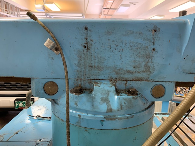
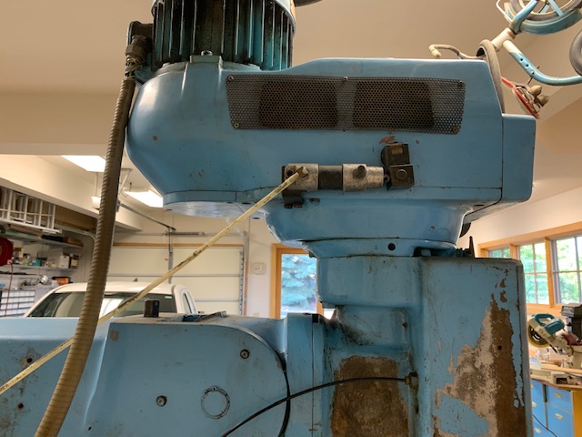
But I'm wondering about this air cylinder on the quill drive. Does this have something to do with Kwik Switch 200, or maybe some quill brake thing??
Attachments:
Please Log in or Create an account to join the conversation.
- CORBETT
-

- Offline
- Elite Member
-

Less
More
- Posts: 286
- Thank you received: 113
19 Aug 2020 17:51 - 19 Aug 2020 17:53 #178733
by CORBETT
Leith,
Ok just got back in town... still have work to do, but have a little easier day.
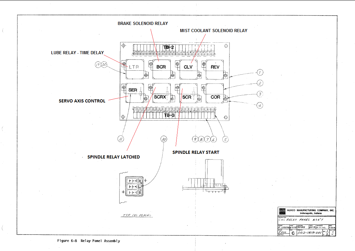
The COR relay is one of the K5 type relays where the block of 8 relays on the board is mounted. I will pull and attach where I have the K5 relays listed as what they are. I don't have the REV or COR relay listed on the sketch, but what the COR does is pretty much supply the main power connection to the controls when you push the power switch on the pendant. In other words, when the COR relay energizes it will send power to several other sections and "latch" power to the circuit where you push the power pushbutton When you see the emergency stop schematic, the left side of the string shows the "Pendant Power Pushbutton" just above the TB3 connection #1 and #2. So when you operate the pushbutton, it energizes the circuit and the COR relay enacts and keeps the circuit latched. As long as you have power to the main cabinet power supply, then the circuit should be powered and should work when you push the power button on the upper left side of the pendant. You will also need air pressure on the pressure switch as that is part of the circuit, but all of the wiring should be wired up just simply need to plug off the air down stream of the pressure switch so you can put air to it temporarily. Plus the emergency stop should still be wired up. If for some reason it is not, then I will check to see which 2 terminals to connect to on the TB3 connector to make the emergency stop switch loop.
Also, yes the air solenoid on the side of the head could be what supplies the air brake. I do not know how it looks on your machine as it is pretty large on mine. I doubt it will be that big in yours. Will find pics of mine, but I believe you have seen it before on the web when looking at other retrofits. You should be able to grab and spin the spindle. If you cannot, then the brake is on or something locked up. Mine only enacts when I have the air pressure up and the control on. If it just has air only, the spindle brake is off and you can still spin the spindle. With this said, when you get everything working and trying to get the brake working, you can test by trying to spin. You should hear the brake come on when it enacts anyway.
The Kwik Switch tool just simply goes right up into the spindle and the nut will spin and lock in place. The nut is spring loaded and will flip around on its own. If it does not work smoothly or correctly, then some maintenance will have to be done as the toolholder could potentially fall out. I will try to shoot a video of mine and you can see it in operation. Super fast tool changes, you will love it.
Here is the schematic showing the K5 relays
I know I didn't answer everything, but I will be back and try to answer more in a bit.
Hope this helps,
Robert
Replied by CORBETT on topic Hurco KMB-IS CNC update
Leith,
Ok just got back in town... still have work to do, but have a little easier day.
The COR relay is one of the K5 type relays where the block of 8 relays on the board is mounted. I will pull and attach where I have the K5 relays listed as what they are. I don't have the REV or COR relay listed on the sketch, but what the COR does is pretty much supply the main power connection to the controls when you push the power switch on the pendant. In other words, when the COR relay energizes it will send power to several other sections and "latch" power to the circuit where you push the power pushbutton When you see the emergency stop schematic, the left side of the string shows the "Pendant Power Pushbutton" just above the TB3 connection #1 and #2. So when you operate the pushbutton, it energizes the circuit and the COR relay enacts and keeps the circuit latched. As long as you have power to the main cabinet power supply, then the circuit should be powered and should work when you push the power button on the upper left side of the pendant. You will also need air pressure on the pressure switch as that is part of the circuit, but all of the wiring should be wired up just simply need to plug off the air down stream of the pressure switch so you can put air to it temporarily. Plus the emergency stop should still be wired up. If for some reason it is not, then I will check to see which 2 terminals to connect to on the TB3 connector to make the emergency stop switch loop.
Also, yes the air solenoid on the side of the head could be what supplies the air brake. I do not know how it looks on your machine as it is pretty large on mine. I doubt it will be that big in yours. Will find pics of mine, but I believe you have seen it before on the web when looking at other retrofits. You should be able to grab and spin the spindle. If you cannot, then the brake is on or something locked up. Mine only enacts when I have the air pressure up and the control on. If it just has air only, the spindle brake is off and you can still spin the spindle. With this said, when you get everything working and trying to get the brake working, you can test by trying to spin. You should hear the brake come on when it enacts anyway.
The Kwik Switch tool just simply goes right up into the spindle and the nut will spin and lock in place. The nut is spring loaded and will flip around on its own. If it does not work smoothly or correctly, then some maintenance will have to be done as the toolholder could potentially fall out. I will try to shoot a video of mine and you can see it in operation. Super fast tool changes, you will love it.
Here is the schematic showing the K5 relays
I know I didn't answer everything, but I will be back and try to answer more in a bit.
Hope this helps,
Robert
Attachments:
Last edit: 19 Aug 2020 17:53 by CORBETT.
The following user(s) said Thank You: _big_
Please Log in or Create an account to join the conversation.
Moderators: piasdom
Time to create page: 0.231 seconds

