Optimum Optimill MH50V CNC conversion

More
1 month 2 weeks ago #349723 by Unlogic
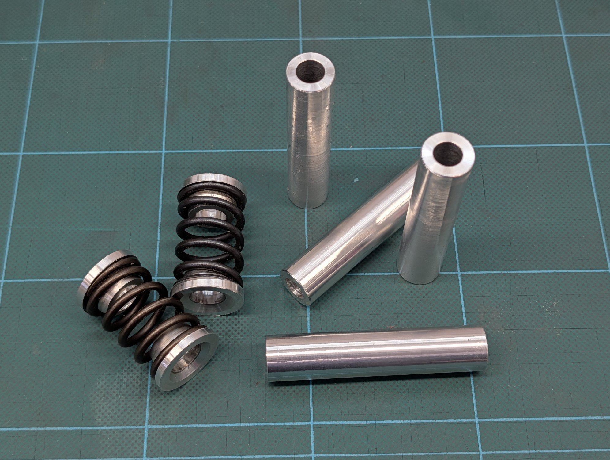
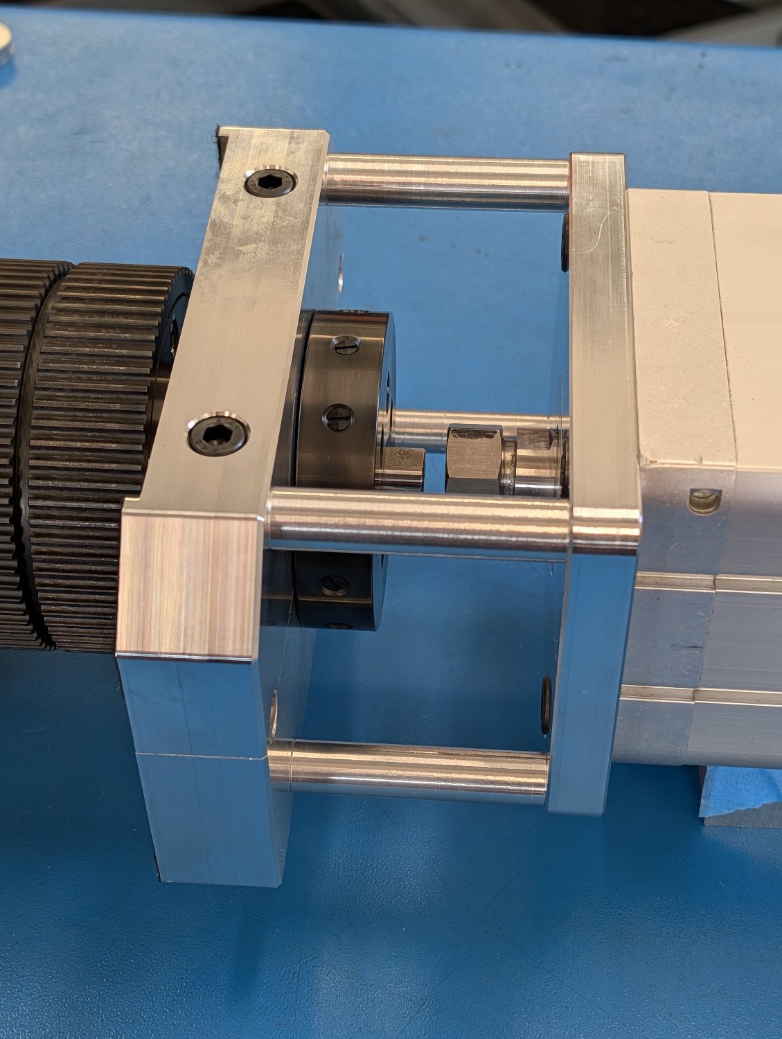
Here are the finished sleeves and the springs that hold down the pneumatic cylinder when it's idle. Used a set of old valve springs and retainers that were turned down a bit.


Please Log in or Create an account to join the conversation.
More
1 month 2 weeks ago #349724 by Unlogic
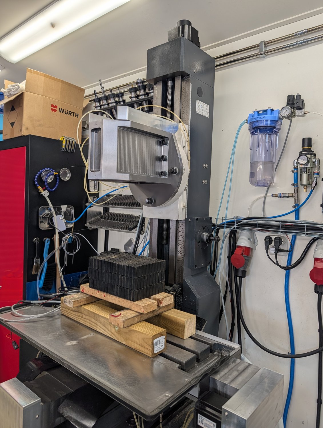
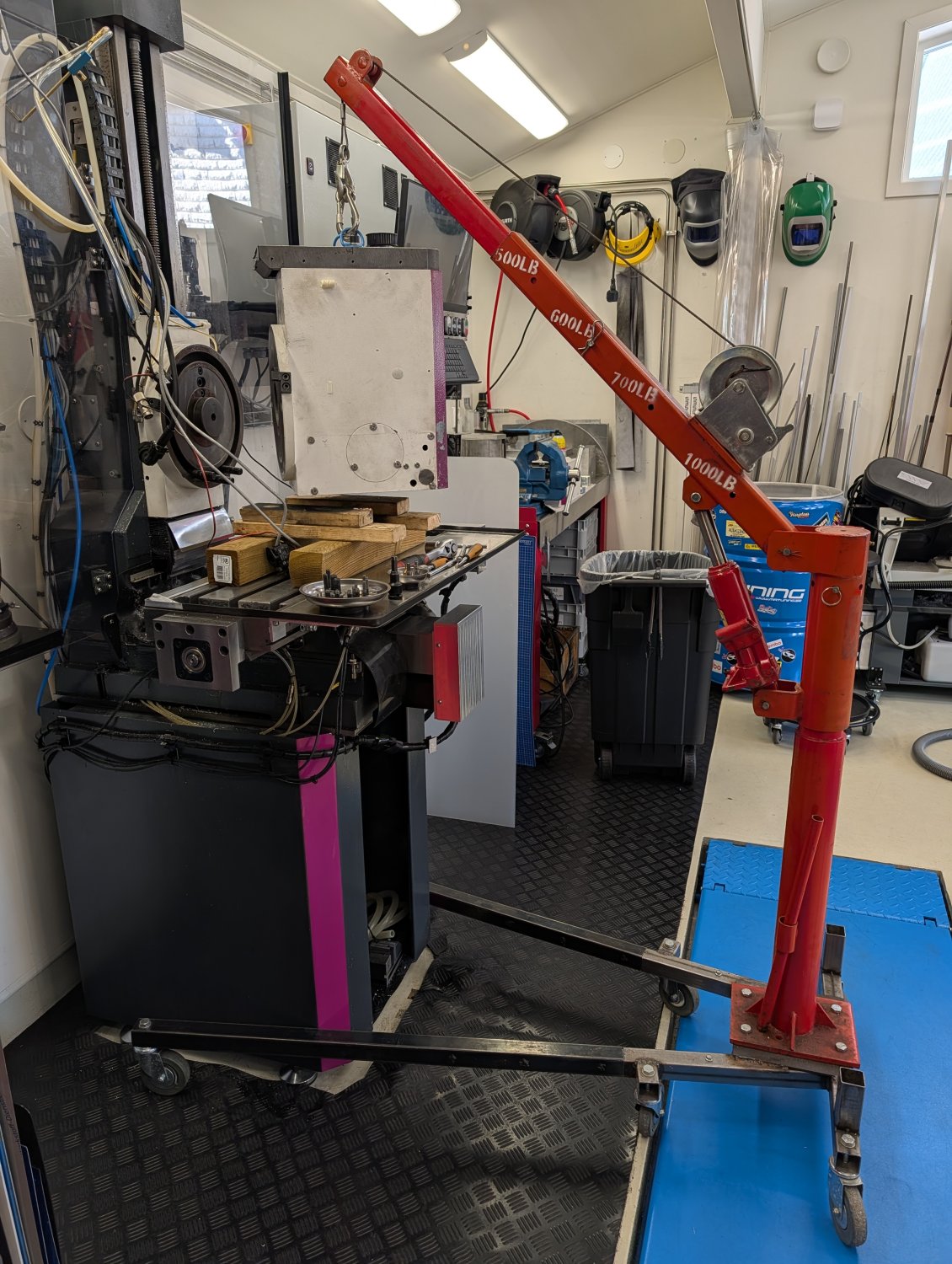
With all the new parts done I began taking the machine apart starting with the head.


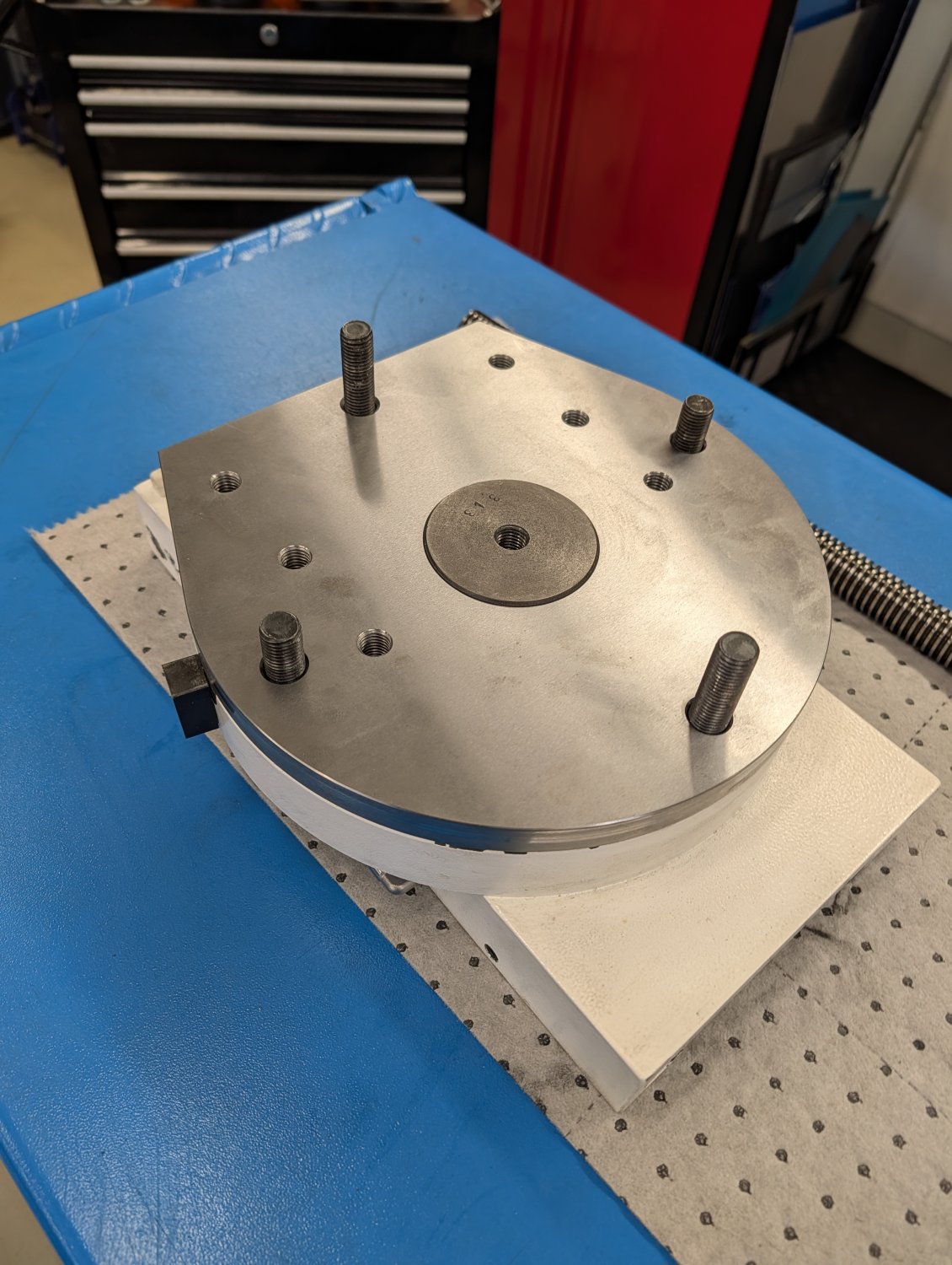
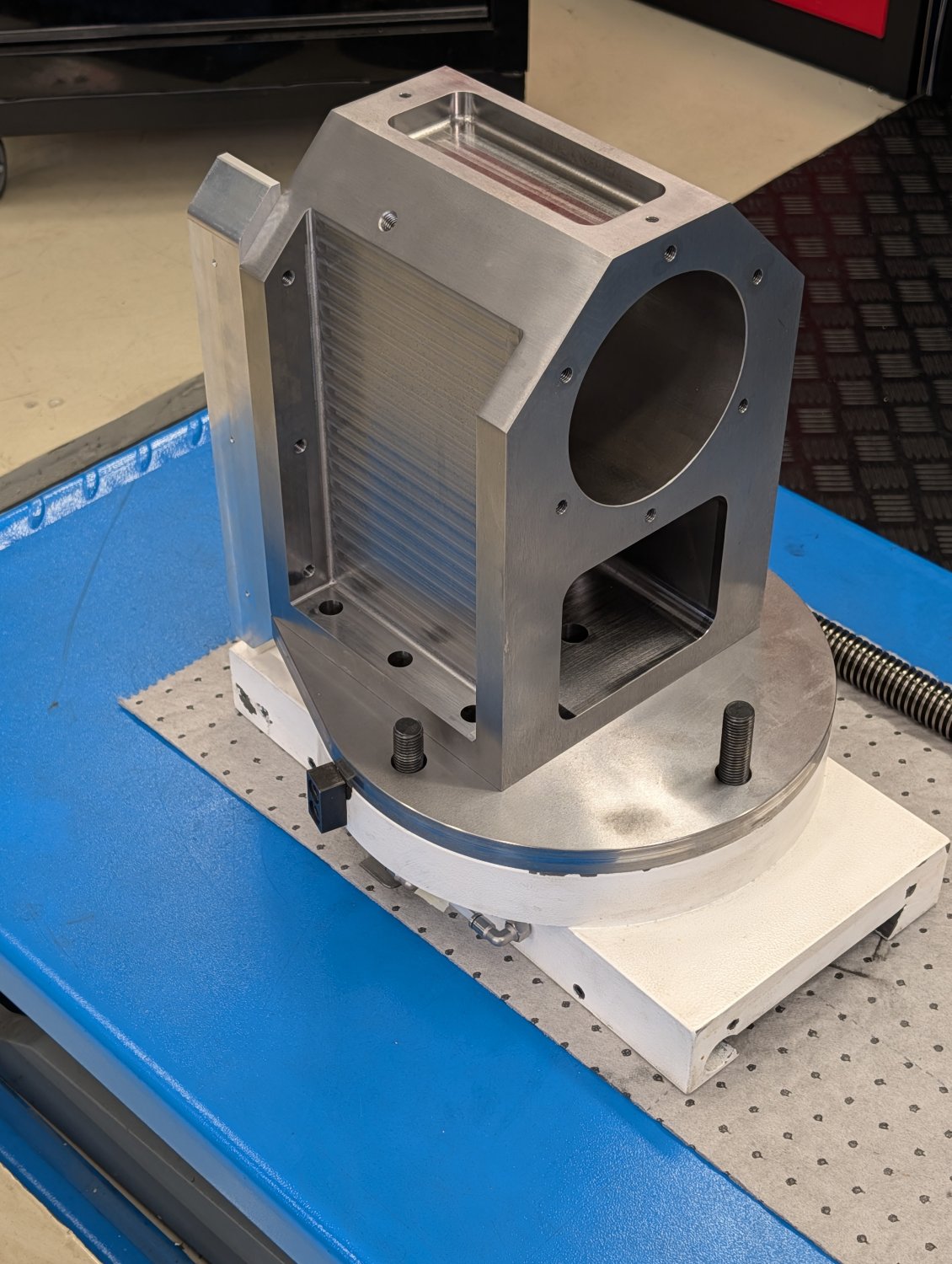
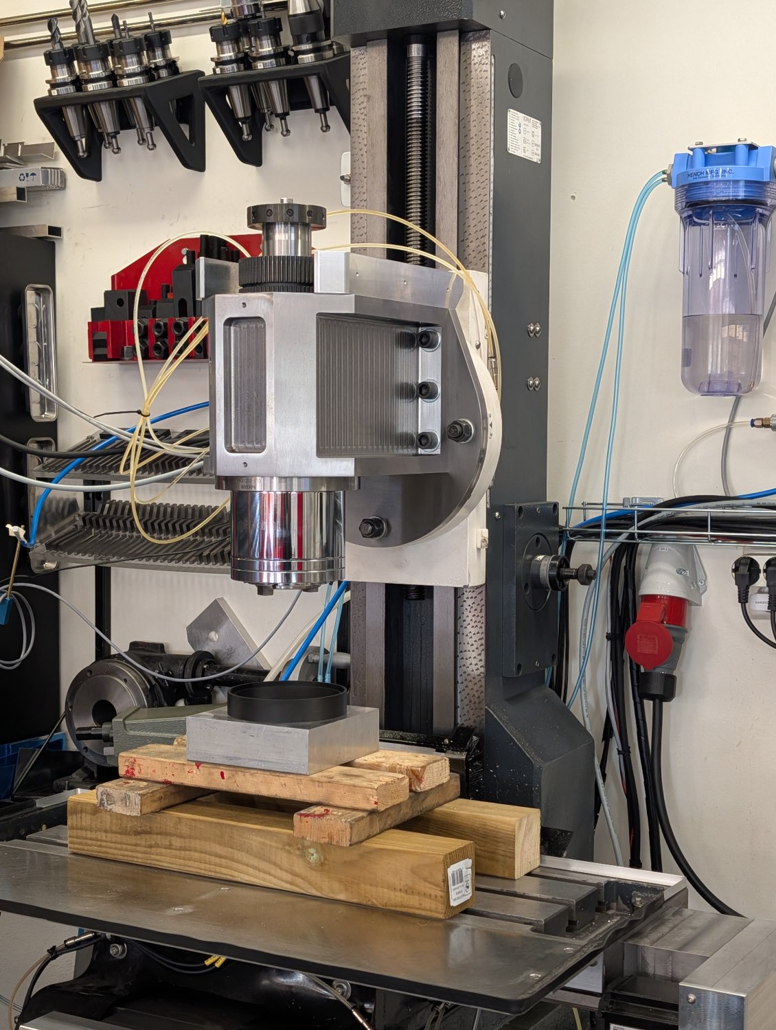
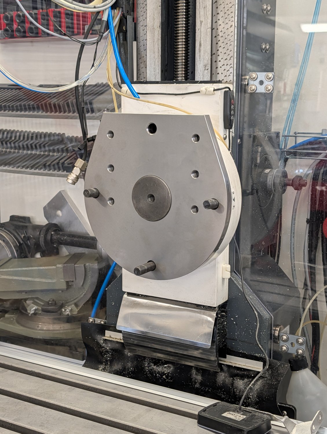
After that I did a test fit of the adapter plate for the new head which thankfully was a very tight fit.


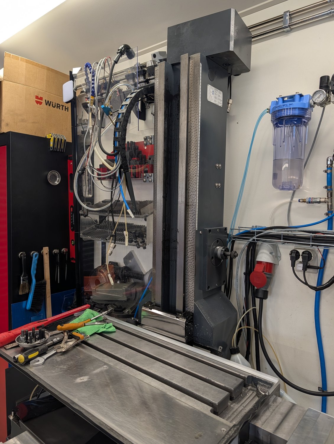
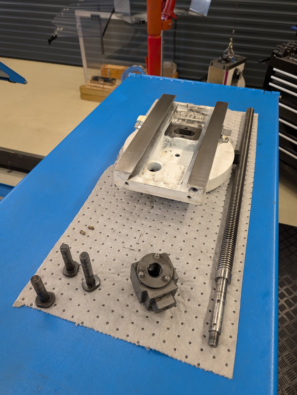
With the fitment confirmed I proceeded with removing the z-axis carriage from the machine.


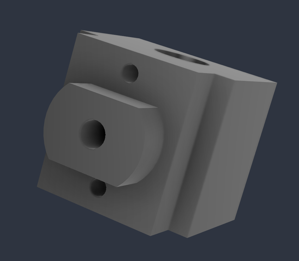
While I had everything apart I took the chance to make a CAD model of the mount for the z-axis ball nut so that I can make one for a ball screw later on.


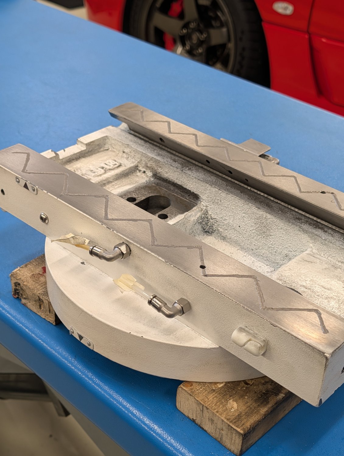
Next I proceeded with adding oil grooves to the z-axis carriage.


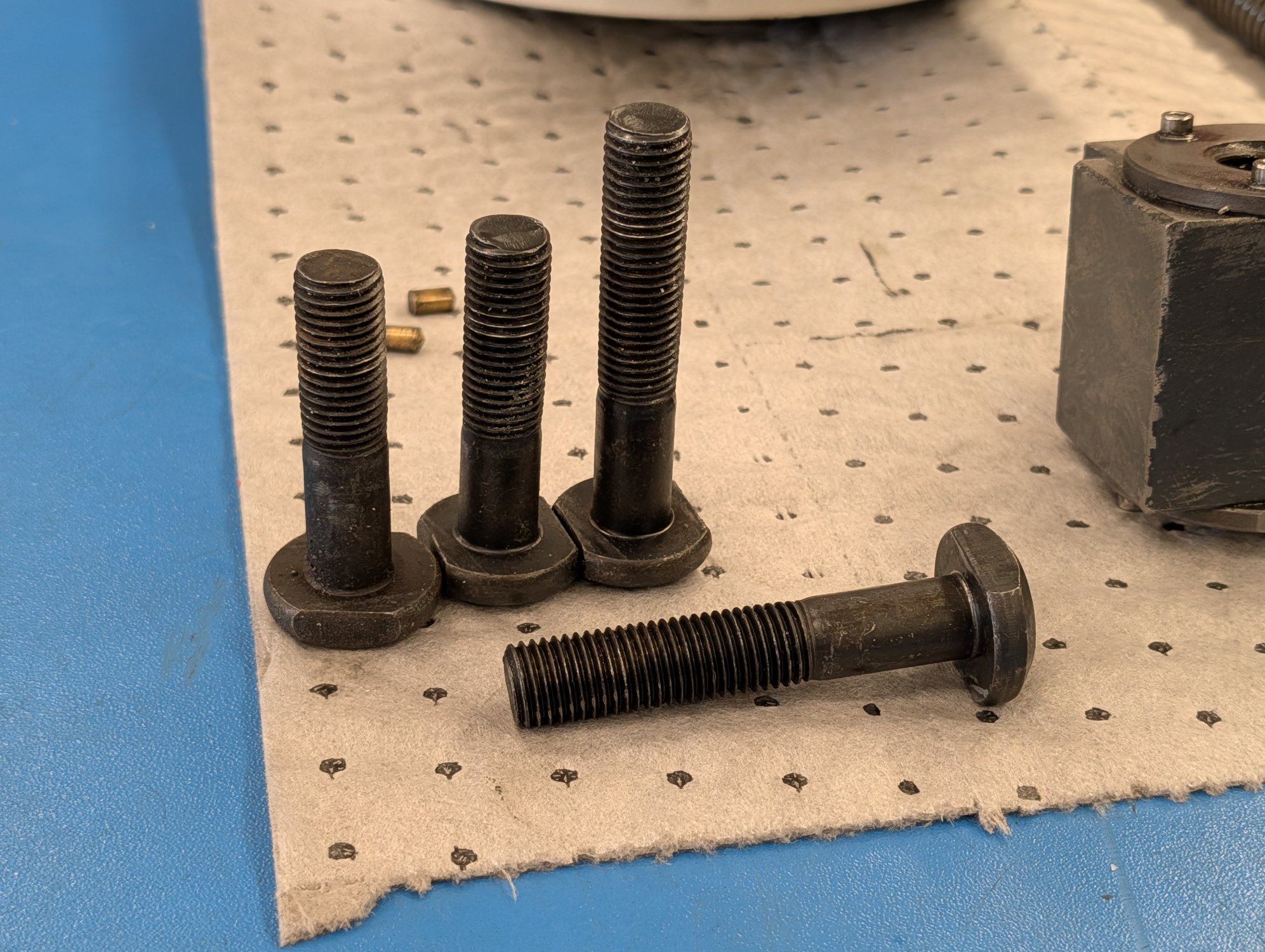
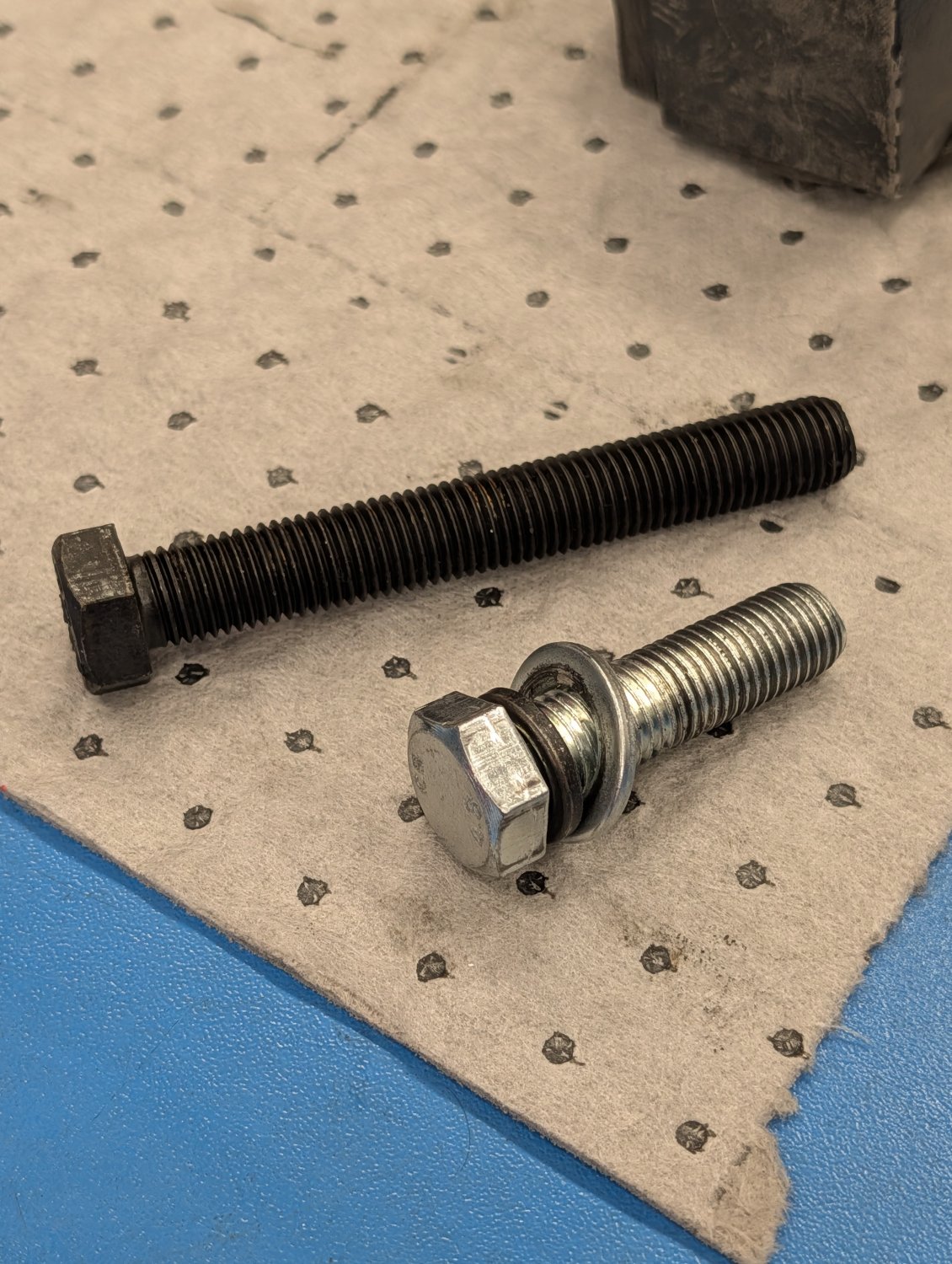
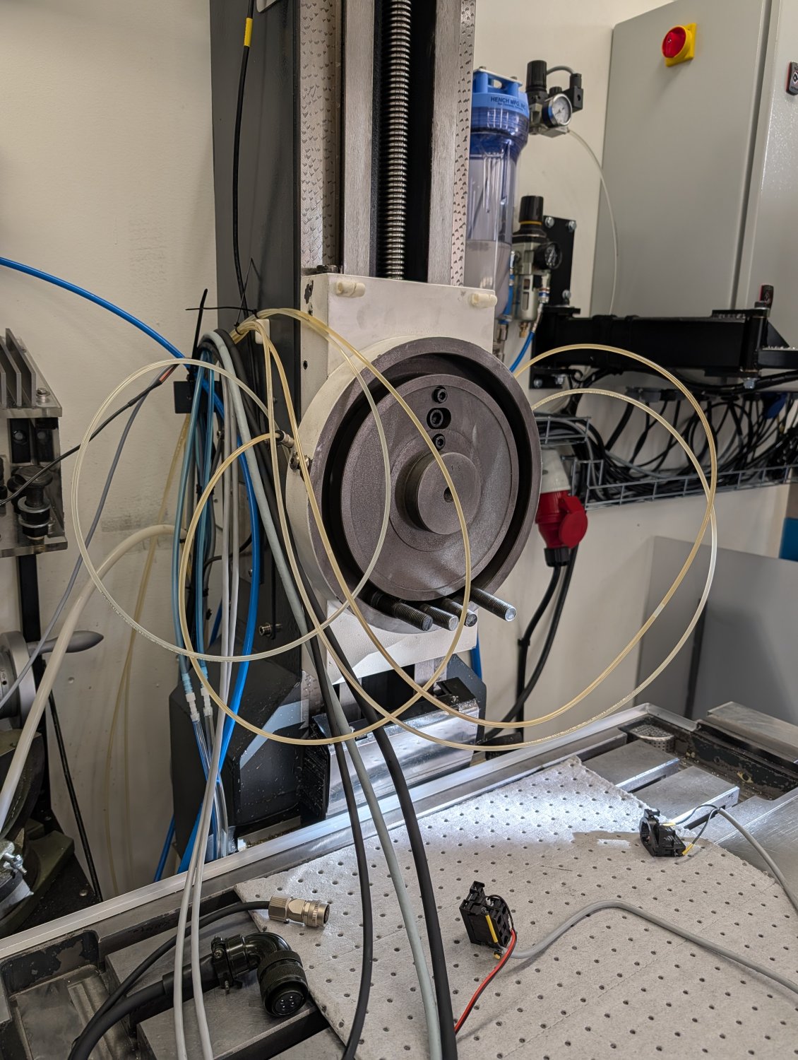
The stock head of this machine is attached using one center bolt and 3 outer bolts. The new head that I designed uses one more outer bolt for better rigidity. However the outer bolts have an oddly shaped head but luckily I manage to find a matching bolt.


Please Log in or Create an account to join the conversation.
More
1 month 2 weeks ago #349725 by Unlogic
 

With the bolts sorted I proceeded with quick test fitment of the major parts.


While I was doing this I noticed that the stock center bolt was only 4.8 grade which is very weak so I replaced it with a 12.9 grade bolt instead.


Before taking the machine apart I had taken the time to lookup which bearing type that is used for the z-axis lead screw on this machine as they have been making noises for quite some time.

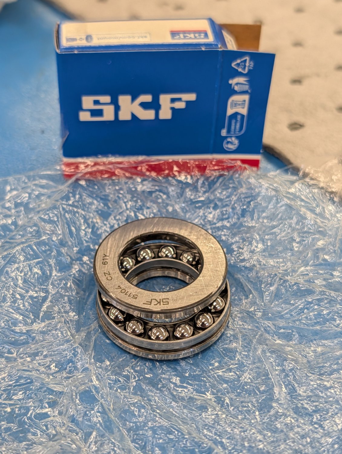
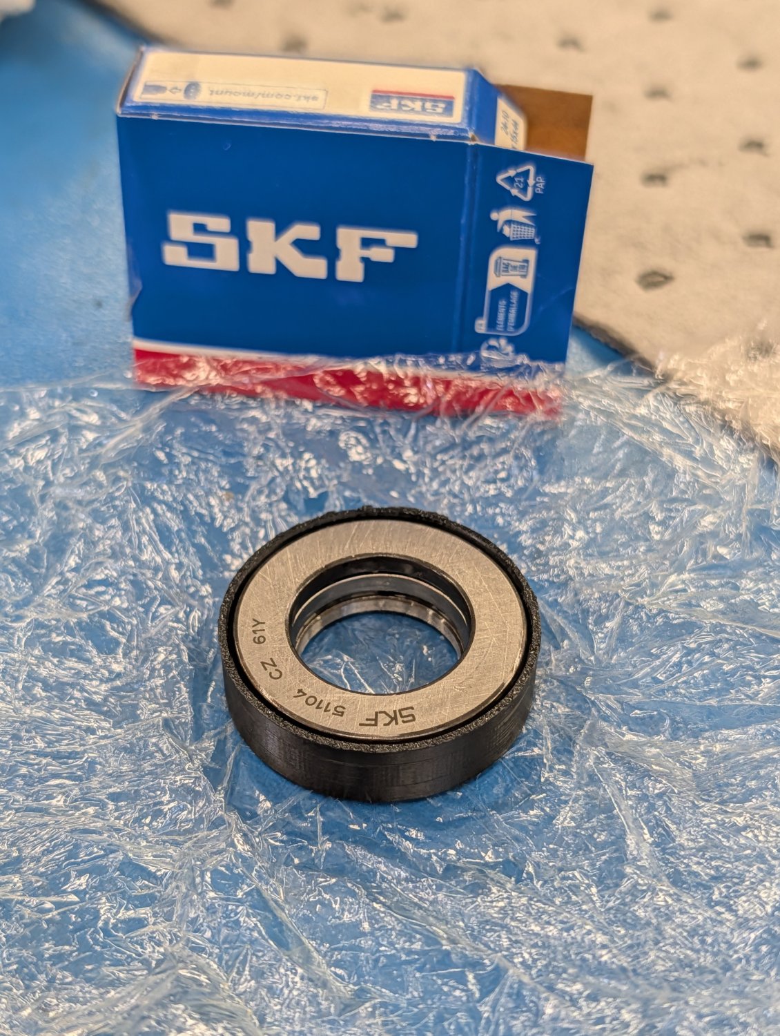
According to the manual for this machine the z-axis lead screw is supposed to use 51104 single direction thrust ball bearings so I ordered a set of those from SKF.

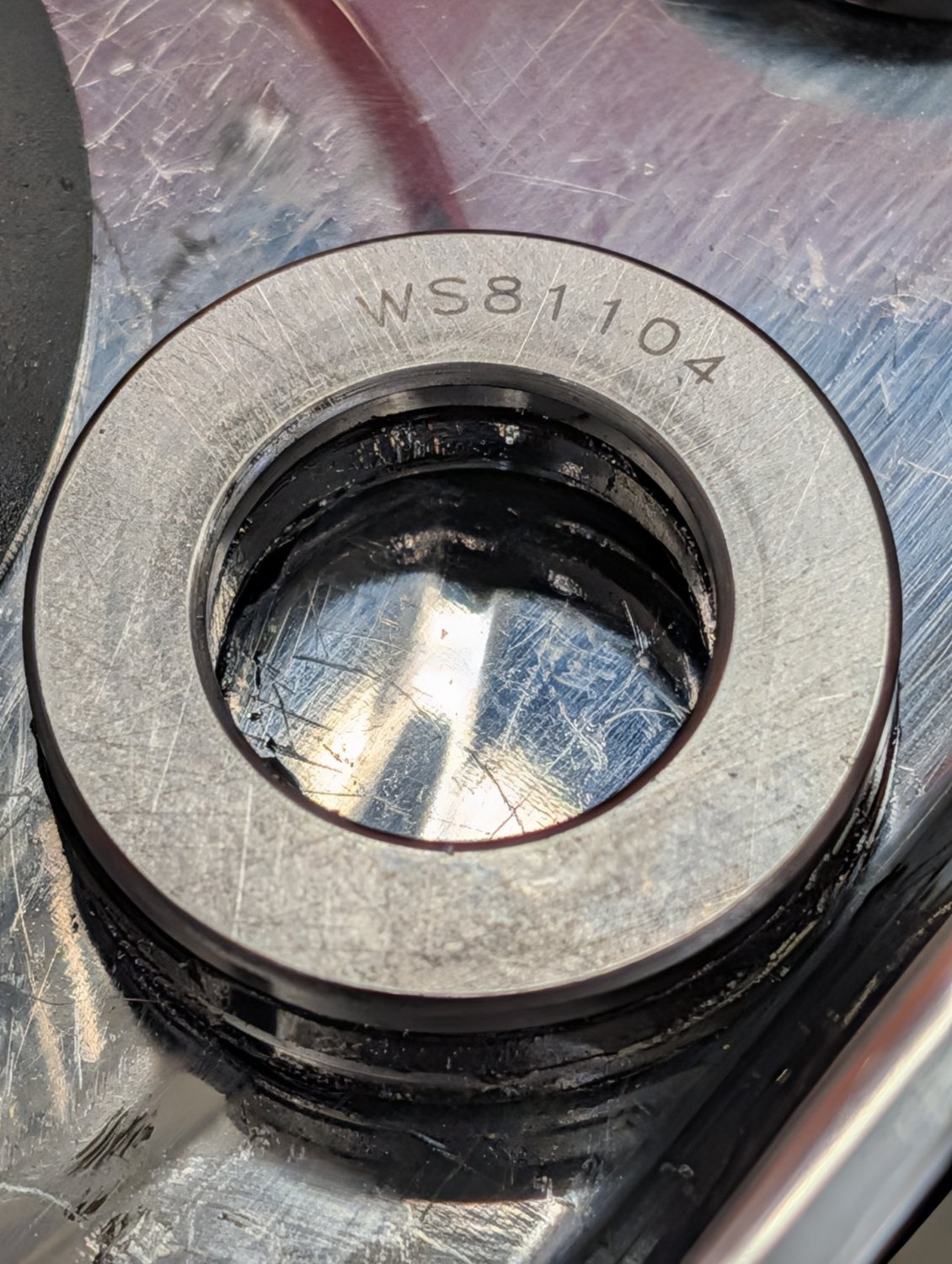
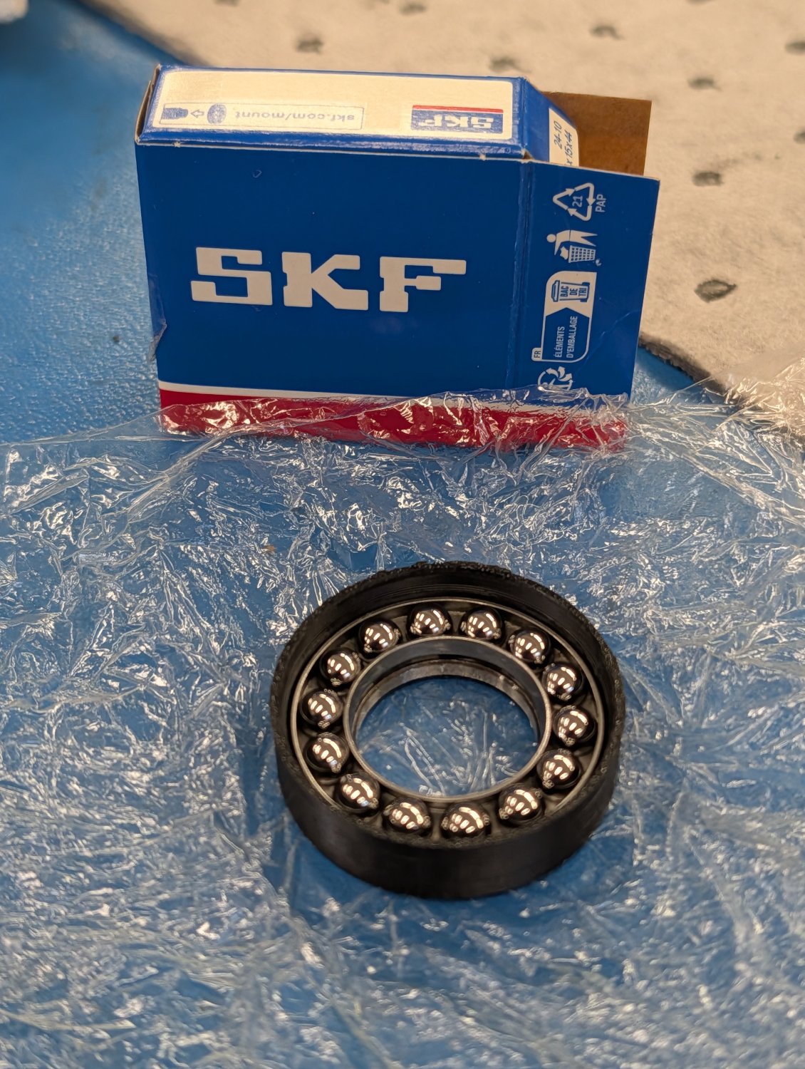
However when I removed the lead screw from the machine I was greeted by this, WS81104 roller bearings...


Roller bearings are much better at carrying this type of loads and I would have preferred to install a new set. But since all I had available was the 51104 single direction thrust ball bearings I installed them for now...

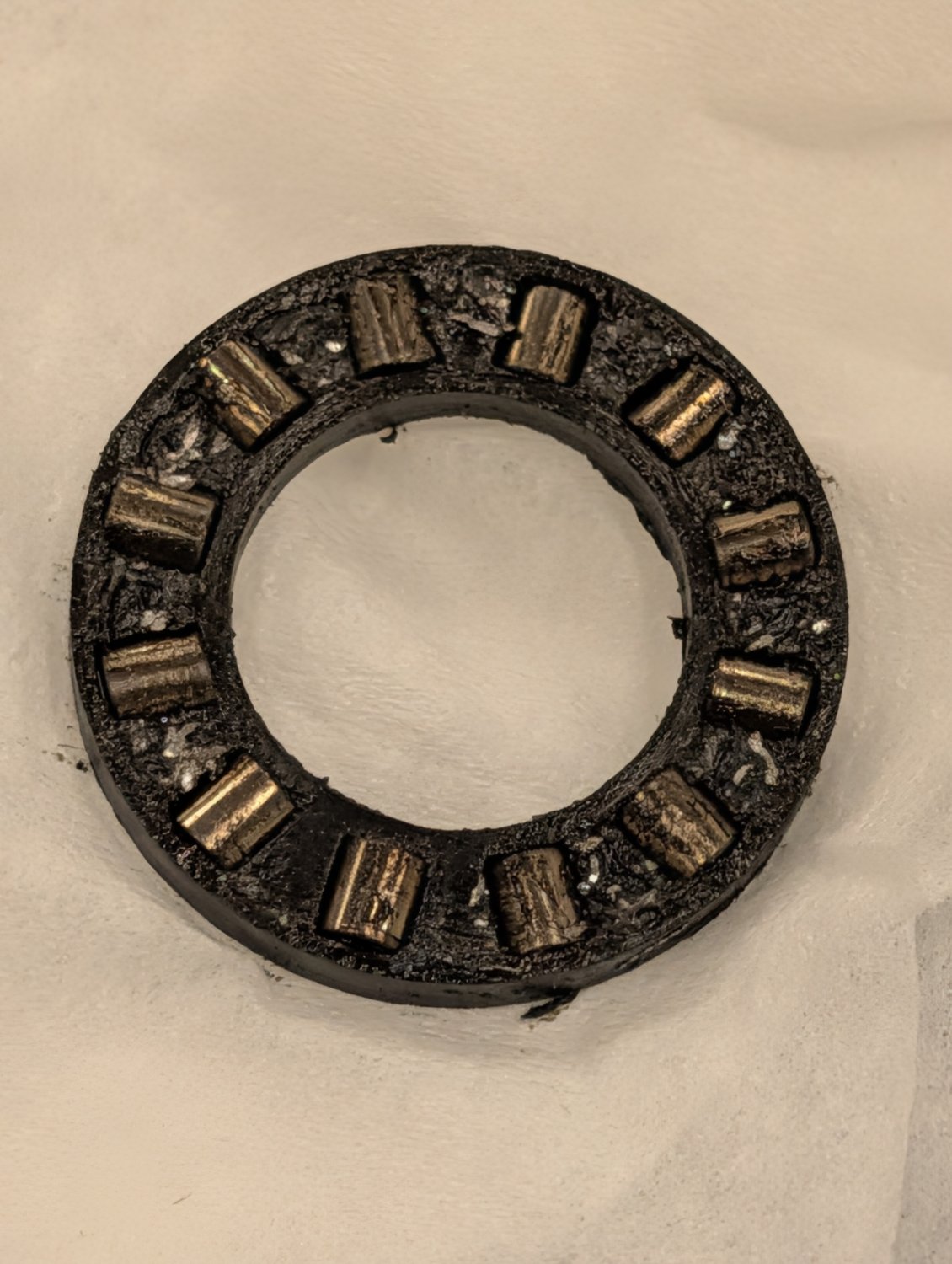
As you can see from the photo above the old roller bearings where full of metal chips which is not surprising given that they are of an open design.

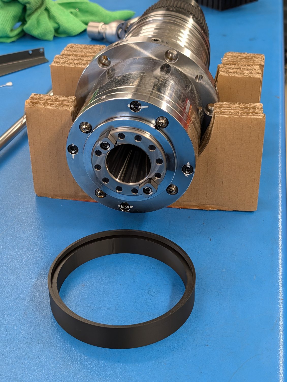
To try and avoid this issue with the new bearing I 3D printed a set of collars from ASA plastic for the new bearings.


The following user(s) said Thank You: besriworld

Please Log in or Create an account to join the conversation.
More
1 month 2 weeks ago #349726 by Unlogic
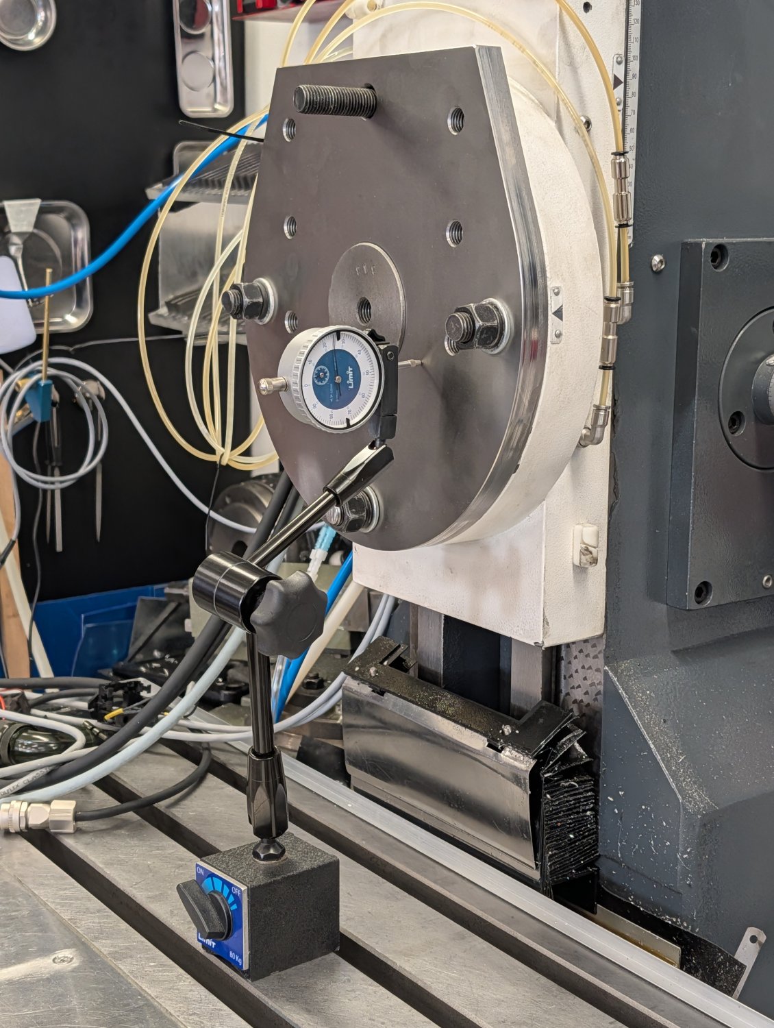
After getting the bearings sorted I reinstalled the z-axis carriage and the lead screw along with the lines for the central lubrication so that I could adjust the gibs and do some measurements.


This machine has always had a bit of a head nod which I've had to compensate for by shimming the head. I was hoping that it was a defect with the old head but it turned out to come from the z-axis carriage so I'll have to use shims for the new head too.


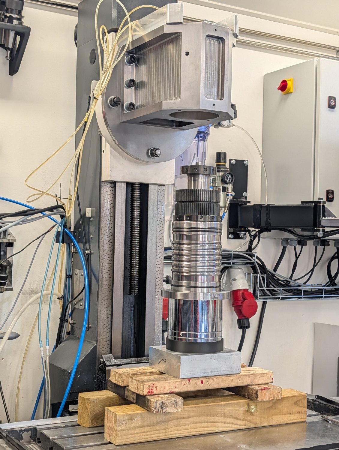
With the measurements taken I installed the new head.


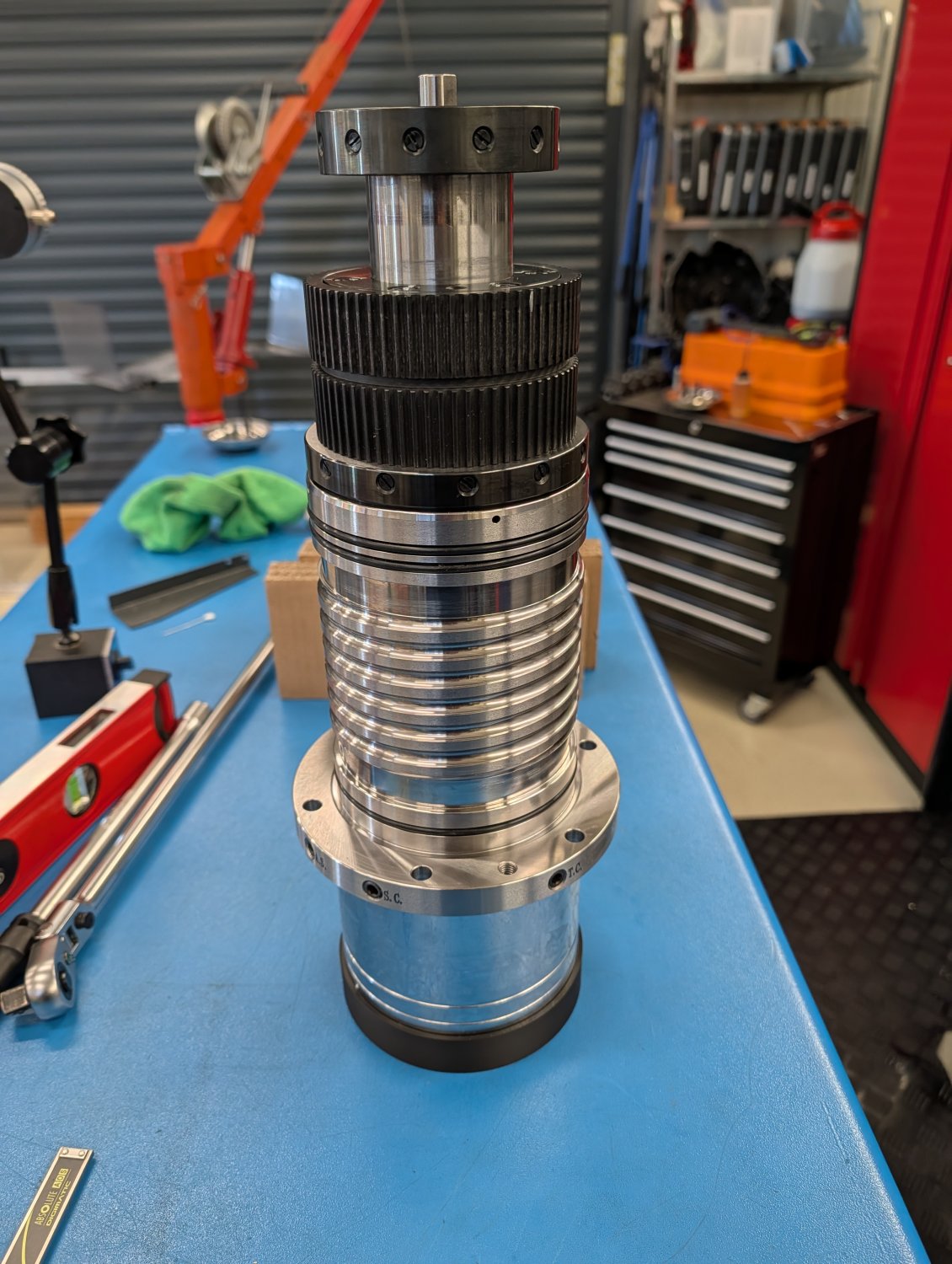
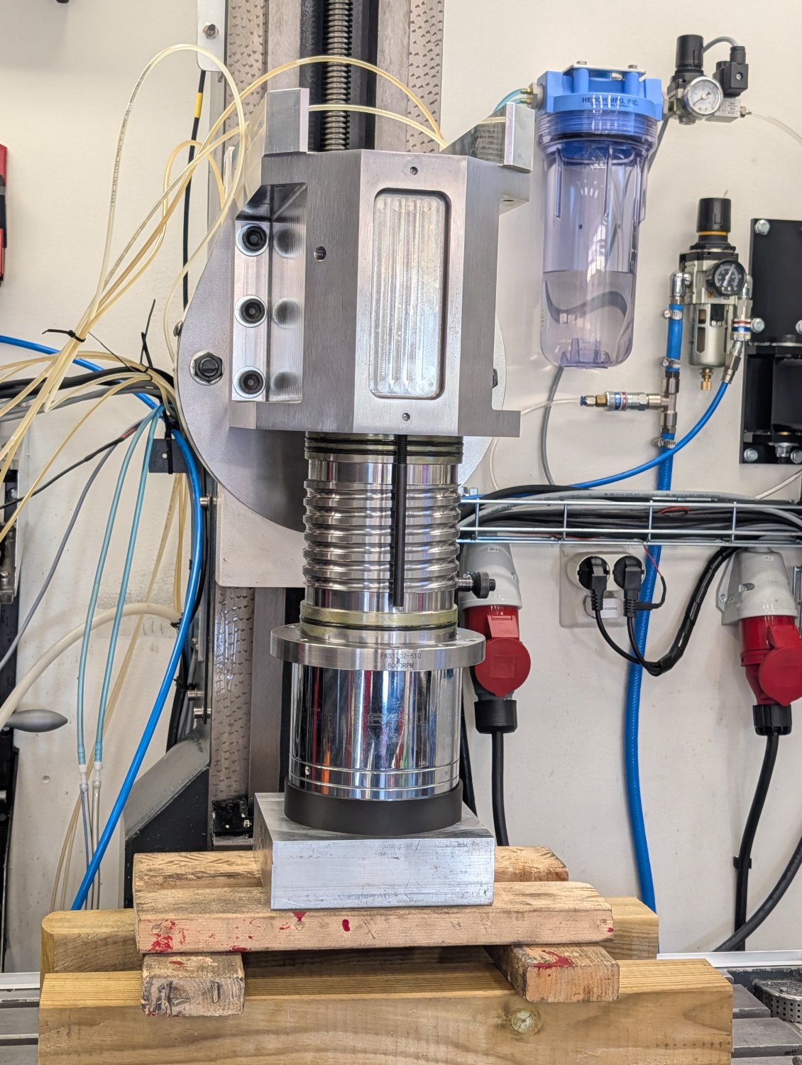
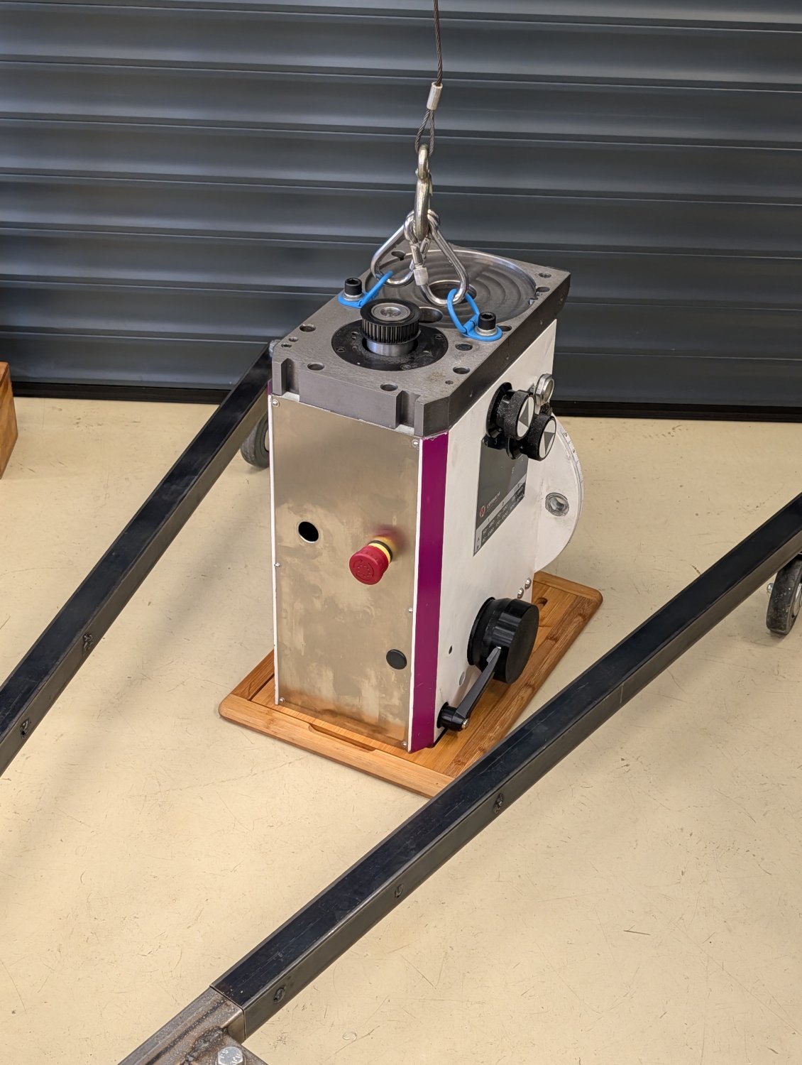
With the new spindle being rather heavy, fragile and quite expensive I 3D printed a small stand for it so that I could have it upright without putting any force on the bearings.


Installing the spindle was a bit nerve wrecking as the hole for it in the new head only has a clearance of one hundred of a millimeter.

So I took my time and slowly got it in place.


The following user(s) said Thank You: tommylight

Please Log in or Create an account to join the conversation.
More
1 month 2 weeks ago #349727 by Unlogic
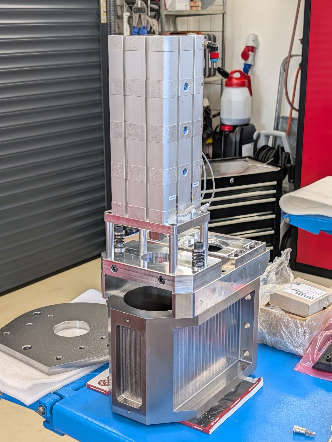
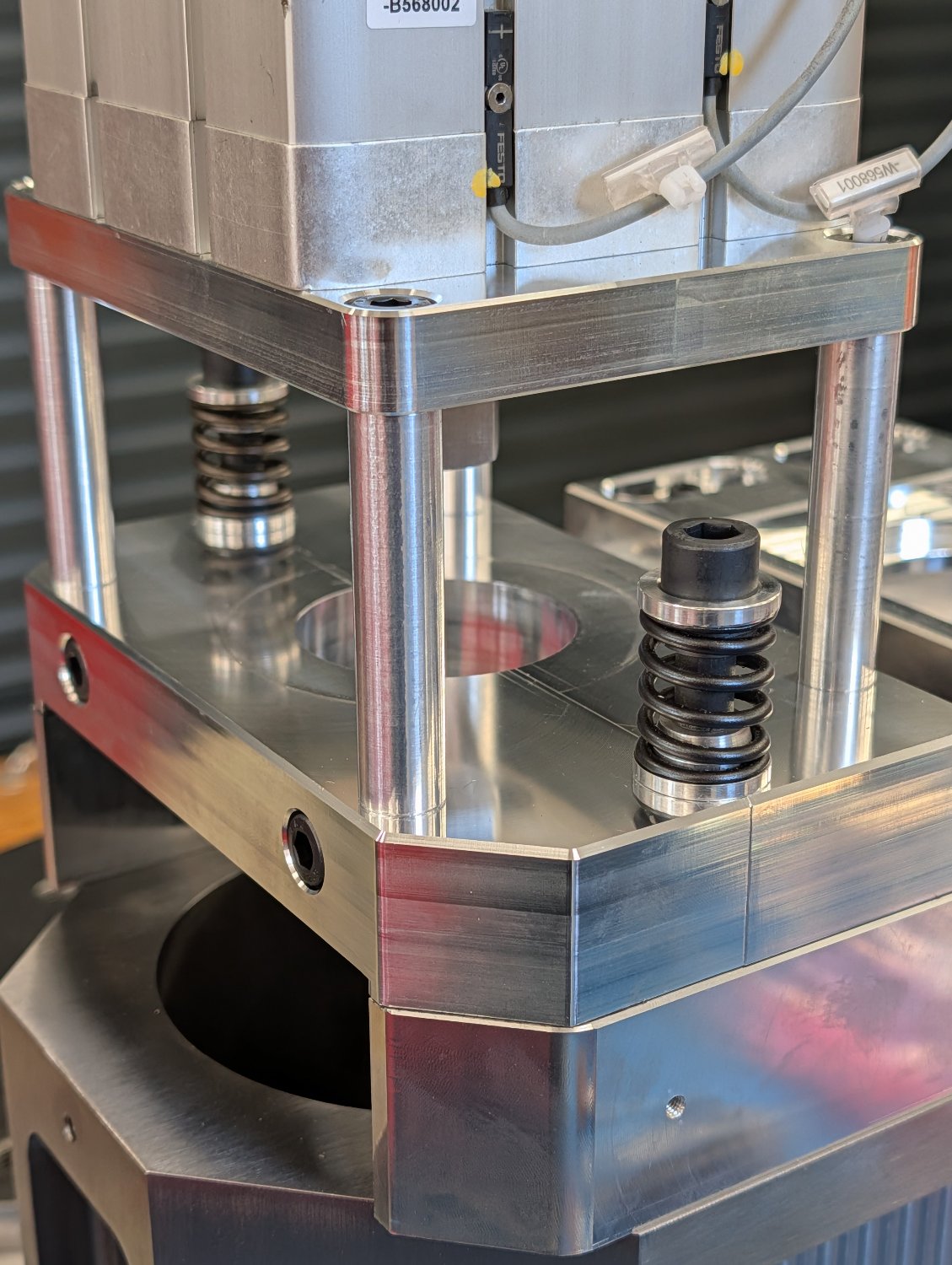
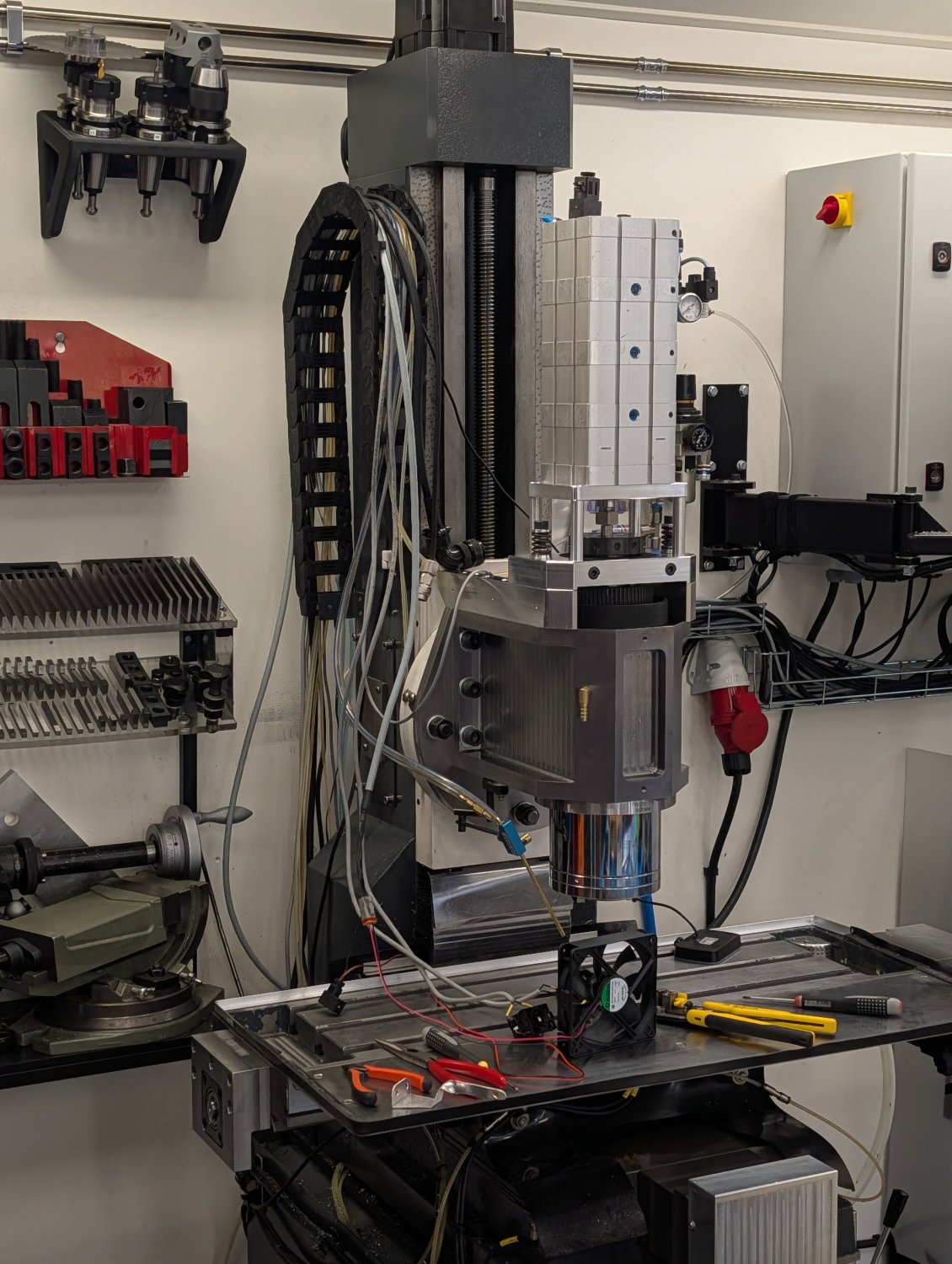
With the spindle installed I was keen on testing the pneumatic cylinder for the drawbar to make sure the whole assembly worked as planned.


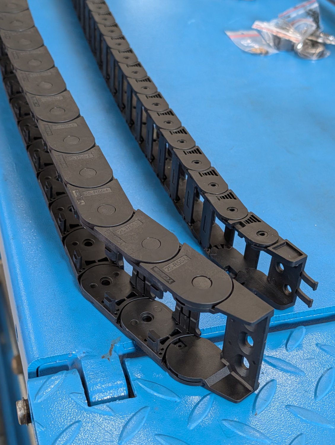
The next thing to tackle was the drag chain. The old one was completely full long ago and did not have space for the spindle cooling lines or the flood cooling line so I bought a larger one made from nylon which seems very sturdy.


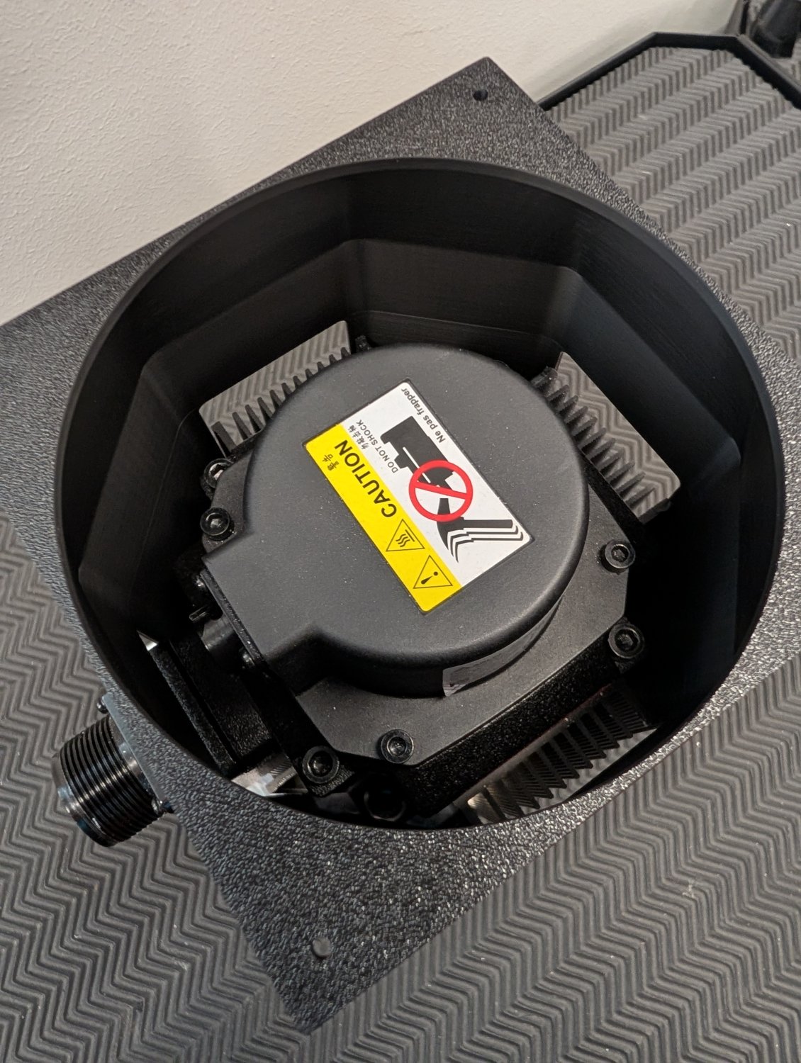
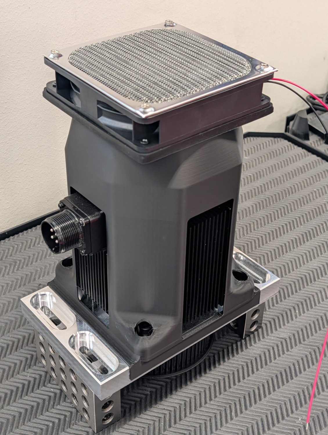
The Delta 2kw 6000 rpm servo I'm using for the spindle has been running at only for 3500 rpm previously due to my old spindle. Since it's going to be running at it's maximum rated speed of 6000 rpm now I decided to improve the cooling of it a bit to make sure it doesn't overheat.

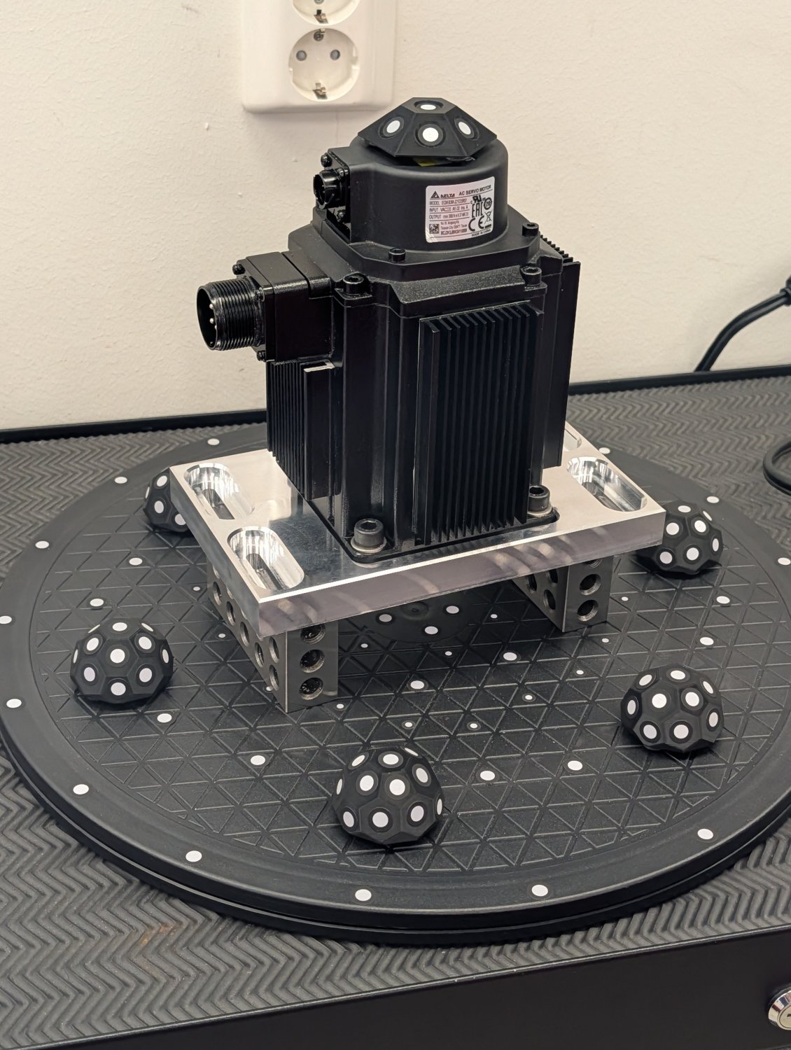
I started by 3D scanning the servo and it's mounting plate.


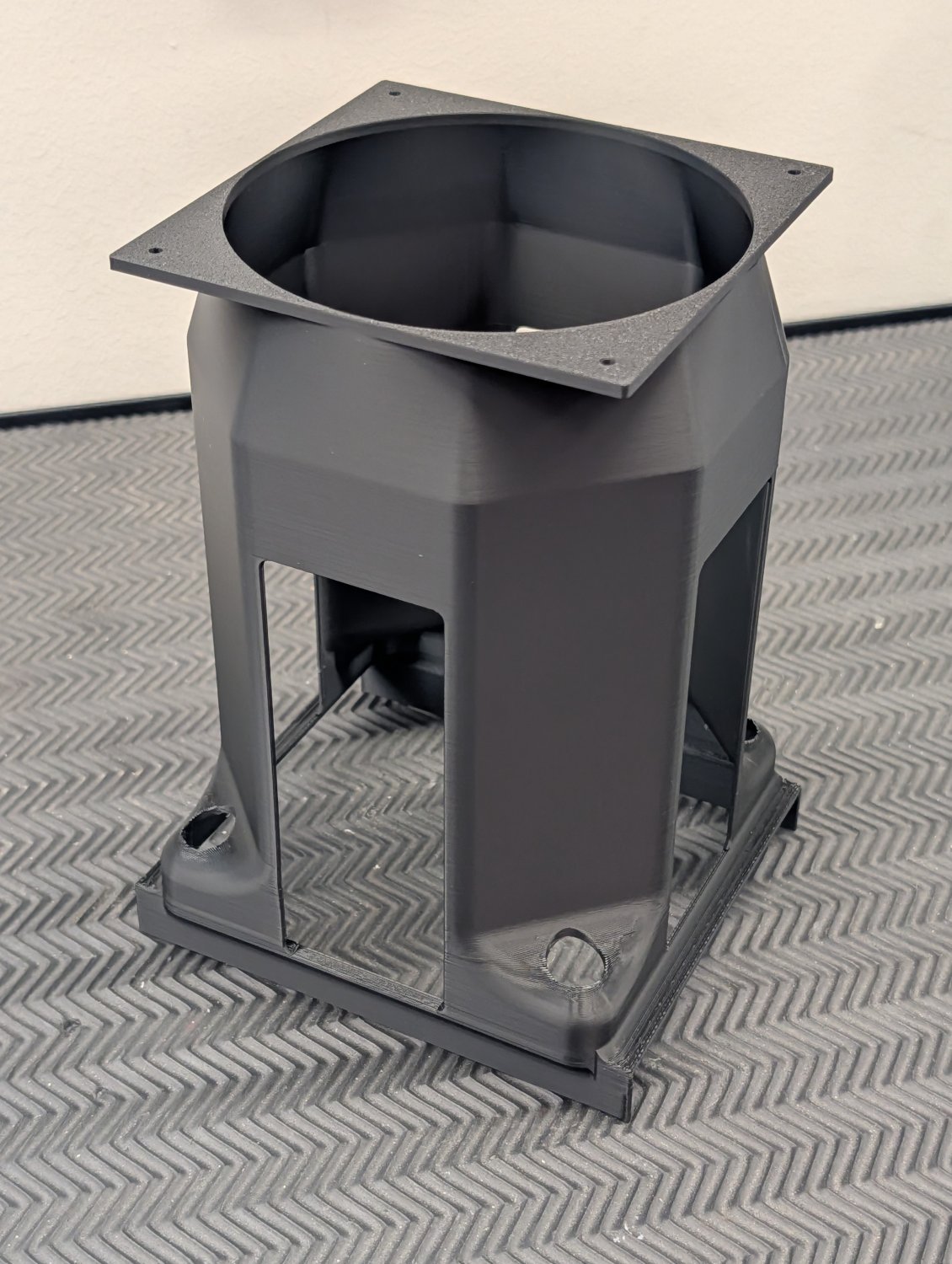
And around that model I designed the fan shroud.


The following user(s) said Thank You: tommylight

Please Log in or Create an account to join the conversation.
More
1 month 2 weeks ago - 1 month 2 weeks ago #349728 by Unlogic
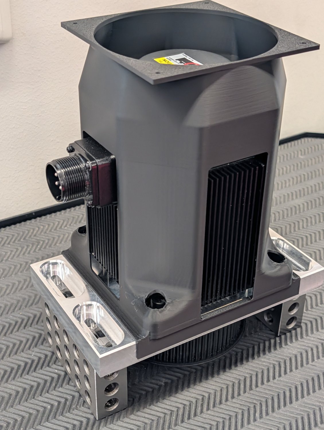
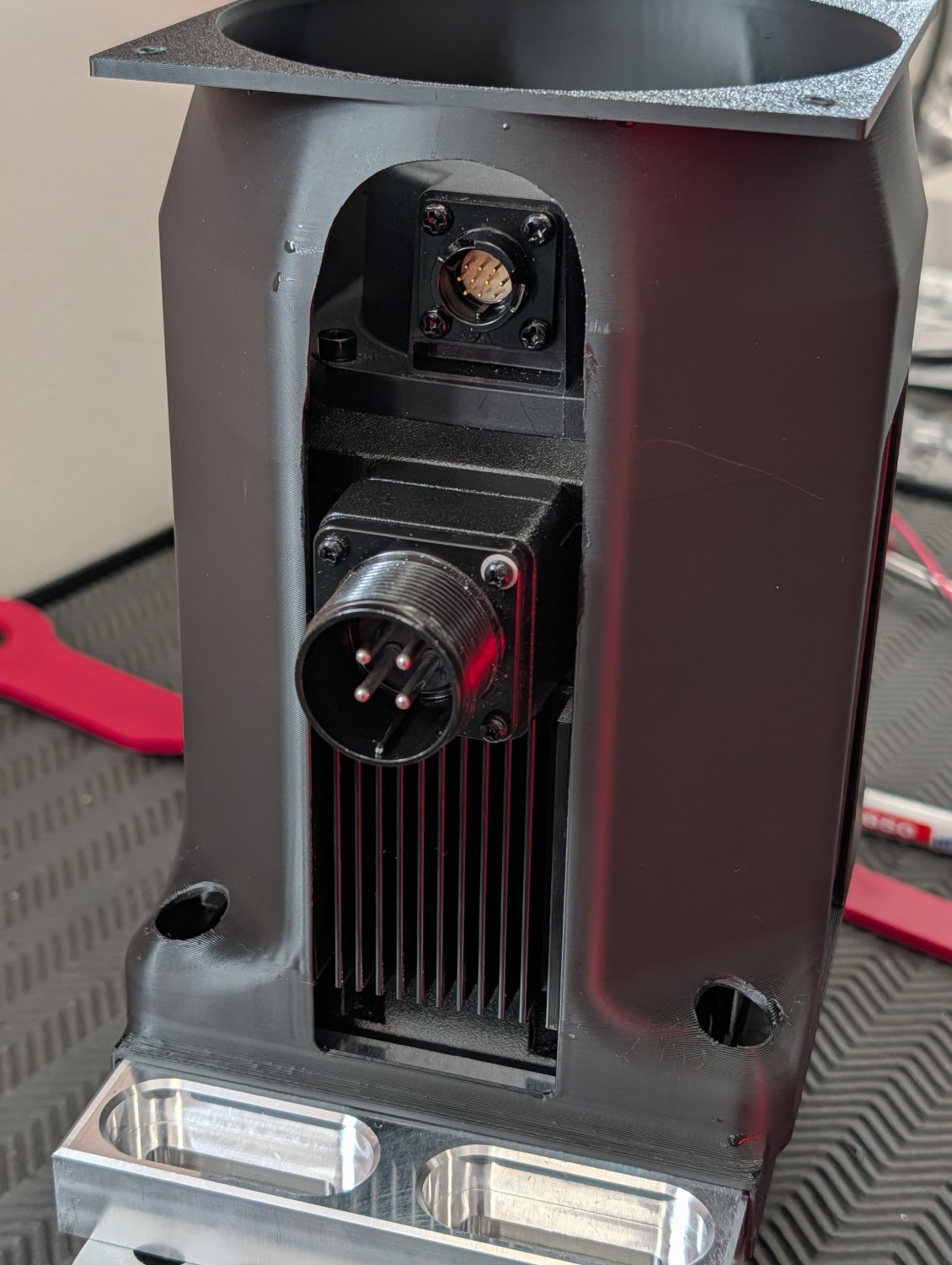
However when it was time to install the servo on the new head I realized that I had forgotten about the connector for the encoder so I had to open up the shroud a bit more on one side.


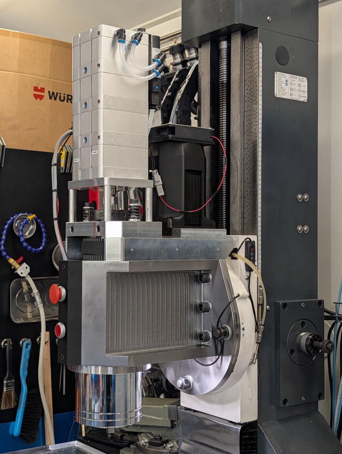
With that fixed I installed the servo on the machine.


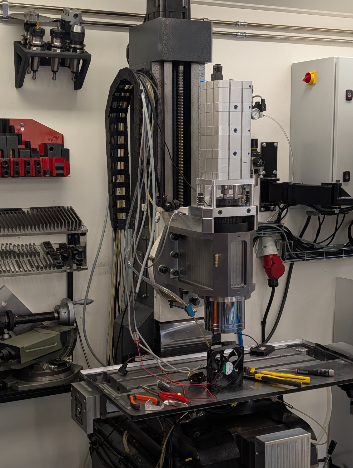
With the major components in place it was time for a first quick test


Next up is the liquid cooling for the spindle and then running in the new spindle bearings.
Last edit: 1 month 2 weeks ago by Unlogic.
The following user(s) said Thank You: tommylight, pommen, besriworld

Please Log in or Create an account to join the conversation.
Time to create page: 0.654 seconds
Powered by Kunena Forum