Optimum Optimill MH50V CNC conversion

More
1 year 1 month ago #335237 by Unlogic
The way covers I made recently greatly simplified the removal of chips from the table. So inspired by that success I decided to make a set of covers for the pockets at the ends of the table too.

I won't use these together with flood coolant but to make sure that any moisture that gets trapped under them still has a chance to escape I added some 2 mm holes.


The following user(s) said Thank You: tommylight

Please Log in or Create an account to join the conversation.

More
1 year 1 week ago - 1 year 1 week ago #336872 by Unlogic
The mill has continued to work great but as I started to mill larger parts and use the full 50 cm z-height of the machine my existing chip cover proved to be inadequate with chips ending up all over my garage.

I had already increased the size of the polycarbonate chip guard once before because of this reason so this time I decided to do "the final chip guard". In all honesty a full enclosure would probably be the way to go but I don't have space for that which is why I'm sticking to chip guards that sit on the table instead.

To get started I ordered a large sheet of 4 mm polycarbonate.


I then started a very analog process of designing the actual size and shape using the cardboard box that the polycarbonate sheet was delivered in.


Once I hade the decided size and shape I purchased some aluminum extrusions which I cut slightly too long and then milled to size in order to get square corners.


While at it I decided to add some more polycarbonate on each side of the column to protect everything behind the machine from chips. They attach with magnets so that they can be removed just by pulling them off.


Here is how it looks all assembled.


The door took a bit of thought to figure out what would be the best solution so that it wouldn't be in the way for operations which don't require it to be in place.

In the end I decided to go with this design so that it's very easy to remove. When removed I just set it down on the floor in front of the machine leaning against the stand.


Last edit: 1 year 1 week ago by Unlogic. Reason: Fixed typo
The following user(s) said Thank You: tommylight

Please Log in or Create an account to join the conversation.

More
9 months 2 days ago #342194 by Unlogic
There hasn't been any updates to this thread for a while. But the machine has worked great this autumn and I've created some nice billet aluminum car parts.


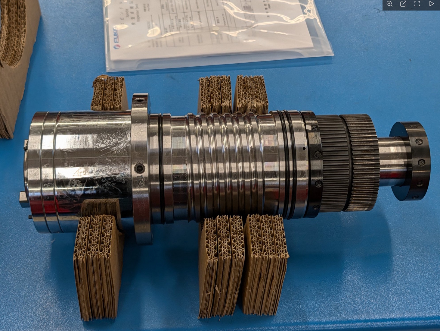
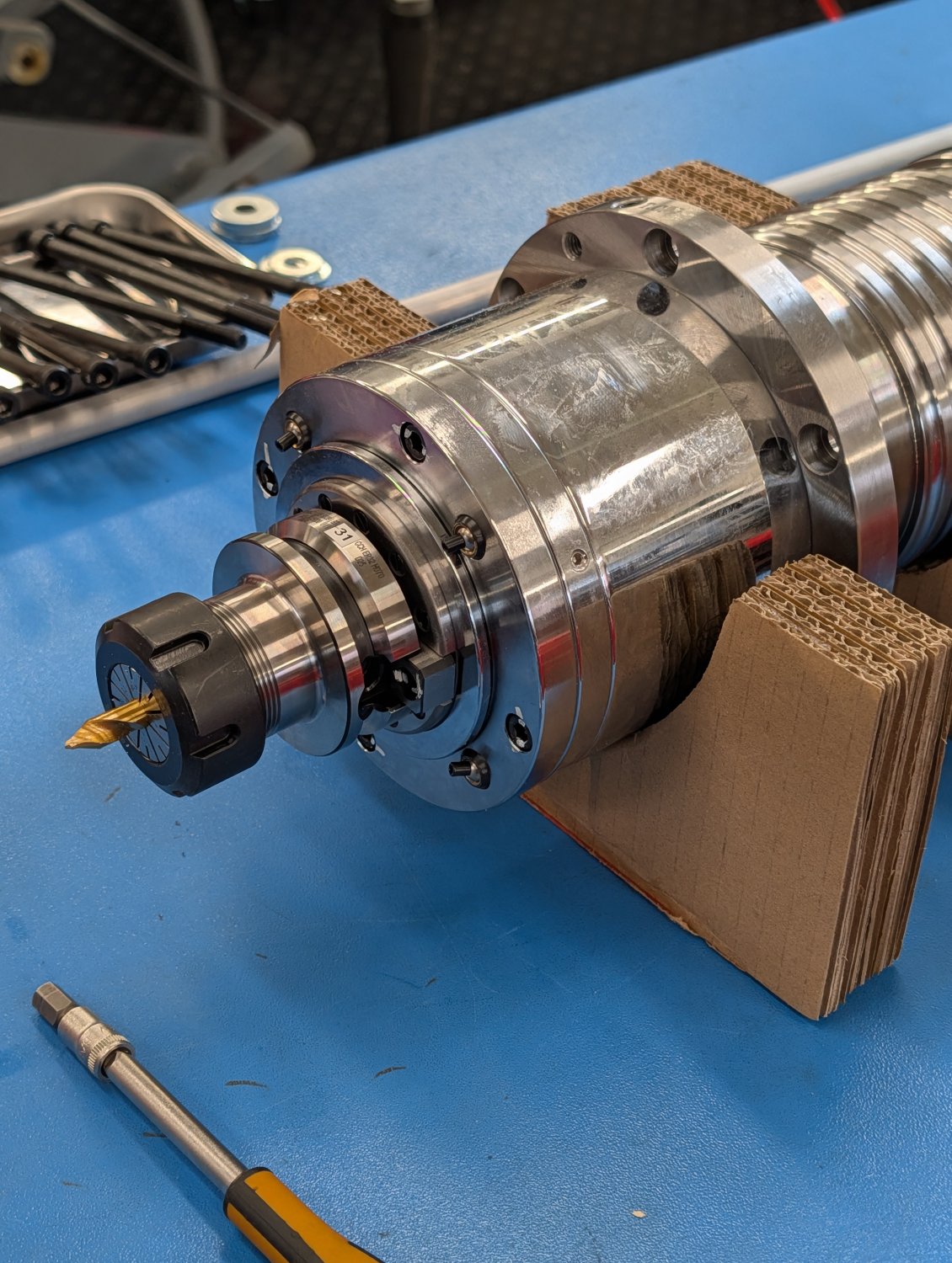
However it's finally timed for a much awaited spindle upgrade. I bought this 8000 rpm, liquid cooled BT40 spindle from FUKA/Swift. It seems like a very nice unit but it's gonna be a while before I can test it as I now need to design and manufacture a new head for the milling machine along with a much larger pneumatic tool release cylinder.


The following user(s) said Thank You: tommylight

Please Log in or Create an account to join the conversation.

More
1 month 2 weeks ago #349720 by Unlogic
After a longer than usual summer vacation break I've started another round of upgrades on the milling machine.

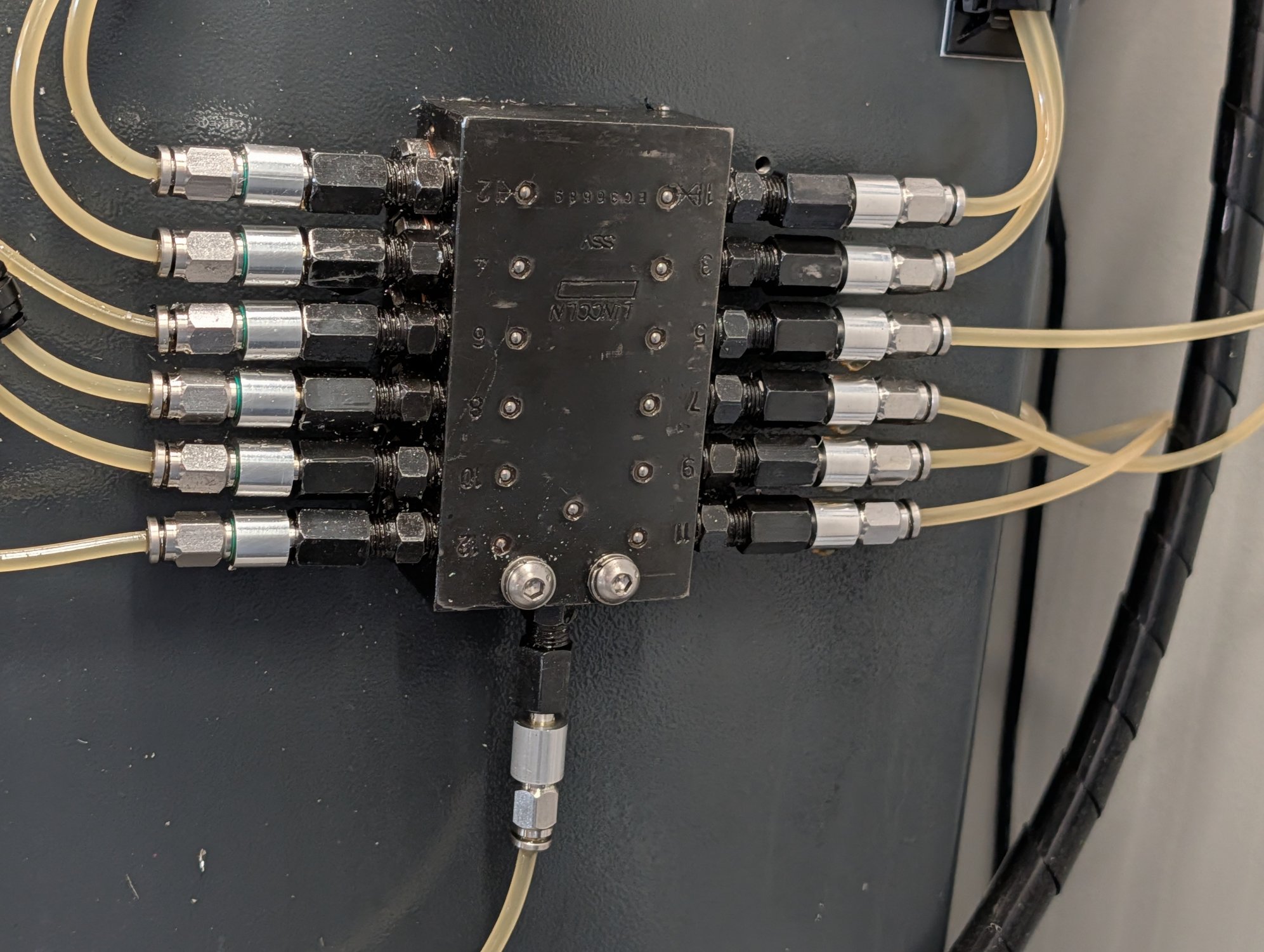
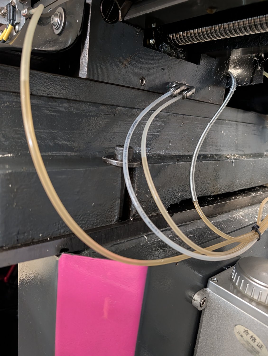
The first thing I did was to try and fix the leaks from my "Lincoln" clone progressive oil distribution block.


The tapered threads for the connections are not of the best quality and the built in check valves leak quite a bit.

This resulted in air in the lines if I didn't run the pump for the central lubrication for every week or so when the machine wasn't being used. It also left a pool of oil on the floor below the oil distribution block.


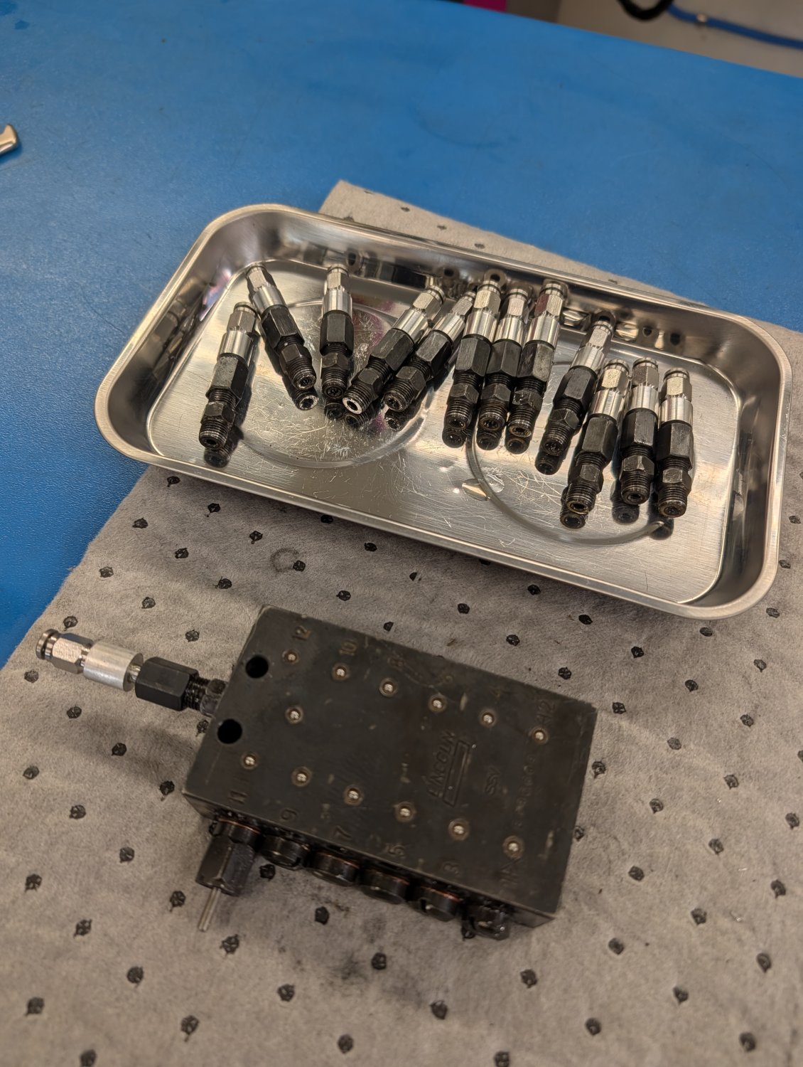
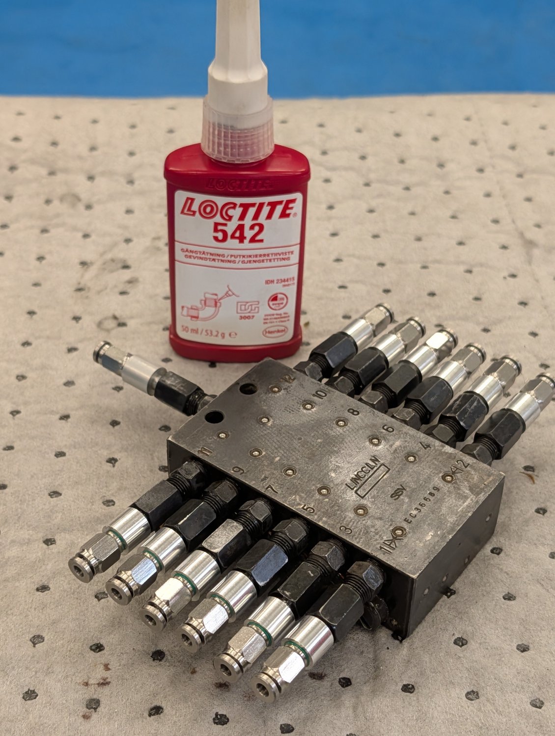
In order to try and fix this I removed all the connections from the block, cleaned the threads with brake cleaner and then reassembled it with Loctite thread sealant.


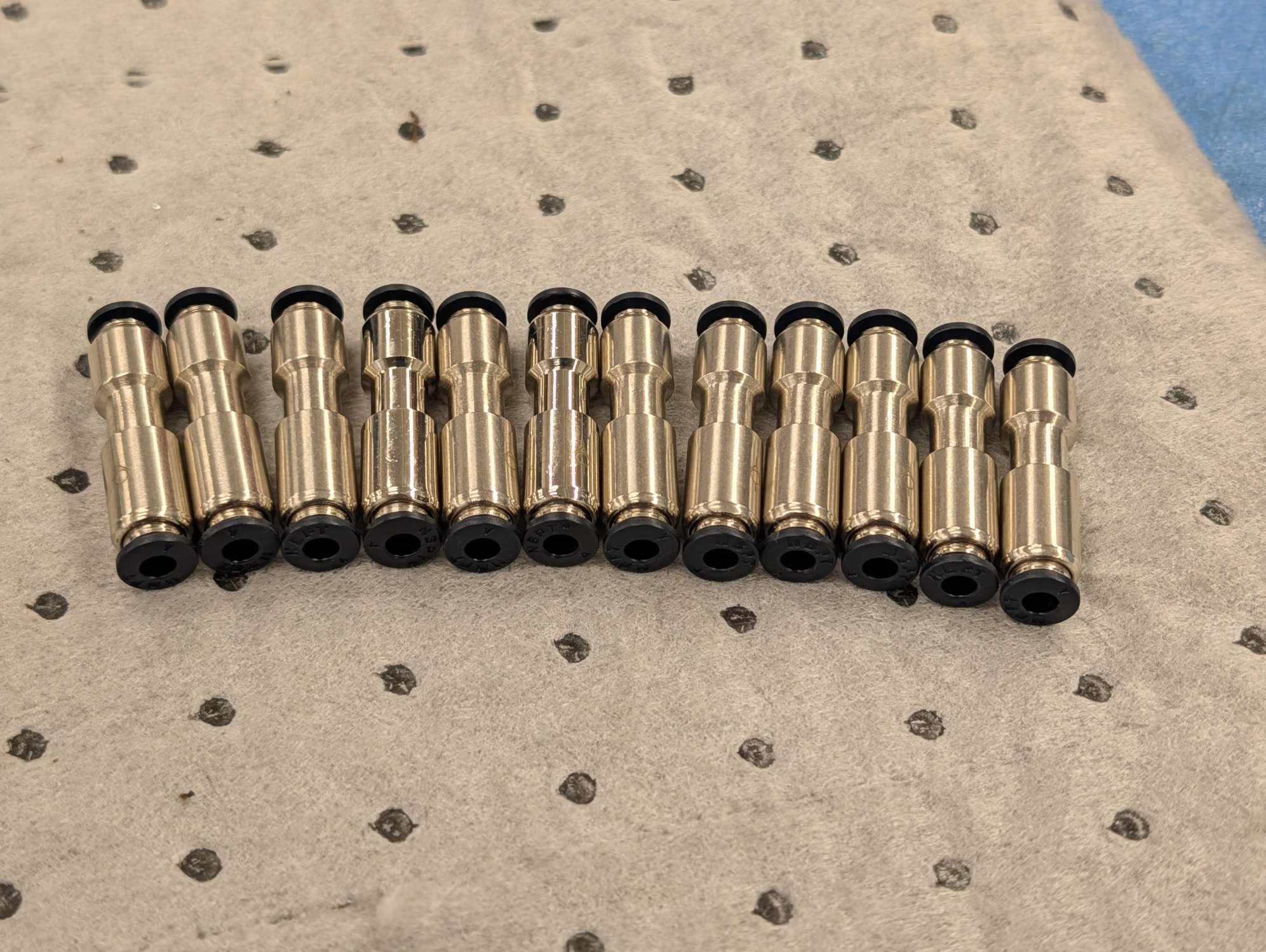
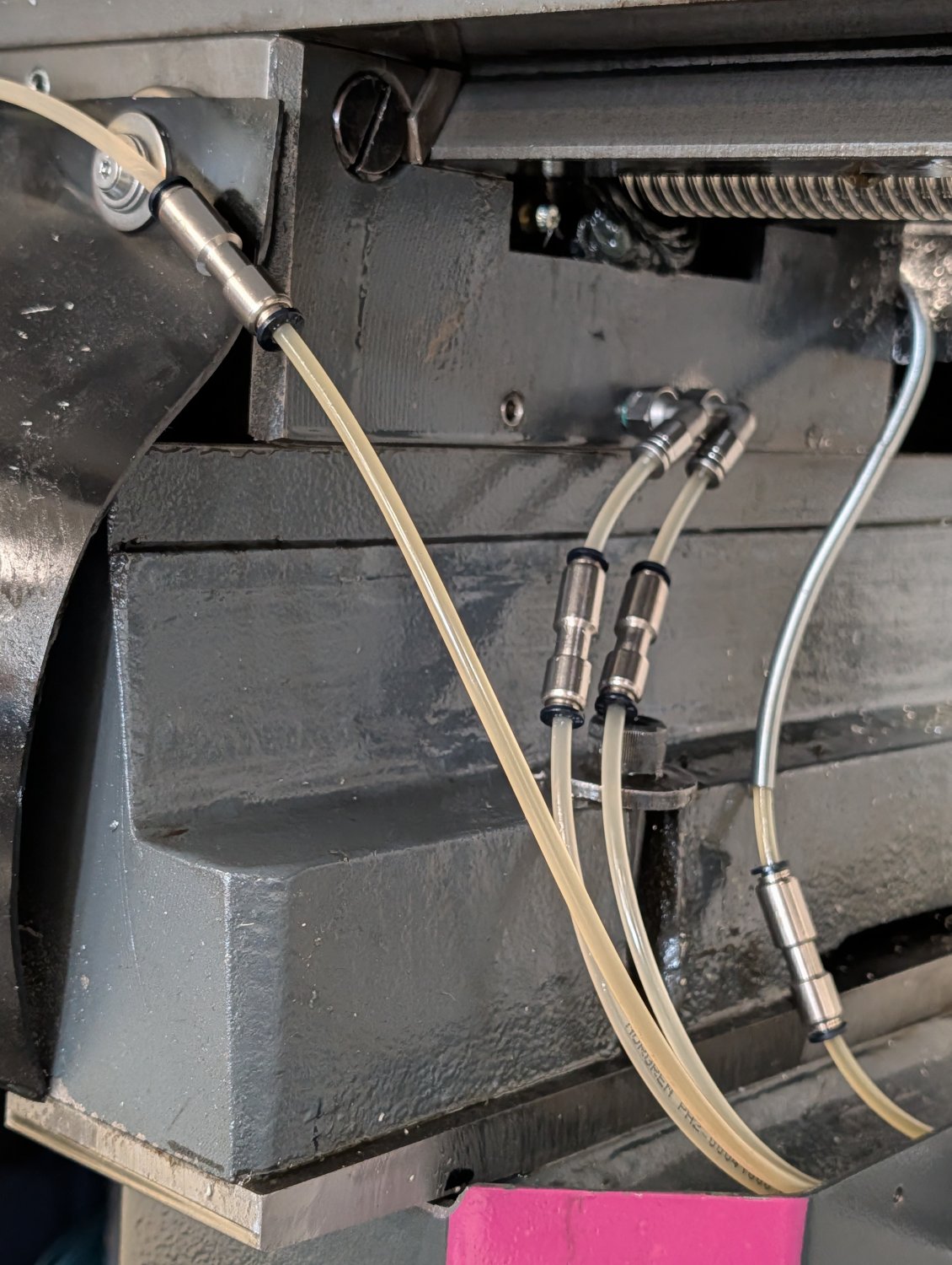
Then I added these small low pressure metal check valves I found on Aliexpress.


These changes seem to have significantly reduced the leakage from the oil distribution block and so far I have had no problems with air in the oil lines.

Please Log in or Create an account to join the conversation.

More
1 month 2 weeks ago - 1 month 2 weeks ago #349721 by Unlogic
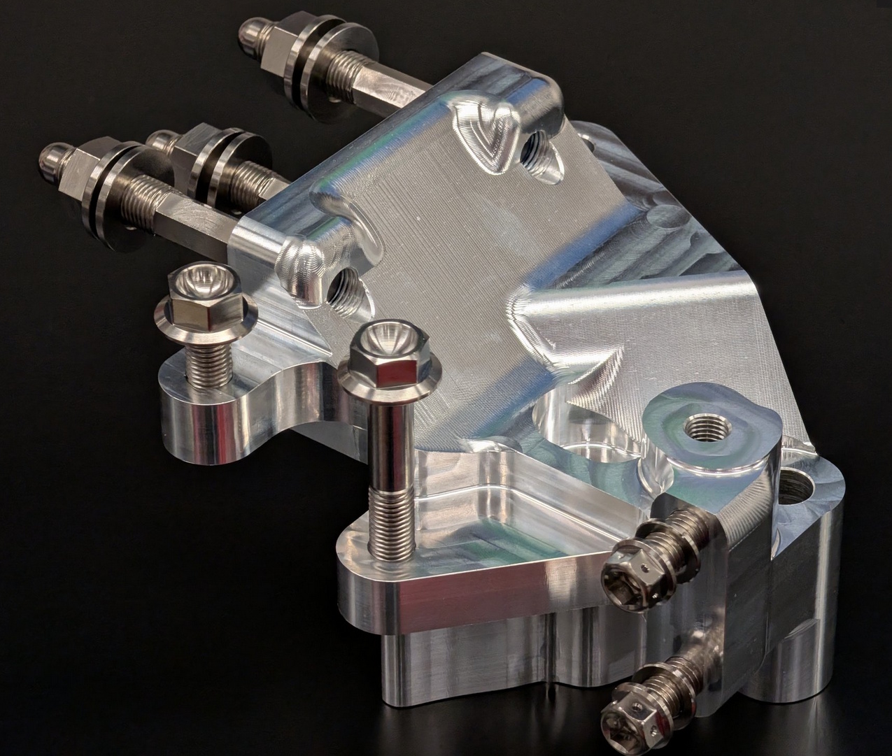
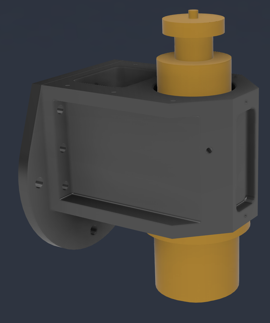
In order to fit the new spindle I'm gonna have to replace the whole head of the machine. So I designed a two piece design with an adapter plate that bolts on to the stock Z-axis.


The reason why I did it in two parts is to be able to reuse the head itself when I move on to a larger machine frame some time in the future.

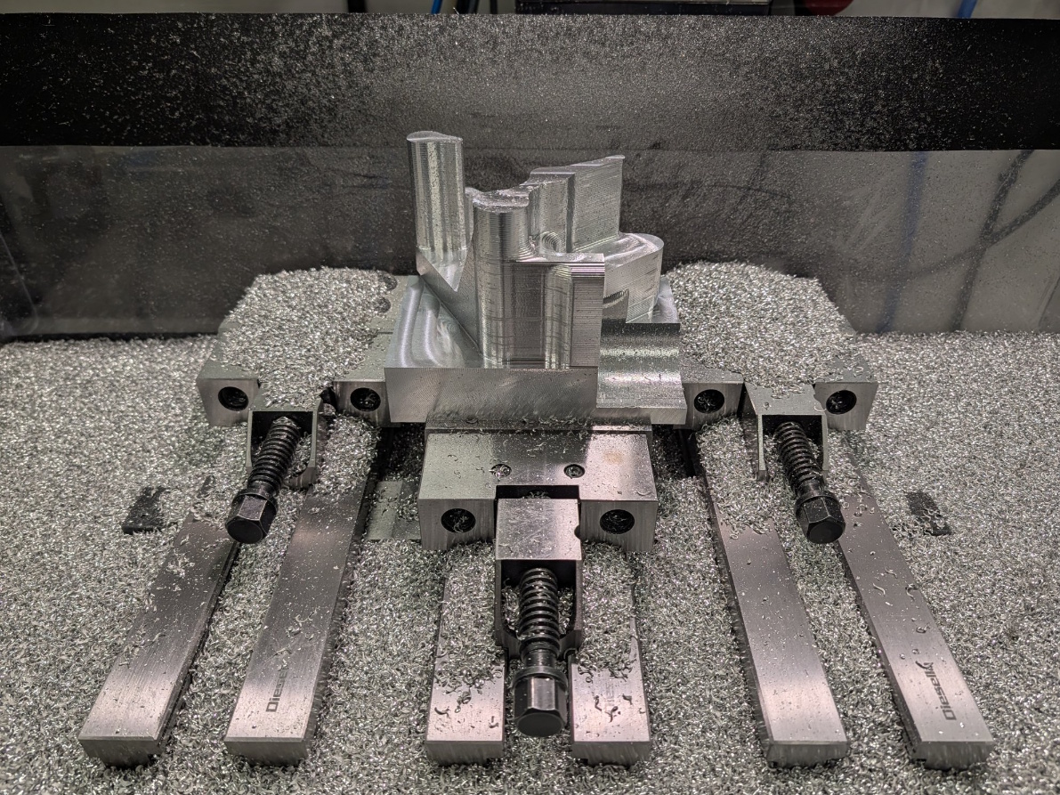
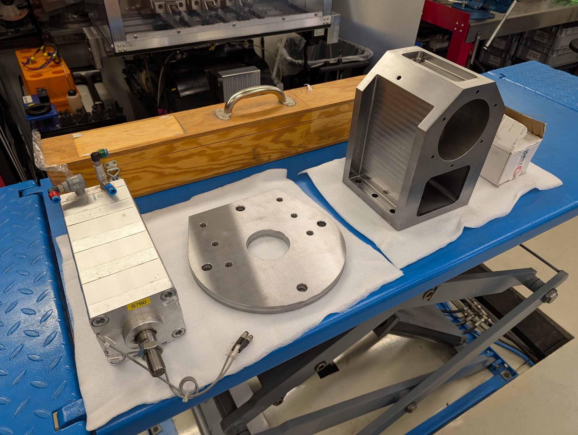
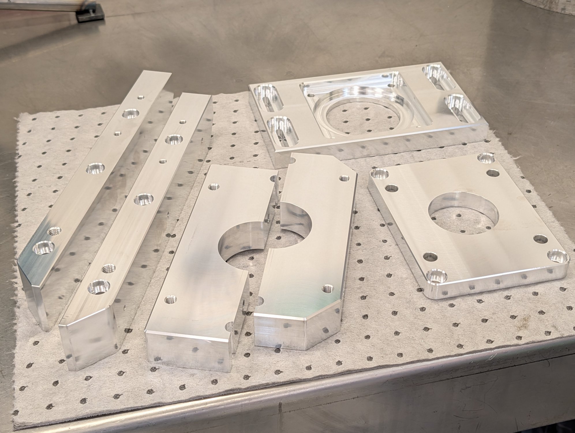
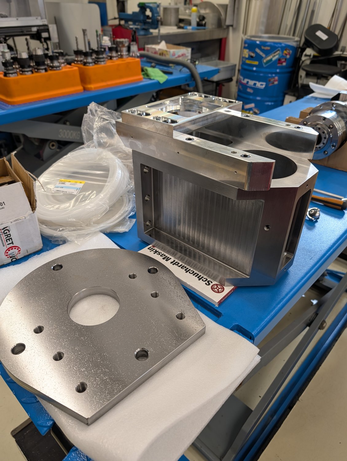
As the 120 mm hole in the head the for liquid cooled spindle needed to be made with very high precision I opted to have the parts made for me. This also enabled me to have the critical surfaces ground flat at the same time.

Here are the machined parts as they where delivered to me. Visible on the left side is also the pneumatic air cylinder I managed to find eBay.


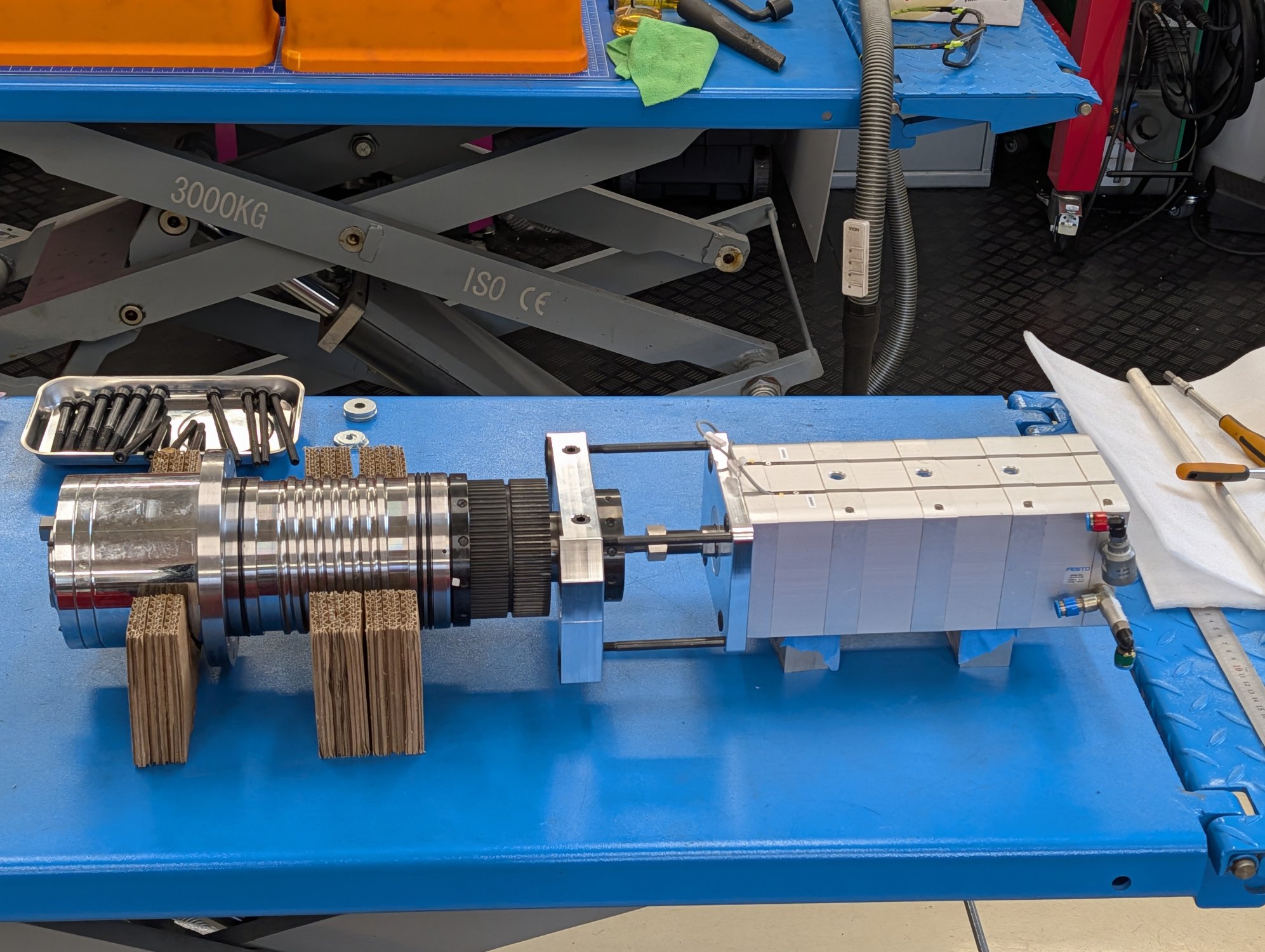
I try to avoid hydraulics as much as possible and so I was very happy to find a used stacked four stage 100 mm Festo pneumatic air cylinder for a very good price. It should provide enough force to release the drawbar in the new spindle at 8 bar of air pressure.

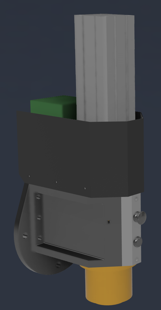
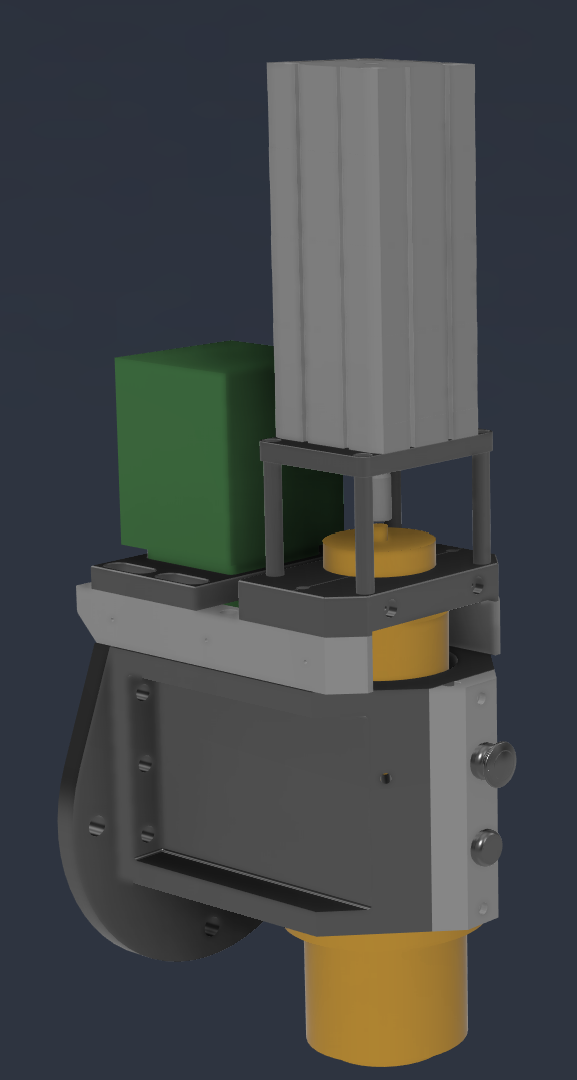
Here is how I have planned the milling head to looks with everything installed (with and without the top cover).


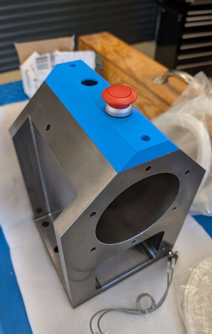
I 3D printed a test piece of the front button panel just to test the fitment and I think it came out okay.


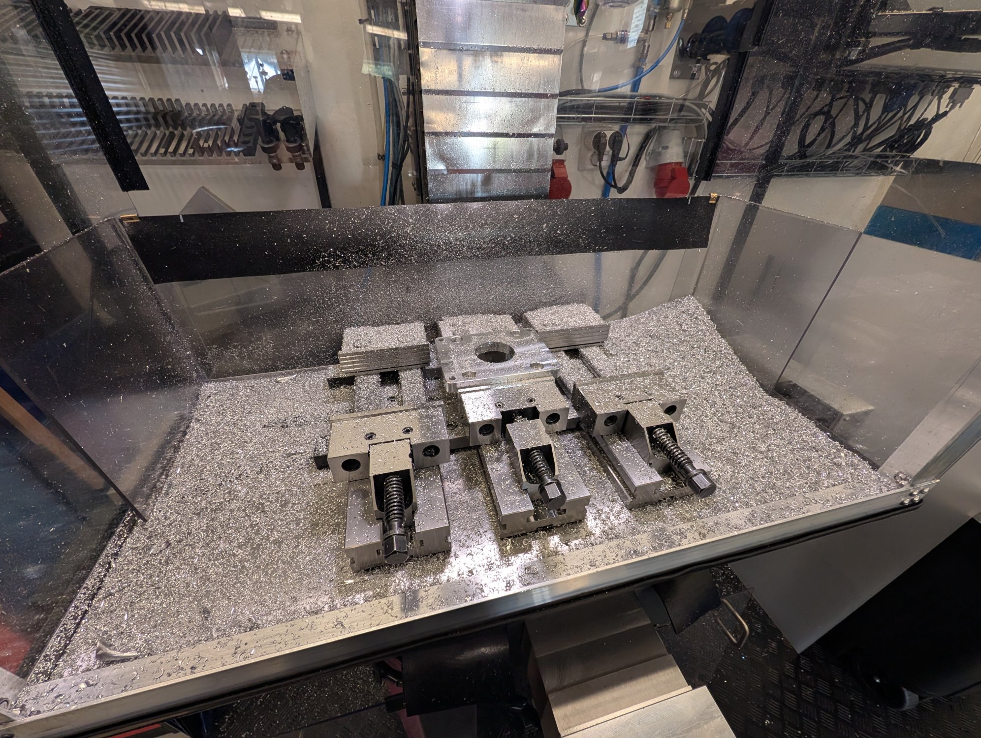
I've created 19 different CAM programs to make all the remaining parts from aluminum which kept me busy for a while.

In order to reduce the load on the spindle bearings I'm going attach the mount for the pneumatic air cylinder with springs so that the majority of the clamping force goes in the to the drawbar instead of the bearings. Hence the slightly more complicated setup compared to my old setup.

 
Last edit: 1 month 2 weeks ago by Unlogic.

Please Log in or Create an account to join the conversation.

More
1 month 2 weeks ago #349722 by Unlogic
I have milled all of the parts now so it's time to start the assembly.


Here is a quick test fitment of some of the parts that will go on the new head.


Here is a temporary setup to test if the stacked pneumatic cylinder was strong enough to release the drawbar.


The test was a success and confirmed that the pneumatic cylinder could release the drawbar without any issues at 8 bar of air pressure.


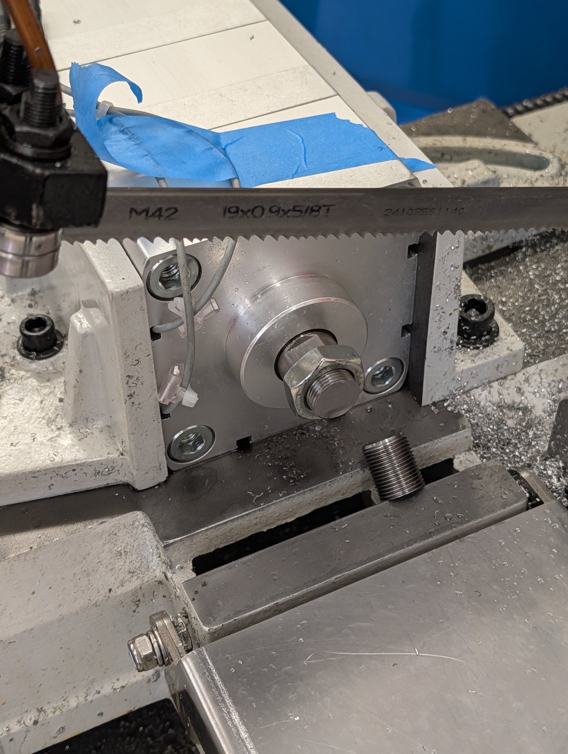
Once I had confirmed that the cylinder was working as intended I promptly put it in the bandsaw and shortened it a bit :)


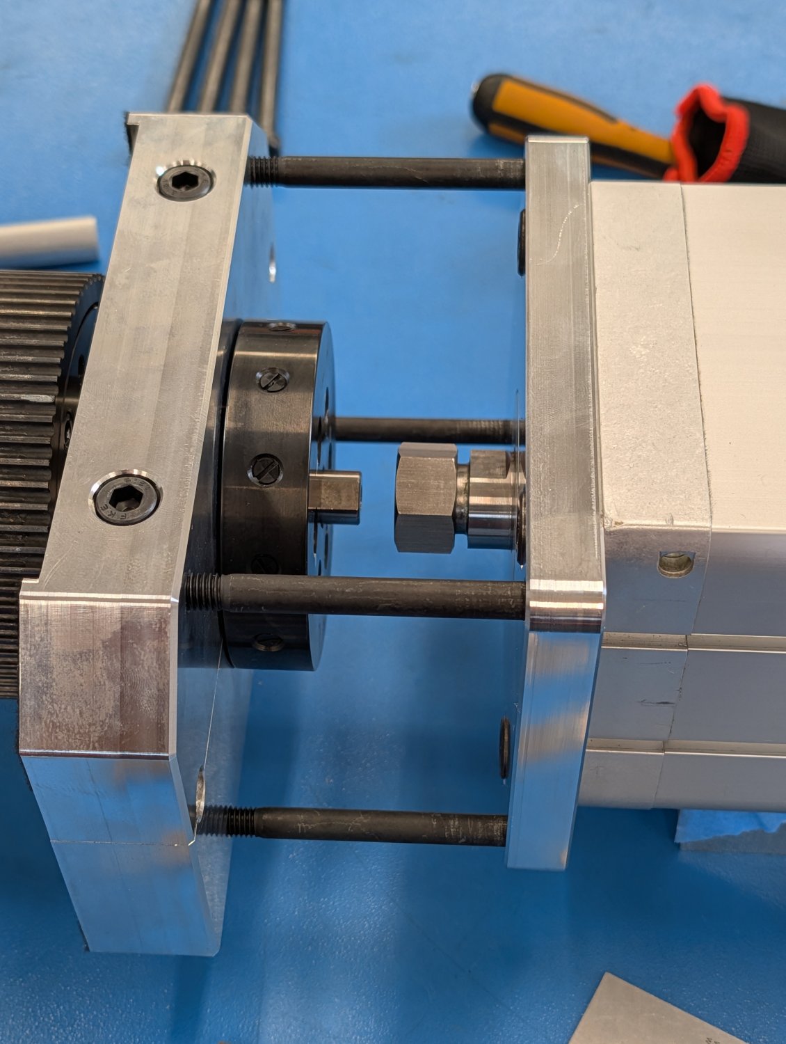
The next step is to make some aluminum sleeves for the four long bolts that hold the pneumatic cylinder to the lower fixture.

Please Log in or Create an account to join the conversation.

Time to create page: 0.144 seconds
Powered by Kunena Forum